EP0702222A1 - Detecteur de piqures - Google Patents
Detecteur de piqures Download PDFInfo
- Publication number
- EP0702222A1 EP0702222A1 EP95913381A EP95913381A EP0702222A1 EP 0702222 A1 EP0702222 A1 EP 0702222A1 EP 95913381 A EP95913381 A EP 95913381A EP 95913381 A EP95913381 A EP 95913381A EP 0702222 A1 EP0702222 A1 EP 0702222A1
- Authority
- EP
- European Patent Office
- Prior art keywords
- gas
- pallet
- signal
- difference
- digital signal
- Prior art date
- Legal status (The legal status is an assumption and is not a legal conclusion. Google has not performed a legal analysis and makes no representation as to the accuracy of the status listed.)
- Granted
Links
Images


Classifications
-
- G—PHYSICS
- G01—MEASURING; TESTING
- G01M—TESTING STATIC OR DYNAMIC BALANCE OF MACHINES OR STRUCTURES; TESTING OF STRUCTURES OR APPARATUS, NOT OTHERWISE PROVIDED FOR
- G01M3/00—Investigating fluid-tightness of structures
- G01M3/02—Investigating fluid-tightness of structures by using fluid or vacuum
- G01M3/04—Investigating fluid-tightness of structures by using fluid or vacuum by detecting the presence of fluid at the leakage point
- G01M3/20—Investigating fluid-tightness of structures by using fluid or vacuum by detecting the presence of fluid at the leakage point using special tracer materials, e.g. dye, fluorescent material, radioactive material
- G01M3/22—Investigating fluid-tightness of structures by using fluid or vacuum by detecting the presence of fluid at the leakage point using special tracer materials, e.g. dye, fluorescent material, radioactive material for pipes, cables or tubes; for pipe joints or seals; for valves; for welds; for containers, e.g. radiators
- G01M3/226—Investigating fluid-tightness of structures by using fluid or vacuum by detecting the presence of fluid at the leakage point using special tracer materials, e.g. dye, fluorescent material, radioactive material for pipes, cables or tubes; for pipe joints or seals; for valves; for welds; for containers, e.g. radiators for containers, e.g. radiators
Definitions
- the present invention relates to a pinhole inspecting apparatus for inspecting a pinhole of a flexible closed container.
- a substance which is liable to change in color tone under oxygen or humid conditions, for example, is contained in closed condition in a packaging container, then it is judged on the basis of change in the color tone of the substance whether or not the pinhole or the like is present.
- a pinhole inspecting method in the case of a rigid container in which the container is filled with an inspecting gas under pressure and any leakage gas is inspected by a gas detector to find whether or not a pinhole is present. The gas detector converts any inspecting gas leakage into an electric signal corresponding to amount of the leakage per unit time.
- Japanese Patent Application Nos. 5-344297 and 5-339527 there is disclosed a method and an apparatus, developed by the present inventor, for inspecting a pinhole of a flexible container, such as plastic bag etc., by using a gas detector.
- a pinhole inspecting method any possible leakage of inert gas from an inert gas-filled, closed plastic bag is electrically checked.
- a threshold value corresponding to a change in electrical conditions caused by environmental change is preliminarily determined for each measurement, and it is judged by checking that the measured value has exceeded the threshold value or otherwise whether or not a gas leakage or a pinhole is present.
- An object of the present invention is to provide, with a view to eliminating such conventional problems, a pinhole inspecting apparatus which enables accurate and rapid inspection of pinhole of a closed container so as to satisfy recent requirements of strict quality, performance and rapidity.
- a pinhole inspecting apparatus comprises a pallet for dischargeably containing a closed container filled with a gas, the pallet having a suction hole, a gas leakage detecting unit adapted to be connected at an inspecting position to the suction hole for communication with the interior of the pallet, such that when a gas of the same kind as said gas is present in that interior, the gas leakage detecting unit generates an analog signal having a voltage corresponding to amount of the leakage of the gas per unit time, an A/D converter for converting the analog signal into a digital signal, and a first arithmetic unit for finding from the digital signal a slope of a regression line representing the relationship between a voltage corresponding to the magnitude of the signal and time, and calculating the difference between the value of the slope and a maximum slope value which has been preliminarily inputted with respect to a regression line for the same kind of gas in the air as said gas, the first arithmetic unit being further operative
- the pinhole inspecting apparatus comprises a pallet for dischargeably containing a closed container filled with a gas, the pallet having a suction hole, a gas leakage detecting unit adapted to be connected at an inspecting position to the suction hole for communication with the interior of the pallet, such that when a gas of the same kind as said gas is present in that interior, the gas leakage detecting unit generates an analog signal having a voltage corresponding to amount of the leakage of the gas per unit time, an A/D converter for converting the analog signal into a digital signal, and a second arithmetic unit for calculating the difference between said digital signal and a previous digital signal at a point of time traced back a predetermined time from the time of detection of the data on the basis of which said digital signal is outputted, the second arithmetic unit being further operative to output an abnormality signal when it is determined that there is a difference falling out of an allowable range between said difference and, for the same kind of gas present in the air as said
- the pinhole inspecting apparatus comprises a pallet for dischargeably containing a closed container filled with a gas, the pallet having a suction hole, a gas leakage detecting unit adapted to be connected at an inspecting position to the suction hole for communication with the interior of the pallet, such that when a gas of the same kind as said gas is present in that interior, the gas leakage detecting unit generates an analog signal having a voltage corresponding to amount of the leakage of the gas per unit time, an A/D converter for converting the analog signal into a digital signal, a first arithmetic unit for finding from the digital signal a slope of a regression line representing the relationship between a voltage corresponding to the magnitude of the signal and time, and calculating the difference between the value of the slope and a maximum slope value which has been preliminarily inputted with respect to a regression line for the same kind of gas in the air as said gas, the first arithmetic unit being further operative to output an abnormality signal when the difference falls out
- helium gas is employed as the gas.
- the present invention it is possible to inspect a pinhole of closed container under conditions free from any environmental influence. Namely, the present invention permits accurate and reliable inspection of pinhole of closed container without being influenced by any environmental change, for example, presence or non-presence in the air of the same kind of gas as the gas sealed in the closed container.
- Fig. 1 illustrates a pinhole inspecting apparatus according to a first or a fourth embodiment of the present invention.
- the apparatus comprises a pallet 1, a gas leakage detecting unit 2, an A/D converter 3, a first arithmetic unit 4, and a removing unit 5.
- the pallet 1 has a chamber 12 for dischargeably containing therein one or plural closed containers 11, three in this embodiment, which are subject to pinhole inspection. Meanwhile, in Fig. 1, a suction hole 13 is formed on an upper face of each of the chambers 12 of the pallet 1.
- the pallet 1 is carried to an inspecting position as shown, by a conveyor 14 which is movable intermittently at a constant pitch.
- the closed container 11 to be inspected is used to contain solid or liquid matter, for example, tablet or powder drug, and there is no limitation with respect to its material and configuration.
- the container 11 may be, for example, various types of plastic bags, or molded products, and various types of metallic containers.
- gas is contained in each of the closed container 11.
- the gas may be helium gas, flon gas, nitrogen gas, carbon dioxide gas, or neon gas, of which helium gas is most preferred.
- the gas leakage detecting unit 2 includes a gas detecting means 15 and an introducing pipe 17 provided with an electromagnetic on-off valve 16.
- the introducing pipe 17 engages with the suction hole 13 of the chamber 12 of the pallet 1, when the suction hole 13 reaches the inspecting position, so as to conduct leakage gas to the gas detecting means 15.
- the gas detecting means 15 per se is known, in which, for example, helium gas sucked together with air is ionized and passed through a magnetic field so that helium ions only are collected. At a site collecting the helium ions, a current proportional to amount of the helium gas leakage flows. At a resistor portion, the current is converted into voltage so that an analog signal showing the voltage is outputted.
- an expansion and contraction means for example, air cylinder, is disposed above a chamber 12 having a suction hole 13 coming to the inspecting position.
- an expansion and contraction means for example, air cylinder
- the chamber 12 and the closed container 11 are pressed from above so that gas leakage may be facilitated in the event of a pinhole being present on the closed container 11.
- the chamber 12 is brought under negative pressure so that gas leakage can be facilitated if a pinhole exists.
- the analog signal is converted into a digital signal.
- a maximum value of slope of a regression line for the same kind of a gas in air as the above-mentioned gas is preliminarily inputted to the first arithmetic unit 4. Then, it is judged at the first arithmetic unit 4 whether or not the difference between the value of slope b and the maximum value is within an allowable range, and if the difference falls out of the allowable range, an abnormality signal is outputted from the first arithmetic unit 4. In other words, in the case that a pinhole is present on a closed container 11 inspected, the abnormality signal is outputted.
- the removing unit 5 includes a control panel 21 and a pusher means 22, for example, an air cylinder. Upon receipt of an abnormality signal from the first arithmetic unit 4 by the control panel 21, the control panel 21 outputs a signal to activate the pusher means 22 such that the corresponding pallet 1 containing the abnormal container 11 is pushed out of the line.
- helium gas is employed as the gas. It is understood, however, that the first embodiment is not limited to this arrangement.
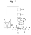
- Fig. 2 illustrates a pinhole inspecting apparatus according to a second or a fourth embodiment of the present invention, which is substantially identical with the apparatus shown in Fig. 1 except that a second arithmetic unit 6 is incorporated in place of the first arithmetic unit 4. Therefore, parts corresponding to those shown in Fig. 1 are designated by like reference numerals and description thereof is omitted.
- the second arithmetic unit 6 receives a digital signal from the A/D converter 3 so as to calculate a difference between this digital signal and a previous digital signal.
- Data for producing the previous digital signal is detected at a time point preceding by a predetermined period a time point of detection of data for producing the digital data.
- the second arithmetic unit 6 Whilst, in the second arithmetic unit 6, a maximum value is preliminarily inputted for the same kind of gas present in the air as above-mentioned gas, with respect to differences between similar digital signals at the same time interval as the above-mentioned predetermined time. Then, at the second arithmetic unit 6, it is judged whether or not the difference between the difference based on the data on the gas in the pallet 1 and above-mentioned maximum difference is within an allowable range, and if the difference falls out of the allowable range, the second arithmetic unit 6 outputs an abnormality signal.
- the difference between digital signals at two points of time is compared with above-mentioned maximum value, and the difference therebetween is taken as a basis for judgement.
- helium gas is employed as the gas. It is understood, however, that the second embodiment is not limited to this arrangement.
- Fig. 3 illustrates a pinhole inspecting apparatus according to a third or a fourth embodiment of the present invention, which is substantially identical with the apparatus shown in Fig. 1 except that the apparatus shown in Fig. 3 includes a second arithmetic unit 6 in addition to the first arithmetic unit 4. Therefore, parts corresponding to those shown in Fig. 1 are designated by like reference numerals and description thereof is omitted.
- an abnormality signal is outputted in the apparatus shown in Fig. 1 and an abnormality signal is outputted in the apparatus shown in Fig. 2 and an abnormality signal is outputted in the apparatus shown in Fig. 2, an abnormality signal is outputted and a pallet corresponding to the abnormality signal is removed from the line.
- helium gas is employed as the gas. It is understood, however, that the third embodiment is not limited to this arrangement.
Landscapes
- Physics & Mathematics (AREA)
- General Physics & Mathematics (AREA)
- Examining Or Testing Airtightness (AREA)
- Glass Compositions (AREA)
- Fire-Detection Mechanisms (AREA)
- Electrical Discharge Machining, Electrochemical Machining, And Combined Machining (AREA)
- Absorbent Articles And Supports Therefor (AREA)
Applications Claiming Priority (4)
| Application Number | Priority Date | Filing Date | Title |
|---|---|---|---|
| JP6592694 | 1994-04-04 | ||
| JP06065926A JP3105390B2 (ja) | 1994-04-04 | 1994-04-04 | ピンホール検査装置 |
| JP65926/94 | 1994-04-04 | ||
| PCT/JP1995/000603 WO1995027193A1 (fr) | 1994-04-04 | 1995-03-30 | Detecteur de piqures |
Publications (3)
| Publication Number | Publication Date |
|---|---|
| EP0702222A1 true EP0702222A1 (fr) | 1996-03-20 |
| EP0702222A4 EP0702222A4 (fr) | 1998-09-16 |
| EP0702222B1 EP0702222B1 (fr) | 2001-11-14 |
Family
ID=13301071
Family Applications (1)
| Application Number | Title | Priority Date | Filing Date |
|---|---|---|---|
| EP95913381A Expired - Lifetime EP0702222B1 (fr) | 1994-04-04 | 1995-03-30 | Detecteur de piqures |
Country Status (9)
| Country | Link |
|---|---|
| US (1) | US5633454A (fr) |
| EP (1) | EP0702222B1 (fr) |
| JP (1) | JP3105390B2 (fr) |
| AT (1) | ATE208893T1 (fr) |
| AU (1) | AU688483B2 (fr) |
| CA (1) | CA2163085A1 (fr) |
| DE (1) | DE69523847T2 (fr) |
| ES (1) | ES2167422T3 (fr) |
| WO (1) | WO1995027193A1 (fr) |
Cited By (1)
| Publication number | Priority date | Publication date | Assignee | Title |
|---|---|---|---|---|
| WO1997039322A1 (fr) * | 1996-04-15 | 1997-10-23 | Espoon Paineilma Oy | Procede de traitement d'un produit et installation de detection de fuites |
Families Citing this family (8)
| Publication number | Priority date | Publication date | Assignee | Title |
|---|---|---|---|---|
| US6351984B1 (en) * | 2000-02-23 | 2002-03-05 | Aradigm Corporation | Inspection method and device for non-destructive analysis of a container material |
| US6763702B2 (en) * | 2002-12-19 | 2004-07-20 | Agilent Technologies, Inc. | Method and apparatus for hermeticity determination and leak detection in semiconductor packaging |
| DE102004050762A1 (de) * | 2004-10-16 | 2006-04-20 | Inficon Gmbh | Verfahren zur Lecksuche |
| US7557482B2 (en) * | 2006-07-31 | 2009-07-07 | Caterpillar Inc. | Axial-flux electric machine |
| US20080024035A1 (en) * | 2006-07-31 | 2008-01-31 | Caterpillar Inc. | Power system |
| US8823294B2 (en) * | 2007-06-27 | 2014-09-02 | Brooks Automation, Inc. | Commutation of an electromagnetic propulsion and guidance system |
| WO2012125108A1 (fr) * | 2011-03-16 | 2012-09-20 | Norden Machinery Ab | Procédé et ensemble de détection de fuite |
| US8582105B1 (en) * | 2012-06-14 | 2013-11-12 | Intermolecular, Inc. | Method and apparatus for leak detection in H2Se furnace |
Family Cites Families (11)
| Publication number | Priority date | Publication date | Assignee | Title |
|---|---|---|---|---|
| US3591944A (en) * | 1969-03-03 | 1971-07-13 | Safeway Stores | Method and apparatus for detection of leaks in seals of packages |
| US3744210A (en) * | 1971-06-28 | 1973-07-10 | Standard Packaging Corp | Packaging machine and method |
| JPS53113351A (en) * | 1977-03-15 | 1978-10-03 | Toshiba Corp | Auomatic leak inspecting device |
| JPS5459191A (en) * | 1977-10-19 | 1979-05-12 | Toshiba Corp | Method and apparatus for detection of minute leakage |
| JPS58158533A (ja) * | 1982-03-16 | 1983-09-20 | Toshiba Corp | リ−クテスト方法 |
| JPS5983118A (ja) * | 1982-11-05 | 1984-05-14 | Kokusai Denshin Denwa Co Ltd <Kdd> | 光海底中継器用ジヨイントチヤンバ |
| JPH0737912B2 (ja) * | 1987-09-22 | 1995-04-26 | 食品産業オンラインセンサー技術研究組合 | 窒素ガス充填包装体におけるリークの検査方法 |
| JPH01270632A (ja) * | 1988-04-22 | 1989-10-27 | Mitsubishi Electric Corp | 漏洩検知装置 |
| US4905505A (en) * | 1989-03-03 | 1990-03-06 | Atlantic Richfield Company | Method and system for determining vapor pressure of liquid compositions |
| US5029463A (en) * | 1990-03-01 | 1991-07-09 | American Air Liquide | Leak detection device for in-line measurement of package integrity |
| US7697634B2 (en) | 2006-08-25 | 2010-04-13 | Tektronix, Inc. | Interpolation of complex signals |
-
1994
- 1994-04-04 JP JP06065926A patent/JP3105390B2/ja not_active Expired - Lifetime
-
1995
- 1995-03-30 EP EP95913381A patent/EP0702222B1/fr not_active Expired - Lifetime
- 1995-03-30 AU AU20842/95A patent/AU688483B2/en not_active Ceased
- 1995-03-30 US US08/537,916 patent/US5633454A/en not_active Expired - Fee Related
- 1995-03-30 AT AT95913381T patent/ATE208893T1/de active
- 1995-03-30 WO PCT/JP1995/000603 patent/WO1995027193A1/fr not_active Ceased
- 1995-03-30 CA CA002163085A patent/CA2163085A1/fr not_active Abandoned
- 1995-03-30 DE DE69523847T patent/DE69523847T2/de not_active Expired - Fee Related
- 1995-03-30 ES ES95913381T patent/ES2167422T3/es not_active Expired - Lifetime
Cited By (2)
| Publication number | Priority date | Publication date | Assignee | Title |
|---|---|---|---|---|
| WO1997039322A1 (fr) * | 1996-04-15 | 1997-10-23 | Espoon Paineilma Oy | Procede de traitement d'un produit et installation de detection de fuites |
| US6279384B1 (en) | 1996-04-15 | 2001-08-28 | Espoon Paineilma Oy | Method for treating a product and a leak-detection device |
Also Published As
| Publication number | Publication date |
|---|---|
| AU688483B2 (en) | 1998-03-12 |
| CA2163085A1 (fr) | 1995-10-12 |
| DE69523847D1 (de) | 2001-12-20 |
| AU2084295A (en) | 1995-10-23 |
| JPH07280687A (ja) | 1995-10-27 |
| WO1995027193A1 (fr) | 1995-10-12 |
| JP3105390B2 (ja) | 2000-10-30 |
| EP0702222B1 (fr) | 2001-11-14 |
| ATE208893T1 (de) | 2001-11-15 |
| ES2167422T3 (es) | 2002-05-16 |
| US5633454A (en) | 1997-05-27 |
| DE69523847T2 (de) | 2002-06-27 |
| EP0702222A4 (fr) | 1998-09-16 |
Similar Documents
| Publication | Publication Date | Title |
|---|---|---|
| US4749988A (en) | Non-invasive liquid level sensor | |
| US8448498B1 (en) | Hermetic seal leak detection apparatus | |
| EP0139752A1 (fr) | Equipment d'inspection de fuite du type à détection de changement de pression | |
| EP0702222B1 (fr) | Detecteur de piqures | |
| US3572096A (en) | Method and apparatus for inspecting sealed packages for leaks | |
| EP0470366A2 (fr) | Méthode pour détecter les fuites des récipients | |
| US20050115306A1 (en) | Method for testing containers, use of the method, and a testing device | |
| US4858463A (en) | Process and apparatus for detecting leaks in sealed packages | |
| US20030033857A1 (en) | Apparatus and method to detect leaks in sealed packages | |
| US4663962A (en) | Method and a device for detecting leakage of a tube section | |
| JP2001004481A (ja) | 漏れ量計測装置、および漏れ検査装置 | |
| US4722219A (en) | Method and apparatus for zero drift compensation in a leak detector using a trace gas detector circuit | |
| US4580443A (en) | Detecting leaks | |
| GB2299863A (en) | Electrochemical measuring sensor | |
| JPH11316169A (ja) | ピンホール検査装置 | |
| EP0505075B1 (fr) | Méthode de calibrage pour contrÔler l'épaisseur des parois de conteneur | |
| WO1998026265A3 (fr) | Procede et dispositif de verification non destructive de l'etancheite de recipients remplis de liquide | |
| JPH0712674A (ja) | ハウジングの水密性の試験方法およびその装置 | |
| SU1270597A1 (ru) | Способ испытани полых изделий на герметичность | |
| JPH0720075A (ja) | ガス濃度測定方法および装置 | |
| JP2994305B2 (ja) | 物品分類判定装置及びその判定方法 | |
| JPH01253628A (ja) | パッケージのリーク測定方法及びその測定装置 | |
| EP1469296A1 (fr) | Procédé et dispositif d'essai de scellement ou d'étanchéité d'un emballage fabriqué à partir d'un matériau flexible ou semi-rigide | |
| FR2280892A1 (fr) | Etancheimetre | |
| JPS59147234A (ja) | 漏洩検査装置 |
Legal Events
| Date | Code | Title | Description |
|---|---|---|---|
| PUAI | Public reference made under article 153(3) epc to a published international application that has entered the european phase |
Free format text: ORIGINAL CODE: 0009012 |
|
| AK | Designated contracting states |
Kind code of ref document: A1 Designated state(s): AT BE CH DE DK ES FR GB GR IE IT LI LU MC NL PT SE |
|
| 17P | Request for examination filed |
Effective date: 19960207 |
|
| A4 | Supplementary search report drawn up and despatched |
Effective date: 19980728 |
|
| AK | Designated contracting states |
Kind code of ref document: A4 Designated state(s): AT BE CH DE DK ES FR GB GR IE IT LI LU MC NL PT SE |
|
| GRAG | Despatch of communication of intention to grant |
Free format text: ORIGINAL CODE: EPIDOS AGRA |
|
| 17Q | First examination report despatched |
Effective date: 20010109 |
|
| GRAG | Despatch of communication of intention to grant |
Free format text: ORIGINAL CODE: EPIDOS AGRA |
|
| GRAH | Despatch of communication of intention to grant a patent |
Free format text: ORIGINAL CODE: EPIDOS IGRA |
|
| GRAH | Despatch of communication of intention to grant a patent |
Free format text: ORIGINAL CODE: EPIDOS IGRA |
|
| GRAA | (expected) grant |
Free format text: ORIGINAL CODE: 0009210 |
|
| AK | Designated contracting states |
Kind code of ref document: B1 Designated state(s): AT BE CH DE DK ES FR GB GR IE IT LI LU MC NL PT SE |
|
| PG25 | Lapsed in a contracting state [announced via postgrant information from national office to epo] |
Ref country code: NL Free format text: LAPSE BECAUSE OF FAILURE TO SUBMIT A TRANSLATION OF THE DESCRIPTION OR TO PAY THE FEE WITHIN THE PRESCRIBED TIME-LIMIT Effective date: 20011114 Ref country code: IT Free format text: LAPSE BECAUSE OF FAILURE TO SUBMIT A TRANSLATION OF THE DESCRIPTION OR TO PAY THE FEE WITHIN THE PRESCRIBED TIME-LIMIT;WARNING: LAPSES OF ITALIAN PATENTS WITH EFFECTIVE DATE BEFORE 2007 MAY HAVE OCCURRED AT ANY TIME BEFORE 2007. THE CORRECT EFFECTIVE DATE MAY BE DIFFERENT FROM THE ONE RECORDED. Effective date: 20011114 Ref country code: GR Free format text: LAPSE BECAUSE OF FAILURE TO SUBMIT A TRANSLATION OF THE DESCRIPTION OR TO PAY THE FEE WITHIN THE PRESCRIBED TIME-LIMIT Effective date: 20011114 Ref country code: BE Free format text: LAPSE BECAUSE OF FAILURE TO SUBMIT A TRANSLATION OF THE DESCRIPTION OR TO PAY THE FEE WITHIN THE PRESCRIBED TIME-LIMIT Effective date: 20011114 Ref country code: AT Free format text: LAPSE BECAUSE OF FAILURE TO SUBMIT A TRANSLATION OF THE DESCRIPTION OR TO PAY THE FEE WITHIN THE PRESCRIBED TIME-LIMIT Effective date: 20011114 |
|
| REF | Corresponds to: |
Ref document number: 208893 Country of ref document: AT Date of ref document: 20011115 Kind code of ref document: T |
|
| REG | Reference to a national code |
Ref country code: CH Ref legal event code: EP |
|
| REG | Reference to a national code |
Ref country code: IE Ref legal event code: FG4D |
|
| REF | Corresponds to: |
Ref document number: 69523847 Country of ref document: DE Date of ref document: 20011220 |
|
| REG | Reference to a national code |
Ref country code: CH Ref legal event code: NV Representative=s name: A. BRAUN, BRAUN, HERITIER, ESCHMANN AG PATENTANWAE |
|
| REG | Reference to a national code |
Ref country code: GB Ref legal event code: IF02 |
|
| PG25 | Lapsed in a contracting state [announced via postgrant information from national office to epo] |
Ref country code: SE Free format text: LAPSE BECAUSE OF FAILURE TO SUBMIT A TRANSLATION OF THE DESCRIPTION OR TO PAY THE FEE WITHIN THE PRESCRIBED TIME-LIMIT Effective date: 20020214 Ref country code: PT Free format text: LAPSE BECAUSE OF FAILURE TO SUBMIT A TRANSLATION OF THE DESCRIPTION OR TO PAY THE FEE WITHIN THE PRESCRIBED TIME-LIMIT Effective date: 20020214 Ref country code: DK Free format text: LAPSE BECAUSE OF FAILURE TO SUBMIT A TRANSLATION OF THE DESCRIPTION OR TO PAY THE FEE WITHIN THE PRESCRIBED TIME-LIMIT Effective date: 20020214 |
|
| PG25 | Lapsed in a contracting state [announced via postgrant information from national office to epo] |
Ref country code: MC Free format text: LAPSE BECAUSE OF NON-PAYMENT OF DUE FEES Effective date: 20020330 Ref country code: LU Free format text: LAPSE BECAUSE OF NON-PAYMENT OF DUE FEES Effective date: 20020330 |
|
| PG25 | Lapsed in a contracting state [announced via postgrant information from national office to epo] |
Ref country code: IE Free format text: LAPSE BECAUSE OF NON-PAYMENT OF DUE FEES Effective date: 20020401 |
|
| NLV1 | Nl: lapsed or annulled due to failure to fulfill the requirements of art. 29p and 29m of the patents act | ||
| REG | Reference to a national code |
Ref country code: ES Ref legal event code: FG2A Ref document number: 2167422 Country of ref document: ES Kind code of ref document: T3 |
|
| PLBE | No opposition filed within time limit |
Free format text: ORIGINAL CODE: 0009261 |
|
| STAA | Information on the status of an ep patent application or granted ep patent |
Free format text: STATUS: NO OPPOSITION FILED WITHIN TIME LIMIT |
|
| 26N | No opposition filed | ||
| REG | Reference to a national code |
Ref country code: IE Ref legal event code: MM4A |
|
| PGFP | Annual fee paid to national office [announced via postgrant information from national office to epo] |
Ref country code: GB Payment date: 20030320 Year of fee payment: 9 |
|
| PGFP | Annual fee paid to national office [announced via postgrant information from national office to epo] |
Ref country code: CH Payment date: 20030324 Year of fee payment: 9 |
|
| PGFP | Annual fee paid to national office [announced via postgrant information from national office to epo] |
Ref country code: FR Payment date: 20030327 Year of fee payment: 9 |
|
| PGFP | Annual fee paid to national office [announced via postgrant information from national office to epo] |
Ref country code: ES Payment date: 20030328 Year of fee payment: 9 |
|
| PGFP | Annual fee paid to national office [announced via postgrant information from national office to epo] |
Ref country code: DE Payment date: 20030429 Year of fee payment: 9 |
|
| PG25 | Lapsed in a contracting state [announced via postgrant information from national office to epo] |
Ref country code: GB Free format text: LAPSE BECAUSE OF NON-PAYMENT OF DUE FEES Effective date: 20040330 |
|
| PG25 | Lapsed in a contracting state [announced via postgrant information from national office to epo] |
Ref country code: LI Free format text: LAPSE BECAUSE OF NON-PAYMENT OF DUE FEES Effective date: 20040331 Ref country code: ES Free format text: LAPSE BECAUSE OF NON-PAYMENT OF DUE FEES Effective date: 20040331 Ref country code: CH Free format text: LAPSE BECAUSE OF NON-PAYMENT OF DUE FEES Effective date: 20040331 |
|
| PG25 | Lapsed in a contracting state [announced via postgrant information from national office to epo] |
Ref country code: DE Free format text: LAPSE BECAUSE OF NON-PAYMENT OF DUE FEES Effective date: 20041001 |
|
| REG | Reference to a national code |
Ref country code: CH Ref legal event code: PL |
|
| GBPC | Gb: european patent ceased through non-payment of renewal fee |
Effective date: 20040330 |
|
| PG25 | Lapsed in a contracting state [announced via postgrant information from national office to epo] |
Ref country code: FR Free format text: LAPSE BECAUSE OF NON-PAYMENT OF DUE FEES Effective date: 20041130 |
|
| REG | Reference to a national code |
Ref country code: FR Ref legal event code: ST |
|
| REG | Reference to a national code |
Ref country code: ES Ref legal event code: FD2A Effective date: 20040331 |