EP0702267A2 - Appareil pour sèches des matériaux photosensibles - Google Patents
Appareil pour sèches des matériaux photosensibles Download PDFInfo
- Publication number
- EP0702267A2 EP0702267A2 EP95113977A EP95113977A EP0702267A2 EP 0702267 A2 EP0702267 A2 EP 0702267A2 EP 95113977 A EP95113977 A EP 95113977A EP 95113977 A EP95113977 A EP 95113977A EP 0702267 A2 EP0702267 A2 EP 0702267A2
- Authority
- EP
- European Patent Office
- Prior art keywords
- photo
- sensitive material
- hot air
- drying
- rollers
- Prior art date
- Legal status (The legal status is an assumption and is not a legal conclusion. Google has not performed a legal analysis and makes no representation as to the accuracy of the status listed.)
- Granted
Links
Images


Classifications
-
- G—PHYSICS
- G03—PHOTOGRAPHY; CINEMATOGRAPHY; ANALOGOUS TECHNIQUES USING WAVES OTHER THAN OPTICAL WAVES; ELECTROGRAPHY; HOLOGRAPHY
- G03D—APPARATUS FOR PROCESSING EXPOSED PHOTOGRAPHIC MATERIALS; ACCESSORIES THEREFOR
- G03D15/00—Apparatus for treating processed material
- G03D15/02—Drying; Glazing
- G03D15/022—Drying of filmstrips
-
- F—MECHANICAL ENGINEERING; LIGHTING; HEATING; WEAPONS; BLASTING
- F26—DRYING
- F26B—DRYING SOLID MATERIALS OR OBJECTS BY REMOVING LIQUID THEREFROM
- F26B13/00—Machines and apparatus for drying fabrics, fibres, yarns, or other materials in long lengths, with progressive movement
- F26B13/10—Arrangements for feeding, heating or supporting materials; Controlling movement, tension or position of materials
-
- F—MECHANICAL ENGINEERING; LIGHTING; HEATING; WEAPONS; BLASTING
- F26—DRYING
- F26B—DRYING SOLID MATERIALS OR OBJECTS BY REMOVING LIQUID THEREFROM
- F26B13/00—Machines and apparatus for drying fabrics, fibres, yarns, or other materials in long lengths, with progressive movement
- F26B13/10—Arrangements for feeding, heating or supporting materials; Controlling movement, tension or position of materials
- F26B13/14—Rollers, drums, cylinders; Arrangement of drives, supports, bearings, cleaning
Definitions
- This invention relates to an apparatus for drying photo-sensitive material, and more particularly, to an apparatus for drying photo-sensitive material with which, after a photo-sensitive material such as silver halide photo-sensitive material (hereinafter called as photo-sensitive material) is developed and fixed with a wet method, the photo-sensitive material is dried.
- a photo-sensitive material such as silver halide photo-sensitive material (hereinafter called as photo-sensitive material)
- photo-sensitive material a photo-sensitive material
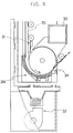
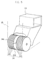
- a conventional apparatus for drying photo-sensitive material includes, as shown in Figs. 4 and 5, a transfer path 31 having a curved lower turn section 31a, a supply means 32 for supplying hot air provided outside the lower turn section 31a, and a suction duct 33 for sucking the hot air provided inside the lower turn section 31a.
- a drum-shaped lower roller 34 is rotatably arranged inside the lower turn section 31a.
- the lower roller 34 consists of a short column 34a on which outer circumference is bonded a foamed silicone layer 34c, and a plurality of disks 34b provided on the both sides of the column 34a with a suitable interval.
- the disk 34b is made of polyacetal (polyoxymethylene) and the like.
- the short column 34a and disk 34b are fixed to a common rotation shaft (not shown).
- the lower roller 34 is rotated by using a motor and the like to transfer a photo-sensitive material 35.
- the direction of the front side and rear side of the photo-sensitive material 35 is determined so that the surface of the emulsion of the photo-sensitive material faces to the outside of the lower turn section 31a.
- the hot air supplied from the supply means 32 is brown fowards the outside of the photo-sensitive material 35 (emulsion surface) to dry the photo-sensitive material 35.
- the hot air brown towards the outside of the photo-sensitive material 35 is sucked into the suction duct 33 through the gap between adjacent two disks 34b of the lower roller 34, thereby allowing the photo-sensitive material 35 to be sucked to the lower roller 34.
- the center portion of the photo-sensitive material 35 contacts with the foamed silicone layer 34c on the outer circumferential surface of the short column 34a so that it is possible to transfer the photo-sensitive material 35 without causing failure such as slippage.
- the photo-sensitive material 35 passing through the lower roller 34 is apt to be dried easily at the part contacting with the outer circumferential surface of the short column 34a or disk 34b because of easy heat transmission.
- the photo-sensitive material is apt not to be dried easily at the part other than that, namely, at the part passing through the gap between the adjacent two disks 34b.
- the present invention is made to solve the above problems, and accordingly it is an object of the present invention to provide a drying apparatus capable of preventing the generation of drying irregularity of the photo-sensitive material while maintaining easy transfer characteristics.
- an apparatus for drying photo-sensitive material comprising a transfer path for the photo-sensitive material having at least one curved section, a supply means for supplying hot air to the photo-sensitive material, and a suction duct for sucking the hot air provided inside the curved section, wherein the apparatus further includes a plurality of turn rollers provided along the inside of the curved section, and a paper guide having an opening for circulating hot air, provided between the adjacent two rollers of the plurality of turn rollers in such a manner as not to contact with the photo-sensitive material.
- the turn roller is equipped with a tube made of foamed silicone on a surface of a rotation shaft thereof.
- the photo-sensitive material is transferred with being guided along the transfer path by means of turn rollers and a paper guide arranged along the transfer path when drying the photo-sensitive material.
- the photo-sensitive material is dried with hot air supplied from the supply means. The hot air passing through the photo-sensitive material is sucked into the suction duct through the opening formed on the paper guide.
- the photo-sensitive material being dried contacts with the rollers along the entire width of the photo-sensitive material but does not contact with the paper guide. Therefore, it is possible to dry all the portions of the photo-sensitive material under a uniform condition, thereby causing no drying irregularity on the photo-sensitive material.
- Fig. 1 is a front view showing an embodiment of the drying apparatus of the present invention
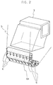
- Fig. 2 is a perspective view showing the main section of the drying apparatus in Fig. 1
- Fig. 3 is a perspective view showing the paper guide in Fig. 1.
- the drying apparatus shown in Figs. 1 and 2 have a transfer path 1 with a curved lower turn section 1a, a supplying means 2 for supplying hot air provided outside the lower turn section 1a, and a suction duct 3 for sucking the hot air provided inside the lower turn section 1a.
- the drying apparatus includes a plurality of turn rollers 4 provided along the inside of the lower turn section 1a, and a paper guide 6 having an opening 6a for circulating the hot air provided between the adjacent two rollers of the plurality of turn rollers 4 in such a manner as not to contact with the photo-sensitive material 5.
- 7 indicates a roller provided outside the lower turn section 1a
- 8 and 9 respectively indicate a transfer roller and a guide plate provided along the straight section of the transfer path 1 at suitable intervals.
- the supplying means 2 comprises a heater 2a, a blower 2b for forcibly supplying the air heated by the heater 2a and a duct 2c for distributing the hot air via the heater 2a to supply it to the photo-sensitive material 5.
- roller 4 there is used a cylindrical one having a relatively small diameter, for example about 35.6 mm. It is desirable to adopt a roller wherein a tube made of, for example, a foamed silicone with a thickness of about 13.8 mm is directly bonded on the surface of a rotation shaft because it offers a surface conditions suitable for transferring a photo-sensitive material, favorable dimensional accuracy, and less thermal contraction.
- a tube made of, for example, a foamed silicone with a thickness of about 13.8 mm is directly bonded on the surface of a rotation shaft because it offers a surface conditions suitable for transferring a photo-sensitive material, favorable dimensional accuracy, and less thermal contraction.
- the tube made of foamed silicone is manufactured by bonding the silicone tube to the shaft after the foamed silicone is formed into a tube-shape, and polishing the outer surface of the tube.
- the paper guide 6 is made of PPE (polyphenyleneether), etc., and, as shown in Fig. 3, is provided with a plurality of fins 6c for restricting the direction of the flow of hot air (an arrow P in Figure) inside the main body 6b, which is a hollow body and opened upward and downward, at suitable intervals.
- the fin 6c has a dent section 6e gauged out in an arc shape on the lower section so as not to contact with the photo-sensitive material 5 passing through the transfer path 1.
- both side section 6f of the fin 6c are formed in a curved shape to fit with the outside shape of the turn roller 4.
- An engaging section 6d is provided on the upper section of the paper guide 6 so as to engage with the fixed shaft (not shown) provided on the inner wall of the casing of the drying apparatus.
- the photo-sensitive material 5 is dried by supplying hot air from the supplying means 2 at the same time the photo-sensitive material is transferred. Moreover, the hot air is sucked into the suction duct 3 through the opening 6a provided on the paper guide 6 inside the lower turn section 1a. Therefore, the air pressure is reduced inside the lower turn section 1a compared with outside so that it is possible to transfer the photo-sensitive material 5 in a favorable state because the photo-sensitive material closely contact with the turn roller 4 side due to the difference in the inside and outside pressure of the lower turn section 1a.
- the photo-sensitive material 5 uniformly contact with the turn roller 4 along all the width of the photo-sensitive material 5, however, the lower portion of the paper guide 6 does not contact with the photo-sensitive material since it is set back to the inside of the lower turn section 1a. Therefore, it is possible to dry all the portions of the photo-sensitive material under a uniform condition.
- a dent section is formed on the fin of the paper guide so that the photo-sensitive material does not contact with the fin.
- the present invention is not limited to this, and it is acceptable that the fin is simply shortened or the whole paper guide is arranged separately from the transfer path.
- the present invention it is possible to dry all the portions of the photo-sensitive material under a uniform condition while maintaining the transfer characteristics so that no drying irregularity appears, thereby making it possible to prevent the reduction in the printing quality of the picture due to the drying irregularity.
Landscapes
- Engineering & Computer Science (AREA)
- Textile Engineering (AREA)
- Mechanical Engineering (AREA)
- General Engineering & Computer Science (AREA)
- Physics & Mathematics (AREA)
- General Physics & Mathematics (AREA)
- Photographic Processing Devices Using Wet Methods (AREA)
- Drying Of Solid Materials (AREA)
Applications Claiming Priority (3)
| Application Number | Priority Date | Filing Date | Title |
|---|---|---|---|
| JP219133/94 | 1994-09-13 | ||
| JP6219133A JP2914557B2 (ja) | 1994-09-13 | 1994-09-13 | 写真感光材料乾燥装置 |
| JP21913394 | 1994-09-13 |
Publications (3)
| Publication Number | Publication Date |
|---|---|
| EP0702267A2 true EP0702267A2 (fr) | 1996-03-20 |
| EP0702267A3 EP0702267A3 (fr) | 1997-08-20 |
| EP0702267B1 EP0702267B1 (fr) | 2001-04-11 |
Family
ID=16730755
Family Applications (1)
| Application Number | Title | Priority Date | Filing Date |
|---|---|---|---|
| EP95113977A Expired - Lifetime EP0702267B1 (fr) | 1994-09-13 | 1995-09-06 | Appareil pour sèches des matériaux photosensibles |
Country Status (4)
| Country | Link |
|---|---|
| US (1) | US5561913A (fr) |
| EP (1) | EP0702267B1 (fr) |
| JP (1) | JP2914557B2 (fr) |
| DE (1) | DE69520627T2 (fr) |
Cited By (1)
| Publication number | Priority date | Publication date | Assignee | Title |
|---|---|---|---|---|
| CN111879080A (zh) * | 2020-08-31 | 2020-11-03 | 陈金章 | 一种滚筒及滚筒烘干机 |
Families Citing this family (3)
| Publication number | Priority date | Publication date | Assignee | Title |
|---|---|---|---|---|
| US5689900A (en) * | 1995-08-21 | 1997-11-25 | Toshiba Battery Co., Ltd. | Drying apparatus and drying method |
| FI98944C (fi) * | 1995-10-25 | 1997-09-10 | Valmet Corp | Menetelmä ja laite paperiradan tai vastaavan päällysteen kuivatuksessa |
| US6058621A (en) * | 1998-06-05 | 2000-05-09 | Eastman Kodak Company | Apparatus and method for drying photosensitive material using radiant heat and air flow passages |
Family Cites Families (5)
| Publication number | Priority date | Publication date | Assignee | Title |
|---|---|---|---|---|
| US3403454A (en) * | 1967-04-05 | 1968-10-01 | White Consolidated Ind Inc | Heat treating apparatus for web and sheet material |
| DE3313876A1 (de) * | 1983-04-16 | 1984-10-18 | Agfa-Gevaert Ag, 5090 Leverkusen | Vorrichtung zum trocknen von fotografischen schichttraegern |
| JPS61238058A (ja) * | 1985-04-15 | 1986-10-23 | Fuji Photo Film Co Ltd | 写真処理装置用乾燥装置 |
| JPH03132660A (ja) * | 1989-10-19 | 1991-06-06 | Fuji Photo Film Co Ltd | 感光材料乾燥装置 |
| US5231774A (en) * | 1990-12-10 | 1993-08-03 | Fuji Photo Film Co., Ltd. | Photosensitive material drying apparatus |
-
1994
- 1994-09-13 JP JP6219133A patent/JP2914557B2/ja not_active Expired - Lifetime
-
1995
- 1995-09-06 EP EP95113977A patent/EP0702267B1/fr not_active Expired - Lifetime
- 1995-09-06 DE DE69520627T patent/DE69520627T2/de not_active Expired - Fee Related
- 1995-09-08 US US08/525,102 patent/US5561913A/en not_active Expired - Lifetime
Non-Patent Citations (1)
| Title |
|---|
| None |
Cited By (1)
| Publication number | Priority date | Publication date | Assignee | Title |
|---|---|---|---|---|
| CN111879080A (zh) * | 2020-08-31 | 2020-11-03 | 陈金章 | 一种滚筒及滚筒烘干机 |
Also Published As
| Publication number | Publication date |
|---|---|
| DE69520627T2 (de) | 2001-11-29 |
| EP0702267A3 (fr) | 1997-08-20 |
| DE69520627D1 (de) | 2001-05-17 |
| EP0702267B1 (fr) | 2001-04-11 |
| US5561913A (en) | 1996-10-08 |
| JPH0882912A (ja) | 1996-03-26 |
| JP2914557B2 (ja) | 1999-07-05 |
Similar Documents
| Publication | Publication Date | Title |
|---|---|---|
| US5561913A (en) | Apparatus for drying photo-sensitive material | |
| US4933724A (en) | Fixing device for electrophotography | |
| GB2079222A (en) | Fixing wet-type electrophotographic images | |
| JPH0635349A (ja) | 加熱加圧フュージングシステム | |
| EP0476694B1 (fr) | Méthode et dispositif de développement par la chaleur | |
| JPS6023054B2 (ja) | 連続紙の搬送装置 | |
| US5673908A (en) | Paper feeding apparatus | |
| JPH048439Y2 (fr) | ||
| US4136611A (en) | Electrostatic printing directly onto paper | |
| US7092665B2 (en) | Fixing apparatus having an exfoliating member and a restricting member | |
| JP3161483B2 (ja) | 定着装置用の搬送ガイド装置 | |
| JPH08310704A (ja) | 紙葉搬送装置 | |
| JP3272545B2 (ja) | 定着装置 | |
| JP3329763B2 (ja) | 熱現像装置 | |
| KR101282260B1 (ko) | 정착기 및 이를 포함하는 화상형성장치 | |
| JPH036911Y2 (fr) | ||
| JPH028301Y2 (fr) | ||
| JPH0515491Y2 (fr) | ||
| JP3917794B2 (ja) | 定着装置、画像形成装置 | |
| JP3152748B2 (ja) | トナー像記録装置の定着装置 | |
| US5835834A (en) | Fuser for fixing toner on recording paper with heat and pressure | |
| JP2631993B2 (ja) | 熱現像画形成装置 | |
| JPH071632Y2 (ja) | 乾燥装置 | |
| JP2684453B2 (ja) | 加熱現像装置 | |
| JPS58187970A (ja) | 密着加熱型定着装置における画像支持体のシワ防止装置 |
Legal Events
| Date | Code | Title | Description |
|---|---|---|---|
| PUAI | Public reference made under article 153(3) epc to a published international application that has entered the european phase |
Free format text: ORIGINAL CODE: 0009012 |
|
| AK | Designated contracting states |
Kind code of ref document: A2 Designated state(s): CH DE LI |
|
| 17P | Request for examination filed |
Effective date: 19961217 |
|
| PUAL | Search report despatched |
Free format text: ORIGINAL CODE: 0009013 |
|
| AK | Designated contracting states |
Kind code of ref document: A3 Designated state(s): CH DE LI |
|
| 17Q | First examination report despatched |
Effective date: 19980609 |
|
| GRAG | Despatch of communication of intention to grant |
Free format text: ORIGINAL CODE: EPIDOS AGRA |
|
| GRAG | Despatch of communication of intention to grant |
Free format text: ORIGINAL CODE: EPIDOS AGRA |
|
| GRAG | Despatch of communication of intention to grant |
Free format text: ORIGINAL CODE: EPIDOS AGRA |
|
| GRAH | Despatch of communication of intention to grant a patent |
Free format text: ORIGINAL CODE: EPIDOS IGRA |
|
| GRAH | Despatch of communication of intention to grant a patent |
Free format text: ORIGINAL CODE: EPIDOS IGRA |
|
| GRAA | (expected) grant |
Free format text: ORIGINAL CODE: 0009210 |
|
| AK | Designated contracting states |
Kind code of ref document: B1 Designated state(s): CH DE LI |
|
| PG25 | Lapsed in a contracting state [announced via postgrant information from national office to epo] |
Ref country code: LI Free format text: LAPSE BECAUSE OF FAILURE TO SUBMIT A TRANSLATION OF THE DESCRIPTION OR TO PAY THE FEE WITHIN THE PRESCRIBED TIME-LIMIT Effective date: 20010411 Ref country code: CH Free format text: LAPSE BECAUSE OF FAILURE TO SUBMIT A TRANSLATION OF THE DESCRIPTION OR TO PAY THE FEE WITHIN THE PRESCRIBED TIME-LIMIT Effective date: 20010411 |
|
| REG | Reference to a national code |
Ref country code: CH Ref legal event code: EP |
|
| REF | Corresponds to: |
Ref document number: 69520627 Country of ref document: DE Date of ref document: 20010517 |
|
| REG | Reference to a national code |
Ref country code: CH Ref legal event code: PL |
|
| PLBE | No opposition filed within time limit |
Free format text: ORIGINAL CODE: 0009261 |
|
| STAA | Information on the status of an ep patent application or granted ep patent |
Free format text: STATUS: NO OPPOSITION FILED WITHIN TIME LIMIT |
|
| 26N | No opposition filed | ||
| PGFP | Annual fee paid to national office [announced via postgrant information from national office to epo] |
Ref country code: DE Payment date: 20050902 Year of fee payment: 11 |
|
| PG25 | Lapsed in a contracting state [announced via postgrant information from national office to epo] |
Ref country code: DE Free format text: LAPSE BECAUSE OF NON-PAYMENT OF DUE FEES Effective date: 20070403 |