EP0702384A1 - Dreistellungsschalter - Google Patents
Dreistellungsschalter Download PDFInfo
- Publication number
- EP0702384A1 EP0702384A1 EP95906492A EP95906492A EP0702384A1 EP 0702384 A1 EP0702384 A1 EP 0702384A1 EP 95906492 A EP95906492 A EP 95906492A EP 95906492 A EP95906492 A EP 95906492A EP 0702384 A1 EP0702384 A1 EP 0702384A1
- Authority
- EP
- European Patent Office
- Prior art keywords
- switch
- push button
- normally
- pressed
- pressure
- Prior art date
- Legal status (The legal status is an assumption and is not a legal conclusion. Google has not performed a legal analysis and makes no representation as to the accuracy of the status listed.)
- Withdrawn
Links
Images


Classifications
-
- H—ELECTRICITY
- H01—ELECTRIC ELEMENTS
- H01H—ELECTRIC SWITCHES; RELAYS; SELECTORS; EMERGENCY PROTECTIVE DEVICES
- H01H13/00—Switches having rectilinearly-movable operating part or parts adapted for pushing or pulling in one direction only, e.g. push-button switch
- H01H13/50—Switches having rectilinearly-movable operating part or parts adapted for pushing or pulling in one direction only, e.g. push-button switch having a single operating member
- H01H13/64—Switches having rectilinearly-movable operating part or parts adapted for pushing or pulling in one direction only, e.g. push-button switch having a single operating member wherein the switch has more than two electrically distinguishable positions, e.g. multi-position push-button switches
-
- H—ELECTRICITY
- H01—ELECTRIC ELEMENTS
- H01H—ELECTRIC SWITCHES; RELAYS; SELECTORS; EMERGENCY PROTECTIVE DEVICES
- H01H13/00—Switches having rectilinearly-movable operating part or parts adapted for pushing or pulling in one direction only, e.g. push-button switch
- H01H13/50—Switches having rectilinearly-movable operating part or parts adapted for pushing or pulling in one direction only, e.g. push-button switch having a single operating member
- H01H13/506—Switches having rectilinearly-movable operating part or parts adapted for pushing or pulling in one direction only, e.g. push-button switch having a single operating member with a make-break action in a single operation
-
- H—ELECTRICITY
- H01—ELECTRIC ELEMENTS
- H01H—ELECTRIC SWITCHES; RELAYS; SELECTORS; EMERGENCY PROTECTIVE DEVICES
- H01H15/00—Switches having rectilinearly-movable operating part or parts adapted for actuation in opposite directions, e.g. slide switch
- H01H15/02—Details
- H01H15/06—Movable parts; Contacts mounted thereon
- H01H15/10—Operating parts
- H01H15/102—Operating parts comprising cam devices
-
- H—ELECTRICITY
- H01—ELECTRIC ELEMENTS
- H01H—ELECTRIC SWITCHES; RELAYS; SELECTORS; EMERGENCY PROTECTIVE DEVICES
- H01H2300/00—Orthogonal indexing scheme relating to electric switches, relays, selectors or emergency protective devices covered by H01H
- H01H2300/026—Application dead man switch: power must be interrupted on release of operating member
-
- H—ELECTRICITY
- H01—ELECTRIC ELEMENTS
- H01H—ELECTRIC SWITCHES; RELAYS; SELECTORS; EMERGENCY PROTECTIVE DEVICES
- H01H2300/00—Orthogonal indexing scheme relating to electric switches, relays, selectors or emergency protective devices covered by H01H
- H01H2300/028—Application dead man switch, i.e. power being interrupted by panic reaction of operator, e.g. further pressing down push button
Definitions
- This invention relates to a three-position switch. More specifically, this invention relates to a three-position switch which is employable for a double purpose including preparation for operation of a robot and emergency stop of a robot and which is mounted on an operation board employable for teaching a robot.
- a three-position switch is defined as a switch which is in an open or off position, when the push button thereof is not pressed or is in the free position, turns to a closed or on position, when the push button thereof is pressed with a moderate degree of pressure, and turns to an open or off position again, when the push button thereof is pressed with a large degree of pressure.
- An operation board employable for teaching a robot is usually designed to be held in the palm of a hand (usually a left hand) of an operater and the push buttons thereof are designed to be pressed with a finger of the other hand (usually a right hand) of the operater.
- a switch for preparation for operation of a robot is arranged on an operation board for teaching a robot at a location at which a finger of a hand (usually a left hand) which holds the operation board, automatically closes the switch, when the operation board is held in the palm of a hand. Therefore, a switch for preparation for operation of a robot is automatically brought to a ready position, when an operation board for teaching a robot is held with a hand of an operater.
- an operation board for teaching a robot is operable exclusively during a period in which the operation board is held with a hand (usually a left hand) and the switch for preparation for operation of a robot is automatically closed by a finger of the hand.
- an operation board for teaching a robot is not operable, during a period in which the operation board is not held with a hand (usually a left hand) and the switch for preparation for operation of a robot is open.
- a three-position switch is suitable for a switch which is employable for a double purpose including preparation for operation of a robot and emergency stop of a robot and which is mounted on an operation board employable for teaching a robot.
- a three-position switch is in an open position, while it is not held with a hand, turns to a closed position, when it is held with a hand and resultantly its switch for preparation for operation of a robot is pressed with a moderate degree of pressure, and turns to an open position again, when the holder thereof is surprised by an emergency and he grips the three-position switch with a large degree of pressure.
- the three-position switches available in the prior art are large in size and none of them can be employed as a switch which is employable for a double purpose including preparation for operation of a robot and emergency stop of a robot and which is mounted on an operation board employable for teaching a robot.
- a switch which is employable for a double purpose including preparation for operation of a robot and emergency stop of a robot and which is mounted on an operation board employable for teaching a robot is desired to be small enough to be held in the palm of a hand of an operater.
- the object of this invention is to provide a three-position switch which has a function to be in an open position, while the push button thereof is not pressed and the switch is in the free position, turns to a closed position, when the push button thereof is pressed with a moderate degree of pressure, and turns to an open position again, when the push button thereof is pressed with a large degree of pressure and which is small in size.
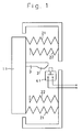
- a three-position switch in accordance with the first embodiment of this invention is provided a push button 11 elastically supported by a double spring 21 and 22, a switch operating rod 3 inwardly extending from the push button 11 in the direction approximately perpendicular to the push button 11 and having a lateral projection 31 projecting at the front end thereof, a normally-off switch 41 which operates in the direction approximately perpendicular to the direction in which the push button 11 moves and which turns to a closed position by a pressing action with a moderate degree of pressure of the push button 11, which pressing action causes the projection 31 to press the button of the normally-off switch 41 and which is in an open position, during the period in which the push button 11 is not pressed or is in the free position and during the period in which the push button 11 is pressed with a large degree of pressure.
- the foot of the projection 31 is preferably made large to make the operation of the normally-off switch 41 smooth.
- a three-position switch in accordance with the second embodiment of this invention is provided a push button 12 elastically supported by a spring 23, a combination of a normally-off switch 42 and a normally-on switch 43 which are connected in series to each other and which are arranged to face the push button 12, a normally-off switch operating means 5 which turns the normally-off switch 42 to a closed position, when the push button 12 is pressed with a moderate degree of pressure and when the push button 12 is pressed with a large degree of pressure, and a normally-on switch operating means 6 which turns the normally-on switch 43 to an open position, when the push button 12 is pressed with a large degree of pressure.
- a push button 11 is a bar.
- the reason why the push button 11 is a bar is to enable one hand of an operater to hold the three-position switch in the palm of his hand, when the three-position switch is employed as a switch for preparation for operation of a robot and for emergency stop of a robot and which is mounted on an operation board for teaching a robot.
- the push button of a bar 11 is elastically supported by a double spring, so that it is suspended in the free position.
- the double spring consists of a weak spring 21 and a strong spring 22 both of which are wound on a single bobbin. When the double spring is pressed with a moderate degree of pressure, the weak spring 21 deforms, and when the double spring is pressed with a large degree of pressure, the both springs 21 and 22 deform.
- a switching rod 3 inwardly extends from the push button 11 in the direction approximately perpendicular to the push button 11 and has a projection 31 which laterally projects at the front end thereof.
- the projection 31 has a shape of trapezoid, so that the move of a normally-off switch 41 to be referred to later is made smooth.
- the normally-off switch 41 turns to a closed position exclusively when the push button 11 is pressed with a moderate degree of pressure to cause the projection 31 to press a button of the normally-off switch 31.
- the button of the normally-off switch 41 preferably has a shape of trapezoid for the purpose to make the move of the normally-off switch 41 smooth.
- Fig. 1 illustrates the free position in which the push button 11 is not pressed. In this position, the normally-off switch 41 is in an open position.
- the normally-off switch 41 turns to a closed position, when the push button 11 is pressed with a moderate degree of pressure.
- the normally-off switch 41 turns to an open position again, when the push button 11 is pressed with a large degree of pressure.
- a three-position switch in accordance with the first embodiment of this invention has a function to be in an open position, when the push button thereof is not pressed, to be in a closed position, when the push button thereof is pressed with a moderate degree of pressure, and to be in an open position again, when the push button thereof is pressed with a large degree of pressure, and is small in size. Therefore, the three-position switch in accordance with the first embodiment of this invention can be employed as a switch employable for a double purpose including preparation for operation of a robot and emergency stop of a robot and which is mounted on an operation board for teaching a robot.
- a push button 12 is a bar.
- the reason why the push button 12 is a bar is to enable one hand of an operater to hold the three-position switch in the palm of his hand, when the three-position switch is employed as a switch which is employable for preparation for operation of a robot and for emergency stop of a robot and which is mounted on an operation board for teaching a robot and to make it possible to operate two independent switches with one push button.
- the push button 12 is elastically supported by a spring 23.
- a normally-off switch 42 and a normally-on switch 43 are connected in series to each other. This series circuit is in an open position, while the push button 12 is not pressed.
- a normally-off switch operating means 5 is a spring having a long operating span.
- the normally-off switch operating means 5 keeps the normally-off switch 42 in a closed position, during the period in which the push button 12 is pressed with a moderate degree of pressure and during the period in which the push button 12 is pressed with a large degree of pressure.
- a normally-on switch operating means 6 is a projection projected from the push button 12.
- the normally-on switch operating means 6 turns the normally-on switch 43 to an open position, when the push button 12 is pressed with a large degree of pressure.
- a three-position switch in accordance with the second embodiment of this invention has a function to be in an open position, when the push button thereof is not pressed, to be in a closed position, when the push button thereof is pressed with a moderate degree of pressure, and to be in an open position again, when the push button thereof is pressed with a large degree of pressure, and is small in size. Therefore, the three-position switch in accordance with the second embodiment of this invention can be employed as a switch employable for a double purpose including preparation for operation of a robot and emergency stop of a robot and which is mounted on an operation board employable for teaching a robot.
- either of the three-position switches in accordance with this invention has a function to be in an open position, when the push button thereof is not pressed, to be in a closed position, when the push button thereof is pressed with a moderate degree of pressure, and to be in an open position again, when the push button thereof is pressed with a large degree of pressure, and is small in size. Therefore, either of the three-position switches in accordance with this invention can be employed as a switch employable for a double purpose including preparation for operation of a robot and emergency stop of a robot and which is mounted on an operation board employable for teaching a robot.
Landscapes
- Push-Button Switches (AREA)
- Switch Cases, Indication, And Locking (AREA)
Applications Claiming Priority (3)
| Application Number | Priority Date | Filing Date | Title |
|---|---|---|---|
| JP4718594A JPH07262865A (ja) | 1994-03-17 | 1994-03-17 | 3ポジションスイッチ |
| JP47185/94 | 1994-03-17 | ||
| PCT/JP1995/000053 WO1995025333A1 (en) | 1994-03-17 | 1995-01-20 | Three-position switch |
Publications (1)
| Publication Number | Publication Date |
|---|---|
| EP0702384A1 true EP0702384A1 (de) | 1996-03-20 |
Family
ID=12768049
Family Applications (1)
| Application Number | Title | Priority Date | Filing Date |
|---|---|---|---|
| EP95906492A Withdrawn EP0702384A1 (de) | 1994-03-17 | 1995-01-20 | Dreistellungsschalter |
Country Status (3)
| Country | Link |
|---|---|
| EP (1) | EP0702384A1 (de) |
| JP (1) | JPH07262865A (de) |
| WO (1) | WO1995025333A1 (de) |
Cited By (8)
| Publication number | Priority date | Publication date | Assignee | Title |
|---|---|---|---|---|
| EP1014406A4 (de) * | 1997-04-28 | 2000-06-28 | Idec Izumi Corp | Tastschalter, vorrichtung zum betrieb und tastatur mit diesem schalter |
| WO2003012809A1 (de) * | 2001-07-31 | 2003-02-13 | Keba Ag | Sicherheitsschalteinrichtung für elektrisch gesteuerte maschinen |
| US6627830B2 (en) | 2000-07-31 | 2003-09-30 | Idec Izumi Corporation | Push button and teaching pendant with the push button |
| EP1898435A3 (de) * | 2006-09-06 | 2008-06-04 | Omron Corporation | Schalter und Kontaktmodule dafür |
| WO2009046935A1 (de) * | 2007-10-02 | 2009-04-16 | Georg Schlegel Gmbh & Co. Kg | Schalter mit zwei über koppelmittel miteinander in verbindung stehenden kontakteinrichtungen |
| AT505374B1 (de) * | 2007-05-24 | 2011-11-15 | Blum Gmbh Julius | Antriebsvorrichtung für ein bewegbares möbelteil |
| US8278574B2 (en) | 2007-05-24 | 2012-10-02 | Julius Blum Gmbh | Switch element for a movable furniture part |
| GR1010672B (el) * | 2023-03-02 | 2024-04-22 | Κωνσταντινος Κωνιος | Διακοπτης με ενσωματωμενη λειτουργια εκτακτης αναγκης |
Families Citing this family (9)
| Publication number | Priority date | Publication date | Assignee | Title |
|---|---|---|---|---|
| JP2001198337A (ja) * | 2000-01-20 | 2001-07-24 | Chukyo Yugi:Kk | パチンコ機のパチンコ球補給装置 |
| JP2003187671A (ja) | 2001-12-14 | 2003-07-04 | Nec Saitama Ltd | キー入力回路、及び、携帯端末の入力装置 |
| JP2006338830A (ja) * | 2005-06-03 | 2006-12-14 | Kenwood Corp | データ再生装置、データ再生方法、および、プログラム |
| US7439463B2 (en) * | 2006-01-17 | 2008-10-21 | Dentsply International Inc. | Foot switch for activating a dental or medical treatment apparatus |
| JP4545802B2 (ja) * | 2008-01-21 | 2010-09-15 | Idec株式会社 | 押ボタンスイッチ及びこれを用いた操作装置並びに教示ペンダント |
| JP2011138620A (ja) * | 2008-04-21 | 2011-07-14 | Mitsubishi Electric Corp | スイッチの操作装置 |
| US20130042943A1 (en) | 2011-08-18 | 2013-02-21 | Countlab, Inc. | Container filling machine |
| US9434487B2 (en) | 2011-09-30 | 2016-09-06 | Countlab, Inc | Container filling machine |
| CN117769752A (zh) * | 2021-08-30 | 2024-03-26 | Idec株式会社 | 使能开关 |
Family Cites Families (5)
| Publication number | Priority date | Publication date | Assignee | Title |
|---|---|---|---|---|
| JPS59194235U (ja) * | 1983-06-10 | 1984-12-24 | エスエムケイ株式会社 | 押しボタンスイツチ |
| JPH0633624Y2 (ja) * | 1986-09-02 | 1994-08-31 | オムロン株式会社 | スイツチ |
| JPH0524101Y2 (de) * | 1986-11-19 | 1993-06-18 | ||
| JPS6387735U (de) * | 1986-11-27 | 1988-06-08 | ||
| JPH03116628U (de) * | 1990-03-12 | 1991-12-03 |
-
1994
- 1994-03-17 JP JP4718594A patent/JPH07262865A/ja active Pending
-
1995
- 1995-01-20 WO PCT/JP1995/000053 patent/WO1995025333A1/ja not_active Ceased
- 1995-01-20 EP EP95906492A patent/EP0702384A1/de not_active Withdrawn
Non-Patent Citations (1)
| Title |
|---|
| See references of WO9525333A1 * |
Cited By (14)
| Publication number | Priority date | Publication date | Assignee | Title |
|---|---|---|---|---|
| EP1398809A1 (de) * | 1997-04-28 | 2004-03-17 | Idec Izumi Corporation | Tastschalter, Vorrichtung zum Betrieb und Tastatur mit diesem Schalter |
| US6288352B1 (en) | 1997-04-28 | 2001-09-11 | Idec Izuni Corporation | Push-button switch, and operation device and teaching pendant comprising the same |
| EP1014406A4 (de) * | 1997-04-28 | 2000-06-28 | Idec Izumi Corp | Tastschalter, vorrichtung zum betrieb und tastatur mit diesem schalter |
| EP1387373A3 (de) * | 1997-04-28 | 2004-02-11 | Idec Izumi Corporation | Tastschalter, Vorrichtung zum Betrieb und Tastatur mit diesem Schalter |
| US6627830B2 (en) | 2000-07-31 | 2003-09-30 | Idec Izumi Corporation | Push button and teaching pendant with the push button |
| US7176399B2 (en) | 2001-07-31 | 2007-02-13 | Keba Ag | Safety switch device for electrically controlled machines |
| WO2003012809A1 (de) * | 2001-07-31 | 2003-02-13 | Keba Ag | Sicherheitsschalteinrichtung für elektrisch gesteuerte maschinen |
| DE10297207B4 (de) * | 2001-07-31 | 2007-11-08 | Keba Ag | Sicherheitsschalteinrichtung für elektrisch gesteuerte Maschinen |
| EP1898435A3 (de) * | 2006-09-06 | 2008-06-04 | Omron Corporation | Schalter und Kontaktmodule dafür |
| US7585183B2 (en) | 2006-09-06 | 2009-09-08 | Omron Corporation | Switch with a plurality of contact modules |
| AT505374B1 (de) * | 2007-05-24 | 2011-11-15 | Blum Gmbh Julius | Antriebsvorrichtung für ein bewegbares möbelteil |
| US8278574B2 (en) | 2007-05-24 | 2012-10-02 | Julius Blum Gmbh | Switch element for a movable furniture part |
| WO2009046935A1 (de) * | 2007-10-02 | 2009-04-16 | Georg Schlegel Gmbh & Co. Kg | Schalter mit zwei über koppelmittel miteinander in verbindung stehenden kontakteinrichtungen |
| GR1010672B (el) * | 2023-03-02 | 2024-04-22 | Κωνσταντινος Κωνιος | Διακοπτης με ενσωματωμενη λειτουργια εκτακτης αναγκης |
Also Published As
| Publication number | Publication date |
|---|---|
| JPH07262865A (ja) | 1995-10-13 |
| WO1995025333A1 (en) | 1995-09-21 |
Similar Documents
| Publication | Publication Date | Title |
|---|---|---|
| EP0702384A1 (de) | Dreistellungsschalter | |
| CA2306855A1 (en) | Ratchet wrench | |
| US6180898B1 (en) | Emergency stop switching mechanism for robot and teaching control panel provided with same | |
| JPH1177579A (ja) | ロボット非常停止用スイッチ機構並びに該機構を設けた教示操作盤 | |
| US6920666B1 (en) | Control mechanism of a pull rod | |
| US4831349A (en) | Switching device | |
| JPH0795409B2 (ja) | オンオフ動作スイッチの制御装置 | |
| JPH02113241U (de) | ||
| JPH0521794Y2 (de) | ||
| JPH035401U (de) | ||
| WO2003010786A1 (en) | Input unit with switch | |
| EP0314925A3 (en) | Microswitch | |
| JPH0246335U (de) | ||
| JPS597705Y2 (ja) | 複合スイツチ装置 | |
| JP2002150875A (ja) | スイッチ装置とこのスイッチ装置を用いたセーフティ装置 | |
| JPS60130547U (ja) | リモ−トコントロ−ル式回路しや断器 | |
| JPH03110732U (de) | ||
| JPS5818829A (ja) | 電磁スイツチ | |
| JPH061199Y2 (ja) | ラジコン用送信機のスティック機構 | |
| JPH04128184U (ja) | 電気機器の安全装置 | |
| JPS5916019U (ja) | 自照式プツシユボタン装置 | |
| JPH0316624U (de) | ||
| JPH038047B2 (de) | ||
| JPH0188419U (de) | ||
| JP2002203453A (ja) | 押しボタンスイッチ |
Legal Events
| Date | Code | Title | Description |
|---|---|---|---|
| PUAI | Public reference made under article 153(3) epc to a published international application that has entered the european phase |
Free format text: ORIGINAL CODE: 0009012 |
|
| 17P | Request for examination filed |
Effective date: 19951201 |
|
| AK | Designated contracting states |
Kind code of ref document: A1 Designated state(s): DE IT SE |
|
| STAA | Information on the status of an ep patent application or granted ep patent |
Free format text: STATUS: THE APPLICATION HAS BEEN WITHDRAWN |
|
| 18W | Application withdrawn |
Withdrawal date: 19960912 |