EP0702906B1 - Paire d'articulations à manoeuvres synchronisées pour la fixation d'une visière escamotable sur un casque - Google Patents
Paire d'articulations à manoeuvres synchronisées pour la fixation d'une visière escamotable sur un casque Download PDFInfo
- Publication number
- EP0702906B1 EP0702906B1 EP95402088A EP95402088A EP0702906B1 EP 0702906 B1 EP0702906 B1 EP 0702906B1 EP 95402088 A EP95402088 A EP 95402088A EP 95402088 A EP95402088 A EP 95402088A EP 0702906 B1 EP0702906 B1 EP 0702906B1
- Authority
- EP
- European Patent Office
- Prior art keywords
- helmet
- visor
- hinges
- pair
- pin
- Prior art date
- Legal status (The legal status is an assumption and is not a legal conclusion. Google has not performed a legal analysis and makes no representation as to the accuracy of the status listed.)
- Expired - Lifetime
Links
- 230000001360 synchronised effect Effects 0.000 title claims description 4
- 238000007373 indentation Methods 0.000 claims 1
- 230000003287 optical effect Effects 0.000 description 6
- BASFCYQUMIYNBI-UHFFFAOYSA-N platinum Chemical compound [Pt] BASFCYQUMIYNBI-UHFFFAOYSA-N 0.000 description 4
- 238000003032 molecular docking Methods 0.000 description 3
- 238000012423 maintenance Methods 0.000 description 2
- 210000003625 skull Anatomy 0.000 description 2
- 235000005921 Cynara humilis Nutrition 0.000 description 1
- 240000002228 Cynara humilis Species 0.000 description 1
- 238000012550 audit Methods 0.000 description 1
- 230000000295 complement effect Effects 0.000 description 1
- 239000000428 dust Substances 0.000 description 1
- -1 light Substances 0.000 description 1
- 230000002093 peripheral effect Effects 0.000 description 1
- 229910052697 platinum Inorganic materials 0.000 description 1
- 230000001681 protective effect Effects 0.000 description 1
- 238000007789 sealing Methods 0.000 description 1
- 239000000126 substance Substances 0.000 description 1
- 230000000007 visual effect Effects 0.000 description 1
Images



Classifications
-
- A—HUMAN NECESSITIES
- A42—HEADWEAR
- A42B—HATS; HEAD COVERINGS
- A42B3/00—Helmets; Helmet covers ; Other protective head coverings
- A42B3/04—Parts, details or accessories of helmets
- A42B3/18—Face protection devices
- A42B3/22—Visors
Definitions
- the present invention relates to an articulated fixing for a visor helmet that can be operated with one hand while allowing tilting of the visor relative to the helmet from a position folded over the face to a raised position revealing the face and inversely according to a complex movement starting with a translation moving the visor away from the helmet in order to release it from a possible seal or ledge and continuing to the raised position with a rotation retracting the visor above the face.
- Visor helmets are used to protect the head of a pilot in the event of an impact.
- the helmet protects the skull while the visor protects the face and is used for visual comfort in an aggressive atmosphere: wind, dust, light, fog ... and possibly protection of the environment aggressive chemical.
- sealing must be ensured between the helmet shell and the visor in the folded position. This requires the presence of a peripheral seal and imposes a frontal docking on the visor causing the latter a tilting movement that does not not limited to a simple rotation and which can no longer be obtained by a direct manipulation of the visor because such manipulation would require the controls a complex movement requiring both hands.
- helmets are equipped with a helmet sight which is an optical image projection system using a semi-reflecting area visor in the folded position to display in front of the eyes of the driver's driving aid symbols. This requires very precise and excellent reproducibility of the visor position by compared to the other optical elements worn by the helmet.
- a device comprising the characteristics of the preamble of the claim 1 is known from WO-A-87/04323.
- the object of the present invention is an articulated fixing of a visor on a helmet which gives the visor a movement of complex tilting based on translation and rotation, and which is can be operated directly by the helmet wearer, with one hand, by simple rotation of a joystick, without requiring motor assistance electric.
- mechanical means of synchronization include: a cable which slides in a sheath connecting the two joints following the outline of the helmet shell and which is equipped with its two ends of a rack, and two toothed pinions integral with the pivot pins and crank pins of the joints that mesh with the racks so that a rotational movement of a crankpin causes the cable to slide in its sheath and a movement of identical rotation of the other crankpin.
- the pinions and racks are then mounted in gear boxes housed at the base of each joint.
- the handles have the shape of a shell having on its outer face depressions facilitating their gripping.
- the helmet has a protective shell 1 enveloping the skull with the exception of the face.
- This shell 1 is closed at the front by a fairing 2 in its lower part and by a visor 3 in its upper part.
- the visor 3 is articulated laterally to the shell 1 of the helmet so that it can be lowered or raised, the visor being operated by means of a lever 4 covering each joint.
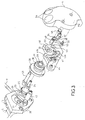
- the shell 1 of the helmet contains, as shown in FIG. 2, a hoop-shaped plate 5 which supports an image-generating tube 6 associated with an optical image projection system 7 on a semi-reflecting area of the visor and the hinges 8 for fixing the visor 3.
- the image generator tube 6 and the associated optical system 7 are mount on the plate 5 by means of lugs 10, 11 fitting onto tabs placed one 12 at the top of the plate 5, the other 13 on the back of the articulation support 8.
- the joints 8 for attaching the visor 3 to the helmet are mounted at the ends of the arch of the plate 5, at the temples wearing a helmet and joined together by a sheathed cable 9 of motion synchronization.
- This facilitates adjustments the respective positions of the elements of the optical system of image projection, avoids the problems posed by the lack of rigidity of the helmet shell 1 on the stability of the adjustment of the relative positions of the visor and other elements of the optical image projection system and simplifies maintenance of the helmet visor.
- Each end of the arch of the plate 5 ends substantially vertically by an ear 20 pierced with a median hole 21 for a horizontal pivot axis 22 having a flattened circular head 23 extended by a rod 24.
- the pivot axis 22 is threaded into the hole 21 of the ear 20 from the inside. Its circular head 23 is pressed against the rear wall of the ear 20 while its rod 24 protrudes horizontally from the front wall of the ear in a gearbox.
- a cover 28 of the box gear is threaded on the pivot axis 22 to close the box gear and secure the pinion 25 and the rack 26.
- This cover 28 has an extension on the outside tubular 29 serving as a hinge axis surrounded by an annular plate 30 serving as a bearing for the joint.
- the first and second washers 31, 33 serve as shims thick. They are peelable. By adjusting their individual thicknesses while keeping them a constant overall thickness, we can vary the lateral position of the lug 32 of the visor relative to the plate 5 for fine transverse adjustment of the visor position by compared to the helmet which is useful for adjusting the system elements image projection optics.
- the lateral attachment tab 32 of the visor is threaded on the tubular extension 29 of the cover 28 of the gearbox surrounding the rod of the pivot axis 22 through a hole 40 in the form of buttonhole whose width determines the amplitude of the travel in translation of the visor relative to the helmet. It has a cam-shaped notch 41 in which a guide finger slides 42 fixed to the outer wall of the gearbox and integral with the wall side of the helmet to define the components in translation and rotation of the tilting movement of the visor relative to the helmet.
- This notch 41 has a part in an arc 41a defining the rotational movement to bring the visor from its position retracted to its folded position, extended by a straight portion 41b almost radial towards the outside of the part in an arc 41a, of same width and orientation as the buttonhole, defining the translational movement to bring the visor closer to the helmet to ensure its docking when it is folded down.
- the lateral attachment tab 32 of the visor also has a ovalized hole 43 for its mechanical drive by the crankpin 34 and a flange 44 for its attachment to the visor 3. As can be seen in FIG. 2, the flange 44 is screwed to an intermediate piece 45 riveted to the visor.
- the crankpin 34 is screwed onto the end of the rod 24 of the axis of pivot thanks to a screw 46 so as to be integral in rotation with the latter like the toothed pinion 25. It has a main arm 47 which ends by a lug 48 for training which is turned towards the lateral attachment tab 32 and which struggles in the ovalized hole 42 and two auxiliary arms arranged star, one 49 for fixing a shell-shaped handle 4 allowing the crankpin 34 to be operated by hand, the other 50 for fixing a spring recalling the crankpin 34 in its extreme positrons of travel corresponding to the folded and retracted positions of the visor 3.
- the tension spring recalling the crankpin 34 in its positions extremes is visible in Figures 4 to 6. It is a tension spring 51 bearing between a lug 52 of the auxiliary arm 50 of the crankpin 34 turned inward of lever 4 and a fixed pin 53 attached to the outer wall of the gearbox.
- the handle 4 has a shell shape adapted to the shape of the palm with depressions 54 for the fingertips which makes it easy to manipulate blind.
- Figure 4 shows, front views, the respective positions of the crankpin 34, side lug 32 of visor and spring traction 51 when the visor 3 is in the folded position.
- the guide finger 42 is located at the straight end of the notch 41, the actuating lug 48 crankpin at the top of the ovalized hole 43 of the side lug 32 and the pivot axis 22 at the far left of the buttonhole hole 40, on the side of notch 41.
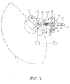
- Figure 5 shows, still viewed from the front, the positions respective of the crankpin 34, the lateral attachment tab 32 and the spring of traction 51 when the visor is in an intermediate folded position but already moved away from the rim of the helmet.
- the guide finger 42 is located at the junction of the rectilinear and circular parts of the notch 41, the lug of maneuver 48 of the crankpin at the base of the ovalized hole 43 of the lug lateral 32 and the pivot axis 22 at the extreme right of the buttonhole hole 40 on the side opposite notch 41.
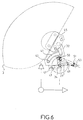
- Figure 6 shows, still viewed from the front, the respective positions crankpin 34, side lug 32 and tension spring 51 when the visor is in the retracted position above the face.
- Finger guide 42 is at the end of the circular part of the notch 41, the lug 48 of the crank pin remaining at the base of the ovalized hole 43 and pivot axis 22 to the far right of the buttonhole hole 40 on the opposite side at notch 41.
- crank pin 34 When a rotational movement is imposed manually on the lever 4, it drives the crank pin 34 and the toothed pinion 25 in rotation.
- the crankpin 34 causes the lateral attachment tab 32 to tilt and therefore of the visor 3 according to a complex movement of rotation and translation determined by guiding the finger 42 in the notch 41 while that the toothed pinion 25 moves the rack 26 driving the cable in translation in its sheath 27.
- the cable moves the rack on the other joint which then rotates the toothed pinion and the crankpin on the other joint which is then actuated in synchronism without the need to use his controller.
Landscapes
- Helmets And Other Head Coverings (AREA)
- Pivots And Pivotal Connections (AREA)
Description
- un axe de pivot pivotant autour d'un axe solidaire de la paroi latérale du casque ;
- une patte d'attache latérale de la visière enfilée sur l'axe de pivot grâce à un trou en forme de boutonnière dont la largeur autorise, en sus d'un mouvement de rotation, un débattement de la visière en translation par rapport au casque et pourvue d'une encoche en forme de came dans laquelle coulisse un doigt solidaire de la paroi latérale du casque pour guider en translation et en rotation la visière au cours de son basculement par rapport au casque ;
- un maneton rotatif fixé à l'axe de pivot venant en prise dans un trou ovalisé de la patte d'attache de manière à entraíner, par son mouvement de rotation avec l'axe de pivot, le basculement de ladite patte d'attache ;
- une manette fixée audit maneton sur l'extérieur de l'articulation pour permettre sa rotation à la main ; et
- des moyens de rappel élastique rappelant le maneton dans les positions extrêmes de sa plage de débattement en rotation ;
- une figure 1 représente un casque de pilote équipé d'une paire d'articulations conformes à l'invention ;
- une figure 2 représente, en perspective démontée, une platine support de viseur de casque qui est destinée à être attachée à l'intérieur de la coque du casque, les articulations de fixation de la visière et un viseur de casque qui viennent se monter sur la platine ;
- une figure 3 représente, en perspective démontée, une articulation de fixation de la visière au casque conforme à l'invention ; et
- des figures 4, 5 et 6 représentent, vues de face, les positions respectives des pièces principales d'une articulation au cours des différentes phases du mouvement de basculement de la visière.
Claims (5)
- Paire d'articulations à manoeuvres synchronisées pour la fixation d'une visière (3) escamotable sur un casque comprenantet en ce qu'elles sont couplées par des moyens mécaniques de synchronisation (25,26,27) synchronisant les mouvements de leurs manetons (34).un axe de pivot (22) pivotant autour d'un axe solidaire de la paroi latérale du casque caractérisées en ce qu'elles comportent chacune:une patte d'attache latérale (32) de la visière (3) enfilée sur l'axe de pivot (22) grâce à un trou en forme de boutonnière (40) dont la largeur autorise, en sus d'un mouvement de rotation, un débattement de la visière (3) en translation par rapport au casque (1) et pourvue d'une encoche (41) en forme dé came dans laquelle coulisse un doigt (42) solidaire de la paroi latérale du casque pour guider en translation et en rotation la visière (3) au cours de son basculement par rapport au casque ;un maneton rotatif (34) fixé à l'axe de pivot (22) venant en prise dans un trou ovalisé (43) de la patte d'attache (32) de manière à entraíner, par son mouvement de rotation avec l'axe de pivot (22), le basculement de ladite patte d'attache (32) ;une manette (4) fixée audit maneton (34) sur l'extérieur de l'articulation pour permettre sa rotation à la main ; etdes moyens de rappel élastique (51) rappelant le maneton (34) dans les positions extrêmes de sa plage de débattement en rotation ;
- Paire d'articulations selon la revendication 1, caractérisées en ce que les moyens mécaniques de synchronisation comportent : un câble qui coulisse dans une gaine (9) reliant les deux articulations en suivant le contour de la coque (1) du casque et qui est équipé à ses deux extrémités d'une crémaillère (26), et deux pignons dentés (25) solidaires des axes de pivot (22) et des manetons (34) des articulations qui s'engrènent avec les crémaillères (26) de manière qu'un mouvement de rotation d'un maneton (34) des articulations qui s'engrènent avec les crémaillères (26) de manière qu'un mouvement de rotation d'un maneton (34) provoque un coulissement du câble dans sa gaine (27) et un mouvement de rotation identique de l'autre maneton.
- Paire d'articulations selon la revendication 1, caractérisées en ce que lesdits pignons (25) et crémaillères (26) sont montés dans une boíte d'engrenage logée à la base de chaque articulation.
- Paire d'articulations selon la revendication 1, caractérisées en ce que ladite manette (4) a la forme d'une coquille présentant sur sa face extérieure des dépressions pour la pointe des doigts facilitant sa préhension.
- Paire d'articulations selon la revendication 1, caractérisées en ce que lesdits moyens de rappel élastique rappelant le maneton (34) dans les positions extrêmes de sa plage de débattement en rotation comporte un ressort de traction (51) attaché entre un ergot (52) d'un bras auxiliaire du maneton 34) et un pion fixe (53) solidaire de la paroi latérale du casque.
Applications Claiming Priority (2)
| Application Number | Priority Date | Filing Date | Title |
|---|---|---|---|
| FR9411176 | 1994-09-20 | ||
| FR9411176A FR2724541B1 (fr) | 1994-09-20 | 1994-09-20 | Paire d'articulations a manoeuvres synchronisees pour la fixation d'une visiere escamotable sur un casque |
Publications (2)
| Publication Number | Publication Date |
|---|---|
| EP0702906A1 EP0702906A1 (fr) | 1996-03-27 |
| EP0702906B1 true EP0702906B1 (fr) | 1998-11-18 |
Family
ID=9467078
Family Applications (1)
| Application Number | Title | Priority Date | Filing Date |
|---|---|---|---|
| EP95402088A Expired - Lifetime EP0702906B1 (fr) | 1994-09-20 | 1995-09-15 | Paire d'articulations à manoeuvres synchronisées pour la fixation d'une visière escamotable sur un casque |
Country Status (7)
| Country | Link |
|---|---|
| US (1) | US5604930A (fr) |
| EP (1) | EP0702906B1 (fr) |
| JP (1) | JPH08170212A (fr) |
| CA (1) | CA2158620A1 (fr) |
| DE (1) | DE69506067T2 (fr) |
| FR (1) | FR2724541B1 (fr) |
| IL (1) | IL115326A (fr) |
Families Citing this family (19)
| Publication number | Priority date | Publication date | Assignee | Title |
|---|---|---|---|---|
| GB2303872B (en) * | 1995-08-01 | 1999-01-20 | Gec Marconi Avionics Holdings | Helmet visor release apparatus |
| US5901369A (en) * | 1997-08-15 | 1999-05-11 | Honeywell Inc. | Headgear having an articulated mounting mechanism for a visor |
| FI982681A0 (fi) * | 1998-12-11 | 1998-12-11 | Arimo Ristola | Kiinnityssovitelma suojaimien kiinnittämiseksi kypärään |
| FR2817713B1 (fr) * | 2000-12-12 | 2003-11-28 | Thomson Csf | Casque a visieres escamotables a reconfiguration rapide jour/nuit |
| JP3875650B2 (ja) * | 2002-07-30 | 2007-01-31 | 株式会社アライヘルメット | フルフェースヘルメットにおけるマウスシャッタの支持構造 |
| US7895678B2 (en) * | 2007-08-06 | 2011-03-01 | Bell Sports, Inc. | Helmet with improved shield mount and precision shield control |
| US8214920B1 (en) * | 2008-02-18 | 2012-07-10 | Sperian Eye & Face Protection, Inc. | Hard hat adapter for a welding helmet |
| US8291513B2 (en) * | 2009-04-18 | 2012-10-23 | Stephen John Prinkey | Counter balanced, hands free, self positioning, protective shield |
| DE102010027015A1 (de) * | 2010-07-13 | 2012-01-19 | Anton Pfanner | Gesichtsschutz zur Befestigung an einem Schutzhelm, insbesondere für Forstarbeiter |
| US9125447B2 (en) | 2010-09-20 | 2015-09-08 | Revision Military S.A.R.L. | Helmet attachment mechanism for visor |
| US8813270B2 (en) * | 2011-07-26 | 2014-08-26 | Vladimiro Pizzi | Helmet with flush aligned shield when closed |
| ITVR20120022A1 (it) * | 2012-02-20 | 2013-08-21 | Agv Spa | Dispositivo di movimentazione per un casco per muovere un primo elemento del casco rispetto ad un secondo elemento del casco. |
| US8701212B2 (en) | 2012-09-26 | 2014-04-22 | 3M Innovative Properties Company | Elongated guide, and visor removably mountable thereto |
| US9775397B2 (en) | 2013-03-15 | 2017-10-03 | 3M Innovative Properties Company | Elongated guide, and visor removably mountable thereto |
| US11134741B2 (en) * | 2017-05-25 | 2021-10-05 | E.D. Bullard Company | Protective helmet with a retractable and removable visor |
| US10786032B2 (en) * | 2019-01-18 | 2020-09-29 | Cookie Composites Group Pty Ltd. | Skydiving helmet and visor mounting system |
| US11213089B2 (en) | 2019-06-04 | 2022-01-04 | Msa Technology, Llc | Protective helmet with face protection shield and linkage mechanism |
| IT202200027348A1 (it) * | 2022-12-30 | 2024-06-30 | Dainese Spa | Casco di protezione |
| KR102878214B1 (ko) * | 2024-05-07 | 2025-10-29 | (주)에이치제이씨 | 헬멧 |
Family Cites Families (14)
| Publication number | Priority date | Publication date | Assignee | Title |
|---|---|---|---|---|
| US3050735A (en) * | 1958-03-28 | 1962-08-28 | Redwing Ltd | Apparatus for automatically pivoting a hinged closure into closed position |
| US3128469A (en) * | 1959-08-06 | 1964-04-14 | Ml Aviation Co Ltd | Flying helmets |
| GB1119409A (en) * | 1965-11-09 | 1968-07-10 | Ml Aviation Co Ltd | Improvements relating to flying helmets |
| US3473166A (en) * | 1968-01-29 | 1969-10-21 | Eric Noel Mobbs | Helmets |
| IT1092660B (it) * | 1978-02-13 | 1985-07-12 | Nava Pier Luigi | Dispositivo per azionare visiere di caschi o simili |
| IT1207216B (it) * | 1979-07-27 | 1989-05-17 | Nava Pier Luigi | Dispositivo per azionare visiere di caschi, particolarmente per motociclisti. |
| IT8123588U1 (it) * | 1981-11-20 | 1983-05-20 | Essepi Srl | Cerniera per visiera ad incasso di caschi protettivi, in particolare per motociclisti. |
| US4621377A (en) * | 1985-03-12 | 1986-11-11 | Figgie International Inc. | Helmet assembly |
| FR2593035B1 (fr) * | 1986-01-21 | 1988-06-10 | Chaise Francois | Systeme aerodynamique et antibuee de coque et d'ecran de vision d'un casque de protection. |
| FR2637468B3 (fr) * | 1988-08-30 | 1990-12-21 | Chaise Francois | Casque de protection equipe d'un ecran de vision au mouvement de relevage automatique et amorti |
| DE9007028U1 (de) * | 1990-06-23 | 1990-08-30 | Uvex Winter Optik GmbH, 8510 Fürth | Schutzhelm, insbesondere Motorradschutzhelm |
| GB9120363D0 (en) * | 1991-09-25 | 1991-11-06 | Helmets Ltd | Helmets |
| FR2688661B1 (fr) * | 1992-03-20 | 1994-08-26 | Sextant Avionique | Casque a visiere articulee et verrouillable. |
| DE9207186U1 (de) * | 1992-05-27 | 1992-09-03 | Tunger, Henry, 8670 Hof | Neuer-Motorradfahrer-Helm |
-
1994
- 1994-09-20 FR FR9411176A patent/FR2724541B1/fr not_active Expired - Fee Related
-
1995
- 1995-09-15 IL IL115326A patent/IL115326A/en not_active IP Right Cessation
- 1995-09-15 US US08/528,765 patent/US5604930A/en not_active Expired - Fee Related
- 1995-09-15 DE DE69506067T patent/DE69506067T2/de not_active Expired - Fee Related
- 1995-09-15 EP EP95402088A patent/EP0702906B1/fr not_active Expired - Lifetime
- 1995-09-19 CA CA002158620A patent/CA2158620A1/fr not_active Abandoned
- 1995-09-20 JP JP7241677A patent/JPH08170212A/ja active Pending
Also Published As
| Publication number | Publication date |
|---|---|
| CA2158620A1 (fr) | 1996-03-21 |
| IL115326A (en) | 1998-06-15 |
| FR2724541B1 (fr) | 1996-12-06 |
| JPH08170212A (ja) | 1996-07-02 |
| FR2724541A1 (fr) | 1996-03-22 |
| DE69506067T2 (de) | 1999-06-10 |
| US5604930A (en) | 1997-02-25 |
| IL115326A0 (en) | 1995-12-31 |
| EP0702906A1 (fr) | 1996-03-27 |
| DE69506067D1 (de) | 1998-12-24 |
Similar Documents
| Publication | Publication Date | Title |
|---|---|---|
| EP0702906B1 (fr) | Paire d'articulations à manoeuvres synchronisées pour la fixation d'une visière escamotable sur un casque | |
| EP0253864B1 (fr) | Systeme aerodynamique et antibuee de coque et d'ecran de vision d'un casque de protection | |
| EP0671646B1 (fr) | Dispositif d'accrochage mécanique d'un système de visualisation sur un casque | |
| WO1993022946A1 (fr) | Dispositif de fixation d'une paire de lunettes a un couvre-chef | |
| CA2145465A1 (fr) | Dispositif de rangement d'une glace holographique, notamment pour aeronefs | |
| EP2976957A1 (fr) | Casque de protection à mentonnière mobile avec mécanisme de relevage automatique de l' écran | |
| FR2578724A1 (fr) | Casque, notamment pour pilotes d'avions | |
| LU83482A1 (fr) | Dispositif en vue de regler le relevement des visieres de casques et analogues | |
| WO1996013993A1 (fr) | Dispositif de fixation d'un ecran de protection pour la vue a un couvre-chef | |
| FR2722893A1 (fr) | Appareil de prise de vue portable | |
| EP1470012B1 (fr) | Capot de coffre arriere pour un vehicule decouvrable a toit repliable | |
| FR2625086A1 (fr) | Cadre de lit, avec une partie de tete assemblee au cadre de maniere pivotante | |
| EP0323787B1 (fr) | Appareil de centrage et de glantage pour lentille ophtalmique | |
| FR2777528A1 (fr) | Poignee support pour un levier de freinage prevue pour une bicyclette de course, et ensemble forme par la poignee support et le levier de freinage | |
| EP0628261B1 (fr) | Dispositif de fixation articulée d'une visière sur un casque | |
| EP1380793A2 (fr) | Dispositif mécanique pour le déplacement d'un appareil de prises de vues | |
| FR2844484A1 (fr) | Aerateur, notamment pour habitacle de vehicule automobile | |
| EP0028860A1 (fr) | Perfectionnement aux rétroviseurs extérieurs | |
| FR3027279A1 (fr) | Dispositif telescopique et application a un velo, en particulier un velo pliant | |
| WO2006032454A2 (fr) | Module camera multifonction | |
| EP1207093B1 (fr) | Habillage pour colonne de direction | |
| FR2672778A1 (fr) | Casque pourvu d'un equipement optoelectronique. | |
| EP4173513A1 (fr) | Casque de protection à mentonnière relevable | |
| EP1601260A1 (fr) | Lunettes pour casque et casque EquipE de ces lunettes | |
| EP0741982A1 (fr) | Dispositif pour le maquillage des yeux et présentoir ainsi équipé |
Legal Events
| Date | Code | Title | Description |
|---|---|---|---|
| PUAI | Public reference made under article 153(3) epc to a published international application that has entered the european phase |
Free format text: ORIGINAL CODE: 0009012 |
|
| AK | Designated contracting states |
Kind code of ref document: A1 Designated state(s): BE DE FR GB IT NL SE |
|
| 17P | Request for examination filed |
Effective date: 19960311 |
|
| GRAG | Despatch of communication of intention to grant |
Free format text: ORIGINAL CODE: EPIDOS AGRA |
|
| 17Q | First examination report despatched |
Effective date: 19980120 |
|
| GRAG | Despatch of communication of intention to grant |
Free format text: ORIGINAL CODE: EPIDOS AGRA |
|
| GRAH | Despatch of communication of intention to grant a patent |
Free format text: ORIGINAL CODE: EPIDOS IGRA |
|
| GRAH | Despatch of communication of intention to grant a patent |
Free format text: ORIGINAL CODE: EPIDOS IGRA |
|
| GRAA | (expected) grant |
Free format text: ORIGINAL CODE: 0009210 |
|
| AK | Designated contracting states |
Kind code of ref document: B1 Designated state(s): BE DE FR GB IT NL SE |
|
| REF | Corresponds to: |
Ref document number: 69506067 Country of ref document: DE Date of ref document: 19981224 |
|
| ITF | It: translation for a ep patent filed | ||
| GBT | Gb: translation of ep patent filed (gb section 77(6)(a)/1977) |
Effective date: 19990111 |
|
| PGFP | Annual fee paid to national office [announced via postgrant information from national office to epo] |
Ref country code: NL Payment date: 19990816 Year of fee payment: 5 |
|
| PGFP | Annual fee paid to national office [announced via postgrant information from national office to epo] |
Ref country code: SE Payment date: 19990818 Year of fee payment: 5 Ref country code: GB Payment date: 19990818 Year of fee payment: 5 Ref country code: DE Payment date: 19990818 Year of fee payment: 5 |
|
| PGFP | Annual fee paid to national office [announced via postgrant information from national office to epo] |
Ref country code: BE Payment date: 19990913 Year of fee payment: 5 |
|
| PLBE | No opposition filed within time limit |
Free format text: ORIGINAL CODE: 0009261 |
|
| STAA | Information on the status of an ep patent application or granted ep patent |
Free format text: STATUS: NO OPPOSITION FILED WITHIN TIME LIMIT |
|
| 26N | No opposition filed | ||
| PG25 | Lapsed in a contracting state [announced via postgrant information from national office to epo] |
Ref country code: GB Free format text: LAPSE BECAUSE OF NON-PAYMENT OF DUE FEES Effective date: 20000915 |
|
| PG25 | Lapsed in a contracting state [announced via postgrant information from national office to epo] |
Ref country code: SE Free format text: THE PATENT HAS BEEN ANNULLED BY A DECISION OF A NATIONAL AUTHORITY Effective date: 20000929 |
|
| PG25 | Lapsed in a contracting state [announced via postgrant information from national office to epo] |
Ref country code: BE Free format text: LAPSE BECAUSE OF NON-PAYMENT OF DUE FEES Effective date: 20000930 |
|
| BERE | Be: lapsed |
Owner name: SEXTANT AVIONIQUE Effective date: 20000930 |
|
| PG25 | Lapsed in a contracting state [announced via postgrant information from national office to epo] |
Ref country code: NL Free format text: LAPSE BECAUSE OF NON-PAYMENT OF DUE FEES Effective date: 20010401 |
|
| GBPC | Gb: european patent ceased through non-payment of renewal fee |
Effective date: 20000915 |
|
| EUG | Se: european patent has lapsed |
Ref document number: 95402088.9 |
|
| NLV4 | Nl: lapsed or anulled due to non-payment of the annual fee |
Effective date: 20010401 |
|
| PG25 | Lapsed in a contracting state [announced via postgrant information from national office to epo] |
Ref country code: DE Free format text: LAPSE BECAUSE OF NON-PAYMENT OF DUE FEES Effective date: 20010601 |
|
| PGFP | Annual fee paid to national office [announced via postgrant information from national office to epo] |
Ref country code: FR Payment date: 20030909 Year of fee payment: 9 |
|
| PG25 | Lapsed in a contracting state [announced via postgrant information from national office to epo] |
Ref country code: FR Free format text: LAPSE BECAUSE OF NON-PAYMENT OF DUE FEES Effective date: 20050531 |
|
| REG | Reference to a national code |
Ref country code: FR Ref legal event code: ST |
|
| PG25 | Lapsed in a contracting state [announced via postgrant information from national office to epo] |
Ref country code: IT Free format text: LAPSE BECAUSE OF NON-PAYMENT OF DUE FEES Effective date: 20050915 |