EP0703013A2 - Machine pour presser transversalement et laminoir équipé de cette machine - Google Patents
Machine pour presser transversalement et laminoir équipé de cette machine Download PDFInfo
- Publication number
- EP0703013A2 EP0703013A2 EP95114339A EP95114339A EP0703013A2 EP 0703013 A2 EP0703013 A2 EP 0703013A2 EP 95114339 A EP95114339 A EP 95114339A EP 95114339 A EP95114339 A EP 95114339A EP 0703013 A2 EP0703013 A2 EP 0703013A2
- Authority
- EP
- European Patent Office
- Prior art keywords
- vibration
- applying
- widthwise
- compressing machine
- compression
- Prior art date
- Legal status (The legal status is an assumption and is not a legal conclusion. Google has not performed a legal analysis and makes no representation as to the accuracy of the status listed.)
- Granted
Links
- 238000005096 rolling process Methods 0.000 title claims description 63
- 239000000463 material Substances 0.000 claims abstract description 209
- 230000006835 compression Effects 0.000 claims abstract description 103
- 238000007906 compression Methods 0.000 claims abstract description 103
- 239000012530 fluid Substances 0.000 claims description 71
- 238000003825 pressing Methods 0.000 claims description 29
- 238000000034 method Methods 0.000 claims description 18
- 230000008859 change Effects 0.000 claims description 5
- 230000007246 mechanism Effects 0.000 description 27
- 230000000694 effects Effects 0.000 description 23
- 238000006073 displacement reaction Methods 0.000 description 15
- 238000010276 construction Methods 0.000 description 12
- 230000009467 reduction Effects 0.000 description 8
- 238000004519 manufacturing process Methods 0.000 description 6
- 238000011144 upstream manufacturing Methods 0.000 description 6
- 238000007796 conventional method Methods 0.000 description 5
- 210000000988 bone and bone Anatomy 0.000 description 4
- 230000007423 decrease Effects 0.000 description 3
- 230000003247 decreasing effect Effects 0.000 description 3
- 238000009434 installation Methods 0.000 description 3
- 239000000047 product Substances 0.000 description 3
- 229910000831 Steel Inorganic materials 0.000 description 2
- 238000005266 casting Methods 0.000 description 2
- 238000009749 continuous casting Methods 0.000 description 2
- 238000001816 cooling Methods 0.000 description 2
- 238000010586 diagram Methods 0.000 description 2
- 238000010438 heat treatment Methods 0.000 description 2
- 230000006872 improvement Effects 0.000 description 2
- 230000010355 oscillation Effects 0.000 description 2
- 230000001737 promoting effect Effects 0.000 description 2
- 239000010959 steel Substances 0.000 description 2
- 241000251468 Actinopterygii Species 0.000 description 1
- 238000006243 chemical reaction Methods 0.000 description 1
- 239000012141 concentrate Substances 0.000 description 1
- 238000005520 cutting process Methods 0.000 description 1
- 239000012467 final product Substances 0.000 description 1
- 230000002035 prolonged effect Effects 0.000 description 1
- 230000004044 response Effects 0.000 description 1
- 230000008719 thickening Effects 0.000 description 1
- 238000004804 winding Methods 0.000 description 1
Images









Classifications
-
- B—PERFORMING OPERATIONS; TRANSPORTING
- B21—MECHANICAL METAL-WORKING WITHOUT ESSENTIALLY REMOVING MATERIAL; PUNCHING METAL
- B21B—ROLLING OF METAL
- B21B1/00—Metal-rolling methods or mills for making semi-finished products of solid or profiled cross-section; Sequence of operations in milling trains; Layout of rolling-mill plant, e.g. grouping of stands; Succession of passes or of sectional pass alternations
- B21B1/02—Metal-rolling methods or mills for making semi-finished products of solid or profiled cross-section; Sequence of operations in milling trains; Layout of rolling-mill plant, e.g. grouping of stands; Succession of passes or of sectional pass alternations for rolling heavy work, e.g. ingots, slabs, blooms, or billets, in which the cross-sectional form is unimportant ; Rolling combined with forging or pressing
-
- B—PERFORMING OPERATIONS; TRANSPORTING
- B21—MECHANICAL METAL-WORKING WITHOUT ESSENTIALLY REMOVING MATERIAL; PUNCHING METAL
- B21B—ROLLING OF METAL
- B21B37/00—Control devices or methods specially adapted for metal-rolling mills or the work produced thereby
-
- B—PERFORMING OPERATIONS; TRANSPORTING
- B21—MECHANICAL METAL-WORKING WITHOUT ESSENTIALLY REMOVING MATERIAL; PUNCHING METAL
- B21B—ROLLING OF METAL
- B21B11/00—Subsidising the rolling process by subjecting rollers or work to vibrations, e.g. ultrasonic vibrations
-
- B—PERFORMING OPERATIONS; TRANSPORTING
- B21—MECHANICAL METAL-WORKING WITHOUT ESSENTIALLY REMOVING MATERIAL; PUNCHING METAL
- B21B—ROLLING OF METAL
- B21B15/00—Arrangements for performing additional metal-working operations specially combined with or arranged in, or specially adapted for use in connection with, metal-rolling mills
- B21B15/0035—Forging or pressing devices as units
-
- B—PERFORMING OPERATIONS; TRANSPORTING
- B21—MECHANICAL METAL-WORKING WITHOUT ESSENTIALLY REMOVING MATERIAL; PUNCHING METAL
- B21B—ROLLING OF METAL
- B21B37/00—Control devices or methods specially adapted for metal-rolling mills or the work produced thereby
- B21B37/16—Control of thickness, width, diameter or other transverse dimensions
- B21B37/22—Lateral spread control; Width control, e.g. by edge rolling
-
- Y—GENERAL TAGGING OF NEW TECHNOLOGICAL DEVELOPMENTS; GENERAL TAGGING OF CROSS-SECTIONAL TECHNOLOGIES SPANNING OVER SEVERAL SECTIONS OF THE IPC; TECHNICAL SUBJECTS COVERED BY FORMER USPC CROSS-REFERENCE ART COLLECTIONS [XRACs] AND DIGESTS
- Y10—TECHNICAL SUBJECTS COVERED BY FORMER USPC
- Y10S—TECHNICAL SUBJECTS COVERED BY FORMER USPC CROSS-REFERENCE ART COLLECTIONS [XRACs] AND DIGESTS
- Y10S72/00—Metal deforming
- Y10S72/71—Vibrating
Definitions
- This invention relates to an apparatus for working a material to reduce its width or its thickness, and more particularly to an apparatus for working a material to reduce its width or its thickness, which apparatus achieves a high accuracy of working, and can be reduced in size.
- a conventional apparatus for compressing the width of a material is disclosed in, for example, Japanese Patent Unexamined Publication No. 61-262401.
- a compressive force-applying device in which anvil blocks are located in contact with widthwise sides of the material, and a force is applied to the anvil blocks in a compressing direction while vibrating the anvil blocks.
- the width compression is effected while applying vibrations to the anvil blocks to forcibly vibrate the sheet material.
- the width compression is carried out while keeping the thickness of the sheet uniform.
- vibration-applying means for applying vibrations to a material is provided separately from compression means for applying a working force to the material.
- Widthwise-compressing machines and control methods thereof according to the invention are in accordance with by the following features:
- a rolling load is applied to a material through working rolls to reduce a thickness of the material while applying vibrations to the material to forcibly vibrate the material
- pressing means for producing the rolling load forming a main working force
- vibration-applying means for applying the vibrations is provided independently of the pressing means.
- the vibration-applying means applies the vibrations not through the working rolls.
- the rolling facilities includes at least one of a widthwise-compressing machine which has compression means for producing a compressive force forming a main working force, and vibration-applying means which applies vibrations to the material, and is provided independently of the compression means, and the rolling mill which has pressing means for producing a rolling load forming a main working force, and vibration-applying means which applies vibrations to the material, and is provided independently of the pressing means.
- the compressive force forming the working force applied to the material by the compression means or the rolling load and the vibration force applied to the material by the vibration-applying means are applied to the material independently of each other. Therefore, the function of the compression means or the pressing means, requiring a large thrust and a large displacement amount, and the function of the vibration-applying means requiring a high frequency can be achieved at the same time. As a result, the material can be worked with high precision.
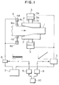
- reference numeral 1 denotes a material whose width is to be worked or compressed, and in this embodiment this material has a sheet-like form.
- Reference numeral 2 denotes anvil blocks 2, which constituts press tools, for applying compressive forces (working forces) respectively to side surfaces of the material 1
- reference numeral 3 denotes compression means for reducing the width of the sheet material 1.
- Each compression means 3 includes a cylinder 3a, a piston 3b mounted in the cylinder 3a, and a piston rod 3c connected to a respective one of the anvil blocks 2.
- the anvil blocks 2 are so arranged as to hold the material 1 therebetween, and the compression means 3 are provided outwardly of the anvil blocks, respectively.
- Reference numeral 4 denotes vibration-applying means for applying vibrations directly to the side surfaces of the material 1, respectively.
- Each vibration-applying means 4 includes a roller 4a in contact with the side surface of the material 1, a piston rod 4b supporting the roller 4a, a piston 4c, and a cylinder 4d.
- the rollers 4a of the vibration-applying means 4 are provided independently of the compression means 3 at the inlet side for the material 1 in the anvil blocks 2.
- At least two sets of vibration-applying means 4 are provided at the inlet side of the anvil blocks 2 so as to hold the material 1 therebetween.
- the pistons 3b of the compression means 3 are controlled by a control valve 5, and the pistons 4c of the vibration-applying means 4 are controlled by a control valve 6.
- the control valves 5 and 6 are connected to a power unit 7 which supplies an operating fluid to the control valves 5 and 6, and receives the operating fluid discharged therefrom.
- the control valves 5 and 6 are driven respectively by control instructions fed respectively from controllers 8 and 9.
- the controllers 8 and 9 are controlled by a host controller 10.
- the compression means 3 are driven by the control valve 5 controlled by a monotonic signal.
- the vibration-applying means 4 are driven by the control valve 6 controlled by an oscillation signal.
- the vibration to be applied to the material 1 can be small in force and displacement amount, but need to have a high frequency of several kHz in order to resonate the material.
- the compressive force or the rolling load serving as the working force, and the vibration force for vibrating the material 1 which totally differ in required properties can be applied to material 1, respectively.
- a fluid pressure mechanism for the compression means or the pressing means and a fluid pressure mechanism for the vibration-applying means can be designed into respective suitable constructions independently of each other.
- the compression means 3 or the pressing means is constituted by an electrically-operated mechanism having a crankshaft mechanism
- the vibration-applying means 4 is constituted by a fluid pressure mechanism using a cylinder.
- systems most suitable for various requirements can be used in combination.
- the compression means 3 or the pressing means can be constituted by a fluid pressure mechanism
- the vibration-applying means 4 can be constituted by an electrically-operated mechanism using a crankshaft mechanism, a cam mechanism or a link mechanism.
- the compression means 3 or the pressing means and the vibration-applying means 4 are constituted by fluid pressure mechanisms, respectively, and if the compression means 3 or the pressing means requiring a large thrust and a large displacement amount uses a system in which the cylinder, having a large bore and a large stroke, is controlled by the control valve having high pressure and a high flow rate while the vibration-applying means 4 requiring a high frequency uses a system in which the cylinder, having a small stroke, is controlled by the high-response control valve, the following operation is effected:
- the natural frequency f n of the fluid pressure mechanism which vibrates the load with a mass M by the cylinder having a pressure-receiving area A is expressed by formula 1 if the sum of the volume of the operating fluid in the cylinder and the volume of the operating fluid in a pipe extending from the control valve to the cylinder is represented by V, and the bulk modulus of the operating fluid is represented by K.
- f n 1 2 ⁇ 4A 2 K vM
- the pressure-receiving area A is large since the compression means or the pressing means requires a large thrust, and therefore the required flow rate is high, and in order to reduce a pressure loss, the diameter of the pipe is large, so that the volume in the pipe extending from the control valve and the cylinder is large.
- the stroke is large in order to obtain a large displacement amount, the volume in the cylinder is large.
- the sum V of the volume of the operating fluid in the cylinder and the volume of the operating fluid in the pipe extending from the control valve to the cylinder is large, and the mass M is large. Therefore, the natural frequency f n of the fluid pressure mechanism is small.
- the vibration-applying means 4 are provided independently, the thrust and stroke can be small, and therefore the mass M is small, and the sum V of the volume of the operating fluid in the cylinder and the volume of the operating fluid in the pipe extending from the control valve to the cylinder is small. Therefore, the natural frequency f n of the fluid pressure mechanism can be increased. Therefore, there can be achieved the vibration-applying means capable of vibrating the material at an extremely high frequency corresponding to the resonance frequency of the material.
- the vibration-applying means 4 are provided separately from the compression means 3 or the pressing means, and the material is vibrated not through press tools and working rolls having a large mass, then the mass of the moving parts of the vibration-applying means 4 can be made smaller. Therefore, the natural frequency can be made higher, and the limit value of the frequency of the applied vibration is further enhanced, so that the vibration can be effected at a higher frequency.
- the required thrust in the vibration-applying means of the width-compressing apparatus using the anvil blocks is 1/10 of the thrust required in the means for effecting both compression and vibration in the conventional technique, and the stroke is 1/50, then the pressure-receiving area A is 1/10, and the sum V of the volume of the operating fluid in the cylinder and the volume of the operating fluid in the pipe is 1/500.
- the natural frequency f n of the fluid pressure mechanism is about twelve times higher.
- the diameter of the pipe is decreased, and the volume in the pipe extending from the control valve to the cylinder is decreased, and therefore the sum V of the volume of the operating fluid in the cylinder and the volume of the operating fluid in the pipe is further decreased, so that the natural frequency f n of the fluid pressure mechanism becomes higher. Therefore, the natural frequency f n of the fluid pressure mechanism can be made higher several tens of times or more, and the limit vibration frequency is greatly increased.
- the resonance frequency f W in the direction of the width of the sheet is expressed by formula 2.
- the resonance frequency f W of a material (which has a sheet width of 1200 mm, and is to be hot processed) in the direction of the width of the sheet is about 1.6 kHz. Therefore, if the limit vibration frequency which has heretofore been up to about 100 Hz at best is increased as described above, the material can be resonated.
- the ratio of the strain ⁇ C at the central portion of the sheet to the strain ⁇ E at the sheet side edge portion is expressed by formula 5, and varies relative to the ratio of the frequency f of the applied vibration to the resonance frequency f W as shown in Fig. 2. Namely, as the frequency f of the applied vibration becomes closer to the resonance frequency f W in the direction of the width of the sheet, the dynamic strain at the central portion of the sheet becomes larger as compared with the strain at the sheet side edge portion. The larger the dynamic strain is, the more easily the deformation goes beyond the elastic range when the compressive force is applied from the compression means, so that plastic deformation is liable to occur.
- a dog bone phenomenon D in which the sheet thickness after the width compression is larger at the sheet side edge portions than at the central portion of the sheet as shown in Fig. 3 is less liable to occur
- a width return phenomenon E in which the thickened side edge portion of the sheet is caused to flow outwardly to increase the sheet width during rolling by the rolling mill A at a later stage, is also less liable to occur. Therefore, the working precision after the rolling is enhanced, is also less.
- an improper shape such as a fish-tail F developing at leading and trailing ends of the material, is less liable to occur, so that a crop loss is reduced, and the yield is increased.
- the compression means 3 or the pressing means and the vibration-applying means 4 may use different operating fluids, respectively, and therefore if the vibration-applying means 4 uses the operating fluid greater in the bulk modulus K than the operating fluid for the compression means or the pressing means, the limit frequency of the vibration produced by the vibration-applying means 4 can be further increased.
- a surge pressure ⁇ p abruptly produced, for example, upon striking of the material against the press tools and the working rolls, can be reduced because the surge pressure ⁇ p, expressed by formula 6, increases with the increase of K, so that the surge pressure ⁇ p can be reduced if the compression means or the pressing means use the operating fluid having a small value of k.
- ⁇ p ⁇ k ⁇ ⁇ ⁇ v
- the material 1 can be vibrated at a higher frequency, and can be vibrated at an extremely high frequency close to the resonance frequency of the material. Therefore, the effect of promoting the plastic deformation by the vibration is enhanced, so that the material can be plastically deformed more uniformly.
- the compression amount or the pressing amount increases, and the force and energy required for the working can be reduced, and the widthwise-compressing machine and the rolling mill can be reduced in size, and the working precision can be enhanced.
- the natural frequency f n of the fluid pressure mechanism is represented by the above formula 1, and the cylinder will not respond at a frequency above this natural frequency, so that the displacement amount decreases.
- the compression means 3 has the large pressure-receiving area A and the large stroke, so that the volume of the cylinder is large.
- the diameter of the pipe is large so as to reduce the pressure loss, and the sum V of the volume of the operating fluid in the cylinder and the volume of the operating fluid in the pipe from the control valve to the cylinder is extremely large.
- the anvil blocks as press tools which are rigid and have a large mass, the mass M is large. Therefore, in the compression means 3, the natural frequency f n of the fluid pressure mechanism is low, and the material 1 can not be vibrated at such a high frequency as to resonate the material 1.
- the vibration-applying means 4 are provided independently of the compression means 3, and further vibrations are applied not through the anvil blocks 2, and therefore the bore and stroke of the cylinder 4d of the vibration-applying means 4 can be reduced, and the sum V of the volume of the operating fluid in the cylinder and the volume of the operating fluid in the pipe from the control valve to the cylinder, as well as the mass M, can be reduced, so that the natural frequency f n of the fluid pressure mechanism can be increased.
- the material 1 can be vibrated at such an extremely high frequency that the material can be resonated. This promotes the plastic deformation, so that the sheet material 1 is deformed uniformly up to the central portion thereof.
- Characteristics indicated in a broken line in Fig. 4 are obtained when compressing the material without applying vibrations thereto, whereas characteristics indicated in a solid line are obtained when compressing the material while vibrating the same at a high frequency.
- the compressive force required for achieving the same compression amount is smaller as compared with the case of compressing the material without vibrations. Therefore, there can be realized the width-compressing machine in which the compression amount can be increased, and the force and energy required for the working can be reduced, and the size of the machine can be smaller than the conventional machine. And, the working precision of the sheet width is enhanced. Particularly, the material is deformed uniformly up to the central portion thereof without causing the dog bone phenomenon, in which the deformation concentrates on those portions of the material near to the anvil blocks, thus thickening these portions, so that the sheet thickness after the width compression is uniform.
- the width return phenomenon is less liable to occur at a later rolling step, and the precision of the sheet width after the rolling operation is enhanced, and further the leading and trailing end portions of the processed material having an undesirable shape such as a fish-tail shape are shortened. Therefore, the yield is improved.
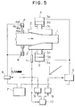
- Fig. 5 shows another embodiment of an apparatus of the invention.
- the same reference numerals in Figs. 1 and 5 denote identical or corresponding parts, respectively. This is the same with the other Figures showing the following embodiments of the invention.
- the amount of compression of a material 1 is detected by a displacement sensor 11 provided on one of anvil blocks 2, and is fed back to a host controller 10.
- the host controller 10 controls a controller 9 of vibration-applying means and pistons 4c of the vibration-applying means 4 so that the frequency of the vibration can increase.
- the resonance frequency increases with the decrease of the sheet width of the material 1.
- the frequency of the applied vibration can be varied in accordance with the change of the resonance frequency due to the change of the sheet width, so that the material is always kept in a proper condition and preferably in a resonant condition during the widthwise-compressing operation. Therefore, the effects, such as the increase of the compression amount, the reduction of the force and energy required for the working, and the improved working precision, can be further enhanced.
- Fig. 6 shows a further embodiment of an apparatus of the invention in which rollers 4a of vibration-applying means 4 are provided downstream of anvil blocks 2 in a direction of supply of a material 1.
- rollers 4a of vibration-applying means 4 are provided downstream of anvil blocks 2 in a direction of supply of a material 1.
- Fig. 7 shows yet another embodiment of an apparatus of the invention in which two pairs of vibration-applying means 4 are provided upstream and downstream of anvil blocks 2, respectively.
- Fig. 7 shows yet another embodiment of an apparatus of the invention in which two pairs of vibration-applying means 4 are provided upstream and downstream of anvil blocks 2, respectively.
- Fig. 8 shows a still further embodiment of an apparatus of the invention in which cylinders 4d of vibration-applying means 4 are fixedly mounted on downstream-side ends of anvil blocks 2, respectively.
- cylinders 4d of vibration-applying means 4 are fixedly mounted on downstream-side ends of anvil blocks 2, respectively.
- Fig. 9 shows an additional embodiment of the invention in which each of vibration-applying means 4 is incorporated or built in a piston 3b and a piston rod 3c of a respective one of compression means 3.
- each of vibration-applying means 4 is incorporated or built in a piston 3b and a piston rod 3c of a respective one of compression means 3.
- Fig. 10 shows another embodiment of an apparatus of the invention in which one anvil block 2 is movable while the other anvil block 2 is fixed, and compression means 3 is connected to the movable anvil block 2, and vibration-applying means 4 is mounted on the fixed anvil block 2.
- compression means 3 is connected to the movable anvil block 2
- vibration-applying means 4 is mounted on the fixed anvil block 2.
- Fig. 11 shows a further embodiment of an apparatus of the invention in which a power unit 12 for compression means 3 and a power unit 13 for vibration-applying means 4 are provided separately from each other, and the compression means 3 and the vibration-applying means 4 are incorporated respectively in two fluid pressure circuits independent of each other. Different operating fluids are used in the two independent fluid pressure circuits, and with this arrangement the following effects are achieved.
- the operating fluid for the vibration-applying means 4 is larger in K, i.e. the bulk modulus, than the operating fluid for the compression means 3, the natural frequency f n , representing the limit vibration frequency of the vibration-applying means 4, can be further increased.
- a surge pressure ⁇ p abruptly produced upon striking of the press tools 2 against the material 1, is expressed by the above formula 2, and the larger the value of K is, the higher this surge pressure is. Therefore, if the operating fluid having a small value of K is used for the compression means 3, the surge pressure ⁇ p, abruptly produced upon striking of the press tools 2 against the material 1, can be reduced, so that the lifetime of the apparatus can be prolonged.
- the vibration-applying means in all of the above embodiments are of such a construction that the operating fluid, supplied from the power unit to the cylinder and discharged from the cylinder to the power unit, is controlled by the control valve, thereby controlling the movement of the anvil block or blocks.
- a vibration fluid pressure-generating source such as a kind of pump which alternately effects the suction and discharge of the operating fluid by mechanical movement achieved by a rotating drive source such as an electric motor.
- the control valve or the vibration fluid pressure-generating source may be connected to each of cylinders 4d of the vibration-applying means 4, or may be connected to one of the cylinders 4d.
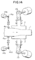
- Fig. 12 shows yet another embodiment of an apparatus of the invention in which a mechanism for driving each of rollers 4a, disposed so as to hold a material 1 therebetween, of vibration-applying means 4 comprises a support member 4e supporting the roller 4a, guide means 4f for guiding the support member 4e, a crankshaft mechanism 14a, and a drive motor 14b for driving the crankshaft mechanism 14.
- a mechanism for driving each of rollers 4a, disposed so as to hold a material 1 therebetween, of vibration-applying means 4 comprises a support member 4e supporting the roller 4a, guide means 4f for guiding the support member 4e, a crankshaft mechanism 14a, and a drive motor 14b for driving the crankshaft mechanism 14.
- Fig. 13 shows a still further embodiment of an apparatus of the invention in which each of a pair of compression means 3 comprises a crankshaft mechanism 15.
- the vibration-applying means and the compression means may comprise crankshaft mechanisms 14 and 15, respectively, as shown in Fig. 14, and may comprise any other suitable mechanisms.
- the limit vibration frequency of the vibration-applying means can be increased. Therefore, the plastic deformation is further promoted, effects, such as the increase of the compression amount, the reduction of the force and energy required for the working, the compact design of the apparatus, and the improvement of the working precision, can be obtained as in the above embodiments.
- Vibration-applying means 16 may be so provided as to vibrate the material in a direction of travel of the material, as shown in Fig. 15. With this arrangement, widthwise components of the vibration forces act on the material through opposed slanting side surfaces of two anvil blocks 2, and therefore similar effects as describe in the above embodiments are achieved.
- the vibration force may be applied to the material through the anvil blocks as in this embodiment.
- the resonance frequency is relative low, and therefore even if the material is vibrated together with the anvil blocks 2, similar effects due to the plastic deformation as described above are achieved.
- Vibration-applying means 17 may be so provided as to vibrate the material in a direction of the thickness of the material, as shown in Fig. 16. With this arrangement, vibrations propagate in the material in various directions, thus producing widthwise components of the vibration forces, and therefore similar effects as described above are achieved.
- the vibration-applying means are provided respectively on the upper and lower sides of the material, and anvil blocks 2 are held respectively against lateral side edges or surfaces of the material 1, and compression means 3 are disposed outwardly of the anvil blocks 2, respectively.
- FIG. 17 Another preferred embodiment of a widthwise-compressing machine of the invention is shown in Fig. 17.
- press tools for compressing the width of a material 1 comprises rotary rolls 31, and the rotary rolls 31 are so arranged as to hold the material 1 therebetween.
- the other portions are the same as described in the embodiment of Fig. 3. More specifically, in this width-compressing machine, the pair of rotary rollers 31 are rotated by respective rotation drive devices 33 while applying forces, produced by cylinders 32 constituting compression means through the rotary rolls 31 to the material 1 in the direction of the width of the material.
- cylinders 34 which serve as vibration-applying means, for applying vibrations to the material 1 not through the rotary rolls 31.
- the cylinders 32 are controlled by a control valve 35, and the cylinders 34 are controlled by a control valve 36.
- a power unit 37 which supplies an operating fluid to the control valves 35 and 36, and receives the operating fluid therefrom.
- the control valves 35 and 36 are controlled respectively by control instructions fed respectively from controllers 38 and 39.
- the controllers 38 and 39 are controlled by a host controller 40.
- a monotonic signal is fed to the cylinders 32 serving as compression means, and an oscillation signal is fed to the cylinders 34 serving as vibration-applying means.
- the vibration-applying means are provided independently of the compression means as in the above embodiments using the anvil blocks, and the material can be vibrated at such a high frequency that the material can be resonated. Therefore, plastic deformation of the material is promoted by the applied vibrations, and the increase of the compression amount, the reduction of the force and energy required for the working, the compact design of the apparatus, and the improvement of the working precision can be enhanced.
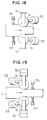
- the rotary rolls 31 may be fixedly mounted on support bases 41, respectively, and the compression of the material is effected utilizing reaction forces from the support bases 41.
- This construction is the same as that of Fig. 17 in that rotation drive devices 33 are connected to the rotary rolls 31, respectively.
- the cylinders 34 of the vibration-applying means may be provided downstream of the rotary rolls 31 of the compression means as shown in Fig. 19. Also, in addition to the cylinders 34 provided upstream of the rotary rolls 31, another pair of cylinders 34' as vibration-applying means 34' may be provided downstream of the rotary rolls 31, as shown in Fig. 20.
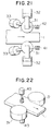
- Cylinders 42 of vibration-applying means may be so provided as to vibrate the material in the direction of travel of the material, as shown in Fig. 21. Also, cylinders 43 of vibration-applying means may be so provided as to vibrate the material in the direction of the thickness of the material, as shown in Fig. 22.
- the rolling mill 51 includes a cylinder 55 as pressing means which applies a rolling load, which forms a main working force, to a material 54 through a pair of upper and lower auxiliary rolls 53 and a pair of upper and lower working rolls 52.
- a power unit 56 supplies an operating fluid to the cylinder 55 of the pressing means, and receives the operating fluid from the cylinder 55.
- a control valve 57 controls the flow of this operating fluid, and a controller 58 feeds a control instruction to the control valve 57.
- Cylinders 59 as vibration-applying means for applying vibrations to the material 54 are provided at an upstream side of the rolling mill 51.
- a control valve 60 controls the flow of the operating fluid supplied to and discharged from the cylinders 59.
- a controller 61 feeds a control instruction to the control valve 60.
- a displacement amount sensor 62 is provided on the cylinder 55 of the pressing means, and an output signal from this sensor is fed back to the controller 58 so as to position the cylinder 55, thereby controlling a gap between the upper and lower working rolls 52 for holding the sheet-like material 54.
- the pair of cylinders 55 of the pressing means, as well as the pair of control valves 57, the pair of controllers 58 and the pair of displacement amount sensors 62, are provided at the operation side and drive side of the rolling mill 51, respectively.
- the two controllers 58 for the pressing means provided respectively at the operation side and the drive side, as well as the controller 61 for the vibration-applying means, are controlled by a host controller 63 so that the material 54 can be rolled to be reduced into a desired thickness, thus providing a rolled product.
- the vibration-applying means are provided independently of the pressing means as in the above embodiments of the width-compressing machines, so that the material can be vibrated at a high frequency. Since the thickness of the sheet-like material is smaller than the width thereof, the resonance frequency of the material is very high in the direction of the sheet thickness. However, by the use of the vibration-applying means of this embodiment, the material can be vibrated at a frequency closer to the resonance frequency than in the conventional construction, thereby enabling the effect of promoting plastic deformation to be enhanced. Therefore, the increase of the pressing amount, the reduction of the rolling load and energy, the compact design of the apparatus and the precision of the sheet thickness can be enhanced.
- the diameter of working rolls need to be small in order to increase the pressing amount, so that there has been encountered a problem that the working rolls are liable to deflection in a horizontal direction, thus lowering the performance.
- an increased pressing amount can be obtained even with the use of the working rolls larger in diameter than the working rolls of the conventional apparatus. This advantageously overcomes the lowering of the quality due to deflection of the working rolls.
- the cylinders 59 of the vibration-applying means may be provided at the downstream side of the rolling mill 51. Also, in addition to the cylinders 59 provided at the upstream side of the rolling mill 51, another pair of cylinders may be provided at the downstream side. With such constructions, similar effects as described above are achieved.
- a slab 102a continuously produced by a continuous casting machine 101, is treated by a heating/heat-retaining device 103 into a condition suited for hot plastic working, and then is fed to a widthwise-compressing machine 104 where the slab 102 is reduced in width into a slab 102b smaller in width than the slab 102a. Then, the slab 102b is greatly reduced in thickness by coarse rolling mills 105, and then is rolled by finish rolling mills 106 into a final thickness to provide a strip 102c.
- the widthwise-compressing machine 104 has the same construction as that shown in Fig. 3, and includes vibration-applying means 110 for applying vibrations to the material or slab, the vibration-applying means 110 being provided at an upstream side independently of compression means for applying a main working force to the material.
- the plastic deformation of the slab is promoted by the vibrations applied by the vibration-applying means 110, so that the slab is deformed uniformly up to the widthwise central portion of the slab. Therefore, a dog bone phenomenon is less liable to occur, and width return and fish tail are less liable to occur upon rolling, and therefore the precision and quality of the rolled product, as well as the yield, are enhanced.
- the widthwise-compressing machine 104 can achieve a large amount of compression, the time required for compressing the material to the desired width can be shortened, and the overall production ability of the rolling equipment is enhanced. And besides, the range of adjustment of the sheet width by the widthwise-compressing machine 104 is wide, and therefore the frequency of exchange of casting dies of the continuous casting machine 101 can be reduced, and the operating efficiency of the equipment can be enhanced. Furthermore, the width-compressing machine 104 requires small energy for working the material, and therefore the running cost can be reduced. Since the width-compressing machine 102 is of a small or compact size, the overall length of the equipment can be reduced, and the installation cost can be reduced.
- steps of a production process i.e. a contiguous casting step, a heating/heat-retaining step, width-compressing step, a coarse rolling step, a finish rolling step, a cooling step, a cutting step and a winding step
- the rolling facilities of this embodiment differs from the preceding embodiment in that a width-compressing machine comprises an edger in which the sheet width is adjusted or reduced by rotary rolls, that vibration-applying means 151 are provided at an upstream side of the width-compressing machine, and that vibration-applying means 152 are provided between a pair of coarse rolling machines 105.
- the plastic deformation of the material is promoted in the edger 150, and therefore similar effects as described in the embodiment of Fig. 24 are achieved.
- the plastic deformation of the material in the coarse rolling mills 105 are promoted, so that the amount of reduction or pressing of the material by coarse rolling can be increased, and the precision is enhanced. Therefore, not only the reduction of the rolling load and energy and the compact design of the coarse rolling mills can be achieved, but also the number of finish rolling mills 106 can be reduced. Therefore, advantageously, the overall length of the production equipment can be reduced, and the installation cost can be reduced.
- vibration-applying means may be provided on the finish rolling mills. With this construction, greater effects can be achieved.
- the material can be vibrated at a higher frequency, and therefore it is possible to vibrate the material at an extremely high frequency close to the resonance frequency of the material, so that the plastic deformation of the material is further promoted, and the material is deformed uniformly up to the widthwise central portion thereof.
- the widthwise-compressing machine, as well as the rolling mill can be of a smaller size than the conventional machines, and the space for installing the production equipment, as well as the installation cost, can be reduced.
- great effects can be obtained from technical and economical points of view.
Landscapes
- Engineering & Computer Science (AREA)
- Mechanical Engineering (AREA)
- Metal Rolling (AREA)
- Press Drives And Press Lines (AREA)
- Forging (AREA)
- Casting Or Compression Moulding Of Plastics Or The Like (AREA)
Applications Claiming Priority (3)
| Application Number | Priority Date | Filing Date | Title |
|---|---|---|---|
| JP06219820A JP3092460B2 (ja) | 1994-09-14 | 1994-09-14 | 幅圧縮加工機及び圧延機 |
| JP219820/94 | 1994-09-14 | ||
| JP21982094 | 1994-09-14 |
Publications (3)
| Publication Number | Publication Date |
|---|---|
| EP0703013A2 true EP0703013A2 (fr) | 1996-03-27 |
| EP0703013A3 EP0703013A3 (fr) | 1996-08-07 |
| EP0703013B1 EP0703013B1 (fr) | 1999-07-14 |
Family
ID=16741555
Family Applications (1)
| Application Number | Title | Priority Date | Filing Date |
|---|---|---|---|
| EP95114339A Expired - Lifetime EP0703013B1 (fr) | 1994-09-14 | 1995-09-12 | Machine pour presser transversalement et laminoir équipé de cette machine |
Country Status (8)
| Country | Link |
|---|---|
| US (1) | US5699693A (fr) |
| EP (1) | EP0703013B1 (fr) |
| JP (1) | JP3092460B2 (fr) |
| KR (1) | KR100219749B1 (fr) |
| CN (1) | CN1067920C (fr) |
| BR (1) | BR9504015A (fr) |
| DE (1) | DE69510739T2 (fr) |
| TW (1) | TW339288B (fr) |
Cited By (3)
| Publication number | Priority date | Publication date | Assignee | Title |
|---|---|---|---|---|
| EP0968774A4 (fr) * | 1997-11-26 | 2003-06-11 | Ishikawajima Harima Heavy Ind | Installation et procede pour la fabrication de bandes d'acier laminees a chaud |
| CN100528387C (zh) * | 1997-11-26 | 2009-08-19 | 石川岛播磨重工业株式会社 | 热轧带钢的生产方法 |
| KR101330899B1 (ko) | 2008-07-31 | 2013-11-22 | 나가토시 오카베 | 피가공물의 확경 가공 방법 |
Families Citing this family (20)
| Publication number | Priority date | Publication date | Assignee | Title |
|---|---|---|---|---|
| US6722174B1 (en) * | 1999-03-10 | 2004-04-20 | Nkk Corporation | Device and method for manufacturing hot-rolled sheet steel and device and method for sheet thickness pressing used for the device and method |
| KR100327794B1 (ko) * | 1999-11-26 | 2002-03-15 | 정명식 | 금속판 압연 시스템 |
| US6543136B1 (en) | 2000-06-29 | 2003-04-08 | Siemens Automotive Corporation | Method for improved valve seating of a fuel injector by coining and a valve made thereby |
| DE10113645A1 (de) * | 2001-03-21 | 2002-10-02 | Siempelkamp Pressen Sys Gmbh | Umformeinheit |
| US8479552B1 (en) * | 2007-05-22 | 2013-07-09 | Temper Ip, Llc | Method and die for forming a tubular blank into a structural component |
| DE102009007926A1 (de) * | 2009-02-06 | 2010-08-19 | Benteler Automobiltechnik Gmbh | Verfahren zur Herstellung von umfangsseitig konturierten länglichen Formplatinen aus einem Metallstreifen |
| JP5691777B2 (ja) | 2011-04-14 | 2015-04-01 | 株式会社Ihi | 粉末圧延装置及び粉末圧延方法 |
| JP2012251217A (ja) * | 2011-06-03 | 2012-12-20 | Ihi Corp | 粉末圧延装置 |
| KR101287622B1 (ko) * | 2011-11-28 | 2013-07-23 | 한국생산기술연구원 | 초음파 압출장치 |
| US9174263B2 (en) | 2012-05-23 | 2015-11-03 | Temper Ip, Llc | Tool and shell using induction heating |
| US9656317B1 (en) | 2014-02-03 | 2017-05-23 | Temper Ip, Llc | Stamp, mold, quench of aluminum and magnesium sheet |
| JP6813416B2 (ja) * | 2017-04-10 | 2021-01-13 | 株式会社日立製作所 | プラント制御装置およびその制御方法、圧延機制御装置およびその制御方法並びにプログラム |
| DE102017110882B4 (de) * | 2017-05-18 | 2019-10-31 | Siempelkamp Maschinen- Und Anlagenbau Gmbh | Presse |
| DE102018212899A1 (de) * | 2018-08-02 | 2020-02-06 | Bayerische Motoren Werke Aktiengesellschaft | Verfahren zum Herstellen eines Kraftfahrzeugbauteils |
| CN109794507B (zh) * | 2019-01-18 | 2020-05-26 | 西京学院 | 一种高性能铝合金板材横向振动轧制工艺 |
| KR102448748B1 (ko) * | 2020-11-16 | 2022-09-30 | 주식회사 포스코 | 빌렛 형상교정방법 및 형상교정장치 |
| CN113245492B (zh) * | 2021-05-19 | 2023-07-04 | 中国第二重型机械集团德阳万航模锻有限责任公司 | 大型整体框锻造模具的制备方法及挤压扩孔方法 |
| CN115488156B (zh) * | 2021-06-18 | 2024-10-29 | 上海宝信软件股份有限公司 | 冷轧机液压压下位置控制系统震荡检测与保护方法及系统 |
| CN113787095B (zh) * | 2021-09-03 | 2024-05-03 | 太原理工大学 | 一种可施加水平振动的金属复合板轧制装置 |
| CN116713322B (zh) * | 2023-08-01 | 2026-02-06 | 扬州恒润海洋重工有限公司 | 一种用于热连轧的精轧机组 |
Family Cites Families (18)
| Publication number | Priority date | Publication date | Assignee | Title |
|---|---|---|---|---|
| US2767767A (en) * | 1952-06-06 | 1956-10-23 | Longren Aircraft Company | Method and apparatus for straightening integrally reinforced metal extrusions |
| DE1147909B (de) * | 1957-07-10 | 1963-05-02 | Zentralinstitut Fuer Automatis | Werkzeug zum Umformen von Blech |
| US3333452A (en) * | 1965-03-03 | 1967-08-01 | Sendzimir Inc T | Reduction of thick flat articles |
| US3534574A (en) * | 1968-03-14 | 1970-10-20 | Univ Ohio | Process for the hot forming of metal |
| SU570421A2 (ru) * | 1975-11-17 | 1977-08-30 | Донецкий Ордена Трудового Красного Знамени Политехнический Институт | Способ регулировани поперечной разнотолщинности полосы |
| SU686794A1 (ru) * | 1976-06-17 | 1979-09-25 | Донецкий Ордена Трудового Красного Знамени Политехнический Институт | Устройство дл регулировани поперечной разнотолщинности полосы |
| SU615957A1 (ru) * | 1977-01-04 | 1978-06-19 | Донецкий Ордена Трудового Красного Знамени Политехнический Институт | Способ вибрационной прокатки |
| SU617089A1 (ru) * | 1977-01-04 | 1978-07-04 | Донецкий Ордена Трудового Красного Знамени Политехнический Институт | Способ вибрационной прокатки |
| AT363894B (de) * | 1977-02-14 | 1981-09-10 | Langenecker Bertwin Dr | Verfahren und vorrichtung zum walzen von blechen, stangen, draehten u.dgl. mittels makroschall |
| SU789166A1 (ru) * | 1978-12-08 | 1980-12-23 | за вители | Устройство дл ультразвуковой прокатки материалов |
| DE3376530D1 (en) * | 1982-12-01 | 1988-06-16 | Hitachi Ltd | Press apparatus for reducing slab width |
| US4651550A (en) * | 1983-11-28 | 1987-03-24 | Hitachi, Ltd. | Method of decreasing width of thin slab and apparatus therefor |
| JPS60121001A (ja) * | 1983-12-02 | 1985-06-28 | Hitachi Ltd | 幅圧延装置 |
| JPS61222651A (ja) * | 1985-03-27 | 1986-10-03 | Ishikawajima Harima Heavy Ind Co Ltd | 鍛造プレス装置 |
| JPS61262401A (ja) * | 1985-05-17 | 1986-11-20 | Hitachi Ltd | 板材料の幅圧縮加工方法 |
| JPH02147109A (ja) * | 1988-11-30 | 1990-06-06 | Hitachi Ltd | プレス式スラブ幅減少装置 |
| US5046344A (en) * | 1990-01-19 | 1991-09-10 | United Engineering, Inc. | Apparatus for sizing a workpiece |
| JP3189919B2 (ja) * | 1993-03-05 | 2001-07-16 | 石川島播磨重工業株式会社 | 幅圧下プレス装置 |
-
1994
- 1994-09-14 JP JP06219820A patent/JP3092460B2/ja not_active Expired - Fee Related
-
1995
- 1995-09-11 TW TW084109465A patent/TW339288B/zh active
- 1995-09-12 DE DE69510739T patent/DE69510739T2/de not_active Expired - Fee Related
- 1995-09-12 KR KR1019950029625A patent/KR100219749B1/ko not_active Expired - Fee Related
- 1995-09-12 US US08/527,182 patent/US5699693A/en not_active Expired - Fee Related
- 1995-09-12 EP EP95114339A patent/EP0703013B1/fr not_active Expired - Lifetime
- 1995-09-13 BR BR9504015A patent/BR9504015A/pt not_active IP Right Cessation
- 1995-09-14 CN CN95116300A patent/CN1067920C/zh not_active Expired - Fee Related
Non-Patent Citations (1)
| Title |
|---|
| None |
Cited By (3)
| Publication number | Priority date | Publication date | Assignee | Title |
|---|---|---|---|---|
| EP0968774A4 (fr) * | 1997-11-26 | 2003-06-11 | Ishikawajima Harima Heavy Ind | Installation et procede pour la fabrication de bandes d'acier laminees a chaud |
| CN100528387C (zh) * | 1997-11-26 | 2009-08-19 | 石川岛播磨重工业株式会社 | 热轧带钢的生产方法 |
| KR101330899B1 (ko) | 2008-07-31 | 2013-11-22 | 나가토시 오카베 | 피가공물의 확경 가공 방법 |
Also Published As
| Publication number | Publication date |
|---|---|
| CN1067920C (zh) | 2001-07-04 |
| DE69510739D1 (de) | 1999-08-19 |
| KR100219749B1 (ko) | 1999-09-01 |
| BR9504015A (pt) | 1996-09-24 |
| CN1119560A (zh) | 1996-04-03 |
| JP3092460B2 (ja) | 2000-09-25 |
| DE69510739T2 (de) | 2000-01-13 |
| JPH0890010A (ja) | 1996-04-09 |
| TW339288B (en) | 1998-09-01 |
| KR960010101A (ko) | 1996-04-20 |
| EP0703013A3 (fr) | 1996-08-07 |
| EP0703013B1 (fr) | 1999-07-14 |
| US5699693A (en) | 1997-12-23 |
Similar Documents
| Publication | Publication Date | Title |
|---|---|---|
| US5699693A (en) | Widthwise compressing machine and method using vibrations to reduce material width | |
| US6463652B1 (en) | Apparatus and methods for manufacturing hot rolled steel sheets | |
| EP0112516B1 (fr) | Dispositif pour réduire la largeur de brame | |
| EP2058059B1 (fr) | Procédés et appareil pour la commande de machines de conditionnement de matériaux | |
| KR20010080063A (ko) | 압연기 | |
| US3921429A (en) | Process and apparatus for modifying the cross section of a slab | |
| WO1997027953A1 (fr) | Interruption du flottement des rouleaux d'un laminoir par vibrations induites | |
| CN112453404B (zh) | 用于金属粉末半固态初轧带材的精轧系统 | |
| US6742440B2 (en) | Servo-controlled integral stop for use with a servo-controlled hydraulic piston | |
| US20100162784A1 (en) | Flattening device | |
| JPH0824922B2 (ja) | プレス式スラブ幅減少方法、及びその装置 | |
| KR100616209B1 (ko) | 판 두께 압축장치의 금형 간극 조절장치 | |
| KR100740485B1 (ko) | 웨브 또는 시트 재료를 가공하는 방법 및 이 방법을 사용하는 프레스 | |
| JPH05269511A (ja) | ワークロールクロス圧延機のワークロールチョック位置安定装置 | |
| SU686794A1 (ru) | Устройство дл регулировани поперечной разнотолщинности полосы | |
| JPH08117803A (ja) | 圧延方法及び圧延機並びにタンデムミル | |
| KR920009966B1 (ko) | 진동하중에 의한 엘보의 제조장치 및 그 제조방법 | |
| GB1593318A (en) | Manufacture of roled products | |
| JP2538855B2 (ja) | スラブ材の縮幅方法及び装置 | |
| CN223186011U (zh) | 一种精密冷弯成型机 | |
| JP4162331B2 (ja) | スラブ成形方法及び装置 | |
| JPS62187535A (ja) | スラブ用サイジングプレス | |
| DE69838151T2 (de) | Plattenpressvorrichtung und Verfahren | |
| JPH0641990U (ja) | 金属板の連続プレス加工装置 | |
| JPS60187409A (ja) | 圧延機 |
Legal Events
| Date | Code | Title | Description |
|---|---|---|---|
| PUAI | Public reference made under article 153(3) epc to a published international application that has entered the european phase |
Free format text: ORIGINAL CODE: 0009012 |
|
| AK | Designated contracting states |
Kind code of ref document: A2 Designated state(s): DE FR GB |
|
| PUAL | Search report despatched |
Free format text: ORIGINAL CODE: 0009013 |
|
| AK | Designated contracting states |
Kind code of ref document: A3 Designated state(s): DE FR GB |
|
| 17P | Request for examination filed |
Effective date: 19960628 |
|
| 17Q | First examination report despatched |
Effective date: 19970530 |
|
| GRAG | Despatch of communication of intention to grant |
Free format text: ORIGINAL CODE: EPIDOS AGRA |
|
| GRAG | Despatch of communication of intention to grant |
Free format text: ORIGINAL CODE: EPIDOS AGRA |
|
| GRAH | Despatch of communication of intention to grant a patent |
Free format text: ORIGINAL CODE: EPIDOS IGRA |
|
| GRAH | Despatch of communication of intention to grant a patent |
Free format text: ORIGINAL CODE: EPIDOS IGRA |
|
| GRAA | (expected) grant |
Free format text: ORIGINAL CODE: 0009210 |
|
| AK | Designated contracting states |
Kind code of ref document: B1 Designated state(s): DE FR GB |
|
| REF | Corresponds to: |
Ref document number: 69510739 Country of ref document: DE Date of ref document: 19990819 |
|
| ET | Fr: translation filed | ||
| PLBE | No opposition filed within time limit |
Free format text: ORIGINAL CODE: 0009261 |
|
| STAA | Information on the status of an ep patent application or granted ep patent |
Free format text: STATUS: NO OPPOSITION FILED WITHIN TIME LIMIT |
|
| 26N | No opposition filed | ||
| REG | Reference to a national code |
Ref country code: GB Ref legal event code: IF02 |
|
| PGFP | Annual fee paid to national office [announced via postgrant information from national office to epo] |
Ref country code: FR Payment date: 20020716 Year of fee payment: 8 |
|
| PGFP | Annual fee paid to national office [announced via postgrant information from national office to epo] |
Ref country code: GB Payment date: 20020902 Year of fee payment: 8 |
|
| PGFP | Annual fee paid to national office [announced via postgrant information from national office to epo] |
Ref country code: DE Payment date: 20021129 Year of fee payment: 8 |
|
| PG25 | Lapsed in a contracting state [announced via postgrant information from national office to epo] |
Ref country code: GB Free format text: LAPSE BECAUSE OF NON-PAYMENT OF DUE FEES Effective date: 20030912 |
|
| PG25 | Lapsed in a contracting state [announced via postgrant information from national office to epo] |
Ref country code: DE Free format text: LAPSE BECAUSE OF NON-PAYMENT OF DUE FEES Effective date: 20040401 |
|
| GBPC | Gb: european patent ceased through non-payment of renewal fee |
Effective date: 20030912 |
|
| PG25 | Lapsed in a contracting state [announced via postgrant information from national office to epo] |
Ref country code: FR Free format text: LAPSE BECAUSE OF NON-PAYMENT OF DUE FEES Effective date: 20040528 |
|
| REG | Reference to a national code |
Ref country code: FR Ref legal event code: ST |