EP0703427B1 - Panneau créé par gonflage et procédé pour la fabrication par gonflage de panneaux - Google Patents
Panneau créé par gonflage et procédé pour la fabrication par gonflage de panneaux Download PDFInfo
- Publication number
- EP0703427B1 EP0703427B1 EP94114865A EP94114865A EP0703427B1 EP 0703427 B1 EP0703427 B1 EP 0703427B1 EP 94114865 A EP94114865 A EP 94114865A EP 94114865 A EP94114865 A EP 94114865A EP 0703427 B1 EP0703427 B1 EP 0703427B1
- Authority
- EP
- European Patent Office
- Prior art keywords
- shunt
- passageway
- width
- passage
- curved
- Prior art date
- Legal status (The legal status is an assumption and is not a legal conclusion. Google has not performed a legal analysis and makes no representation as to the accuracy of the status listed.)
- Expired - Lifetime
Links
Images

Classifications
-
- B—PERFORMING OPERATIONS; TRANSPORTING
- B21—MECHANICAL METAL-WORKING WITHOUT ESSENTIALLY REMOVING MATERIAL; PUNCHING METAL
- B21D—WORKING OR PROCESSING OF SHEET METAL OR METAL TUBES, RODS OR PROFILES WITHOUT ESSENTIALLY REMOVING MATERIAL; PUNCHING METAL
- B21D53/00—Making other particular articles
- B21D53/02—Making other particular articles heat exchangers or parts thereof, e.g. radiators, condensers fins, headers
- B21D53/04—Making other particular articles heat exchangers or parts thereof, e.g. radiators, condensers fins, headers of sheet metal
- B21D53/045—Making other particular articles heat exchangers or parts thereof, e.g. radiators, condensers fins, headers of sheet metal by inflating partially united plates
-
- F—MECHANICAL ENGINEERING; LIGHTING; HEATING; WEAPONS; BLASTING
- F25—REFRIGERATION OR COOLING; COMBINED HEATING AND REFRIGERATION SYSTEMS; HEAT PUMP SYSTEMS; MANUFACTURE OR STORAGE OF ICE; LIQUEFACTION SOLIDIFICATION OF GASES
- F25B—REFRIGERATION MACHINES, PLANTS OR SYSTEMS; COMBINED HEATING AND REFRIGERATION SYSTEMS; HEAT PUMP SYSTEMS
- F25B39/00—Evaporators; Condensers
- F25B39/02—Evaporators
- F25B39/022—Evaporators with plate-like or laminated elements
- F25B39/024—Evaporators with plate-like or laminated elements with elements constructed in the shape of a hollow panel
-
- F—MECHANICAL ENGINEERING; LIGHTING; HEATING; WEAPONS; BLASTING
- F28—HEAT EXCHANGE IN GENERAL
- F28F—DETAILS OF HEAT-EXCHANGE AND HEAT-TRANSFER APPARATUS, OF GENERAL APPLICATION
- F28F3/00—Plate-like or laminated elements; Assemblies of plate-like or laminated elements
- F28F3/12—Elements constructed in the shape of a hollow panel, e.g. with channels
- F28F3/14—Elements constructed in the shape of a hollow panel, e.g. with channels by separating portions of a pair of joined sheets to form channels, e.g. by inflation
Definitions
- the pair of roll-bonded plates is arranged between two first and second platen of a suitable press. Thereafter the outer ring shaped fluid circuit is inflated so that a pressure tight seal for the volume between the platen of the press is provided. Then the airtight volume on one side of the panel is pressurized and thereupon the inner fluid circuit pattern is inflated by air pressure supplied via a passageway serving as a delay line for inflating pressure.
- the present process is very effective in the case where a U-shaped passage or V-shaped passage is formed by a portion of the first shunt passageway proximate to the curved passageway, the curved passageway and a portion of the second shunt passageway proximate to the curved passageway.
- air having a pressure not lower than 80 kg/cm 2 to not higher than 130 kg/cm 2 is introduced into the nonbonded portions for inflation.
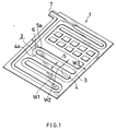
- FIG. 1 shows a roll-bonded panel obtained by the production process of the invention.
- the roll-bonded panel 1 is produced by printing a pattern corresponding to a fluid circuit on one surface of one of a pair of upper and lower aluminum plates with a parting agent (bonding preventing agent), roll-bonding the aluminum plates with the other aluminum plate superposed on the printed surface, and thereafter inflating nonbonded portions to a tubular form with air of high pressure introduced into these portions.
- This embodiment has an inflated tube on one side thereof over the entire area.
- the upper aluminum plate only is inflated, and the lower aluminum plate is flat.
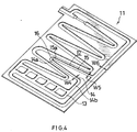
- the second embodiment differs from the first with respect to the following.
- the first and second shunt passageways 14, 15 are not parallel to each other.
- a V-shaped passage is formed by the portion of the first passageway 14 proximate to the curved passageway 16, the curved passageway 16 and the portion of the second passageway 15 proximate to the curved portion 16.
- the first shunt passageway 14 is not straight and is held in communication with the main passage 13 by a straight passageway 14b connected to the passageway 14 approximately perpendicular thereto.
Landscapes
- Engineering & Computer Science (AREA)
- Mechanical Engineering (AREA)
- Physics & Mathematics (AREA)
- Thermal Sciences (AREA)
- General Engineering & Computer Science (AREA)
- Air Bags (AREA)
- Blow-Moulding Or Thermoforming Of Plastics Or The Like (AREA)
- Lining Or Joining Of Plastics Or The Like (AREA)
- Pressure Welding/Diffusion-Bonding (AREA)
- Laminated Bodies (AREA)
Claims (6)
- Procédé pour fabriquer un panneau laminé (1, 11) présentant un circuit de fluide, en gravant un dessin correspondant au circuit de fluide sur une surface d'une première plaque d'aluminium à l'aide d'un agent de séparation, en laminant ladite plaque d'aluminium avec une seconde plaque d'aluminium posée sur la surface gravée, puis en dilatant les parties non assemblées pour définir une forme tubulaire à l'aide d'une pression de fluide, caractérisé en ce que le circuit de fluide comprend un passage principal (3, 13) et au moins un passage de dérivation (2, 12) moins large que celui-ci, et le passage de dérivation (2, 12) comprend un premier passage de dérivation (4, 14) partant d'une partie du passage principal (3, 13), un second passage de dérivation (5, 15) partant d'une autre partie du passage principal (3, 13), et un passage courbe (6, 16) défini entre les deux passages de dérivation (4, 5) et (14, 15), étant précisé que la largeur (W2, W5) d'une première partie non assemblée à transformer en premier passage de dérivation (5, 15 ; 4, 14) est inférieure à la largeur (W1, W4) de la seconde partie non assemblée à transformer en second passage de dérivation (4, 14 ; 5, 15), et que la partie non assemblée à transformer en passage courbe (6, 16) a une largeur croissante de la première partie non assemblée à transformer en premier passage de dérivation (5, 15 ; 4, 14) vers la seconde partie non assemblée à transformer en second passage de dérivation (4, 14 ; 5, 15), et étant précisé que lors de la formation du passage de dérivation par dilatation, le passage de dérivation le plus large est formé en premier, puis le passage courbe, et enfin le passage de dérivation le moins large.
- Procédé de fabrication selon la revendication 1, caractérisé en ce que la différence entre la largeur (W1, W4) de la partie non assemblée à transformer en premier passage de dérivation (4, 14) et la largeur (W2, W5) de la partie non assemblée à transformer en second passage de dérivation (5, 15) n'est pas inférieure à 0,2 mm.
- Procédé de fabrication selon la revendication 1 ou 2, caractérisé en ce qu'un passage en U est défini par une partie (4a) du premier passage de dérivation (4) située près du passage courbe (6), par ledit passage courbe (6) et par une partie (5a) du second passage de dérivation (5) située près du passage courbe (6).
- Procédé de fabrication selon la revendication 1 ou 2, caractérisé en ce qu'un passage en V est défini par une partie (14a) du premier passage de dérivation (14) située près du passage courbe (16), par ledit passage courbe (16) et par une partie (15a) du second passage de dérivation (15) située près du passage courbe (16).
- Procédé de fabrication selon l'une quelconque des revendications 1 à 4, caractérisé en ce que de l'air présentant une pression de 80 kg/cm2 minimum et de 130 kg/cm2 maximum est introduit dans les parties non assemblées, en vue de la dilatation.
- Panneau laminé (1, 11) formé à partir de deux plaques d'aluminium grâce à la gravure d'un dessin de circuit de fluide sur une surface d'une première plaque d'aluminium à l'aide d'un agent de séparation, au laminage des plaques d'aluminium, la seconde plaque étant posée sur la surface gravée, puis à la dilatation des parties non assemblées pour définir une forme tubulaire à l'aide d'une pression de fluide, caractérisé en ce que le circuit de fluide comprend un passage principal (3, 13) et au moins un passage de dérivation (2, 12) moins large que celui-ci, et le passage de dérivation (2, 12) comprend un premier passage de dérivation (4, 14) partant d'une partie du passage principal (3, 13), un second passage de dérivation (5, 15) partant d'une autre partie du passage principal (3, 13), et un passage courbe (6, 16) défini entre les deux passages de dérivation (4, 5) et (14, 15), étant précisé que la largeur d'une partie non assemblée à transformer en second passage de dérivation est inférieure à la largeur de l'autre partie non assemblée à transformer en premier passage de dérivation, et que le passage courbe a une largeur croissante.
Priority Applications (3)
| Application Number | Priority Date | Filing Date | Title |
|---|---|---|---|
| AT94114865T ATE182673T1 (de) | 1994-09-21 | 1994-09-21 | Durch aufblähen hergestellte platte und verfahren zur herstellung von platten durch aufblähung |
| EP94114865A EP0703427B1 (fr) | 1994-09-21 | 1994-09-21 | Panneau créé par gonflage et procédé pour la fabrication par gonflage de panneaux |
| DE69419754T DE69419754T2 (de) | 1994-09-21 | 1994-09-21 | Durch Aufblähen hergestellte Platte und Verfahren zur Herstellung von Platten durch Aufblähung |
Applications Claiming Priority (1)
| Application Number | Priority Date | Filing Date | Title |
|---|---|---|---|
| EP94114865A EP0703427B1 (fr) | 1994-09-21 | 1994-09-21 | Panneau créé par gonflage et procédé pour la fabrication par gonflage de panneaux |
Publications (2)
| Publication Number | Publication Date |
|---|---|
| EP0703427A1 EP0703427A1 (fr) | 1996-03-27 |
| EP0703427B1 true EP0703427B1 (fr) | 1999-07-28 |
Family
ID=8216303
Family Applications (1)
| Application Number | Title | Priority Date | Filing Date |
|---|---|---|---|
| EP94114865A Expired - Lifetime EP0703427B1 (fr) | 1994-09-21 | 1994-09-21 | Panneau créé par gonflage et procédé pour la fabrication par gonflage de panneaux |
Country Status (3)
| Country | Link |
|---|---|
| EP (1) | EP0703427B1 (fr) |
| AT (1) | ATE182673T1 (fr) |
| DE (1) | DE69419754T2 (fr) |
Families Citing this family (7)
| Publication number | Priority date | Publication date | Assignee | Title |
|---|---|---|---|---|
| FR2817954B1 (fr) | 2000-12-11 | 2003-01-10 | Pechiney Rhenalu | Procede de fabrication de panneaux en aluminium a circuit integre |
| DE50111025D1 (de) * | 2001-01-08 | 2006-10-26 | Flamm Ag | Verfahren zum herstellen von verdampferplatten |
| FR2867843B1 (fr) * | 2004-03-22 | 2006-04-28 | Pechiney Rhenalu | Panneau de refroidissement pour refrigerateur ou congelateur |
| BRPI0602254A (pt) * | 2006-05-26 | 2008-01-22 | Univ Minas Gerais | placa aletada para trocador de calor, a partir de chapas metálicas, unidas em fase sólida por colaminação ou por outros processos de compressão |
| CN102889635B (zh) * | 2012-10-26 | 2016-08-24 | 唐玉敏 | 一种整体成型无焊缝暖气片及其生产方法 |
| CN103033014B (zh) * | 2012-12-27 | 2015-08-26 | 合肥美的电冰箱有限公司 | 制冷设备 |
| CN108231932A (zh) * | 2018-03-14 | 2018-06-29 | 中南大学 | 一种太阳能光伏光热组件制造工艺 |
Family Cites Families (4)
| Publication number | Priority date | Publication date | Assignee | Title |
|---|---|---|---|---|
| US2874942A (en) * | 1954-08-25 | 1959-02-24 | Metal Specialty Company | Means for joining pressure-welded tubes |
| US3334398A (en) * | 1964-11-02 | 1967-08-08 | Olin Mathieson | Fabrication of hollow articles |
| FR2561368B1 (fr) * | 1983-12-01 | 1986-08-14 | Cegedur | Procede de fabrication de panneaux monoface a circuit integre pour echangeurs de chaleur |
| JPH0195826A (ja) * | 1987-10-06 | 1989-04-13 | Showa Alum Corp | ロールボンドパネル製造用合せ板 |
-
1994
- 1994-09-21 AT AT94114865T patent/ATE182673T1/de not_active IP Right Cessation
- 1994-09-21 DE DE69419754T patent/DE69419754T2/de not_active Expired - Fee Related
- 1994-09-21 EP EP94114865A patent/EP0703427B1/fr not_active Expired - Lifetime
Also Published As
| Publication number | Publication date |
|---|---|
| ATE182673T1 (de) | 1999-08-15 |
| EP0703427A1 (fr) | 1996-03-27 |
| DE69419754T2 (de) | 2000-02-10 |
| DE69419754D1 (de) | 1999-09-02 |
Similar Documents
| Publication | Publication Date | Title |
|---|---|---|
| EP0358523B1 (fr) | Structures en forme de coupole et procédé pour les réaliser par moulage superplastique et soudage par diffusion | |
| EP1013355B1 (fr) | Structure de cordons de soudure avec réserve d'angle pour un ensemble de tôles empilées devant subir une déformation superplastique | |
| US5685075A (en) | Method for brazing flat tubes of laminated heat exchanger | |
| US4331284A (en) | Method of making diffusion bonded and superplastically formed structures | |
| US5881459A (en) | Pressure communication for superplastically formed, diffusion bonded panels and method of manufacture | |
| EP0703427B1 (fr) | Panneau créé par gonflage et procédé pour la fabrication par gonflage de panneaux | |
| US5505256A (en) | Heat exchangers and methods of manufacture thereof | |
| US5070607A (en) | Heat exchange and methods of manufacture thereof | |
| US20070200391A1 (en) | Method for the Production of a Vehicle Component, Particularly a Chassis Frame | |
| JPH04227481A (ja) | 熱交換器要素とその製作法 | |
| JP2837206B2 (ja) | 超塑性成形/拡散接合サンドウィッチ湾曲構造体 | |
| US5385204A (en) | Heat exchanger and methods of manufacture thereof | |
| EP0414435B1 (fr) | Méthode de fabrication d'un échangeur de chaleur | |
| EP1406793B1 (fr) | Structure de cable d'attache pour airbag | |
| US20060103168A1 (en) | Preform for hydroforming hydroforming method, and hydroformed product | |
| US4577797A (en) | Apparatus and method for making laminate structures | |
| WO1995031682A1 (fr) | Echangeur thermique a plaques soudees et procede pour souder les plaques de transfert thermique sur un echangeur thermique a plaques | |
| EP0894552B1 (fr) | Améliorations relatives à la fabrication des échangeurs de chaleur | |
| US5392625A (en) | Method of making non-planar article from roll bonded metal sheets | |
| GB2129340A (en) | Stiffened panel | |
| EP0206416A2 (fr) | Unité d'échange de chaleur à plaques et méthode de fabrication | |
| JPH0442102B2 (fr) | ||
| EP0117710A2 (fr) | Dispositif de tubes obtenu par placage par laminage de feuillard couvert de métal d'apport de brasage fort | |
| US3354530A (en) | Method for preparing expanded pressure passageway products | |
| JP2689996B2 (ja) | 蒸発器 |
Legal Events
| Date | Code | Title | Description |
|---|---|---|---|
| PUAI | Public reference made under article 153(3) epc to a published international application that has entered the european phase |
Free format text: ORIGINAL CODE: 0009012 |
|
| AK | Designated contracting states |
Kind code of ref document: A1 Designated state(s): AT CH DE ES FR GB IT LI SE |
|
| 17P | Request for examination filed |
Effective date: 19960605 |
|
| 17Q | First examination report despatched |
Effective date: 19971111 |
|
| GRAG | Despatch of communication of intention to grant |
Free format text: ORIGINAL CODE: EPIDOS AGRA |
|
| GRAG | Despatch of communication of intention to grant |
Free format text: ORIGINAL CODE: EPIDOS AGRA |
|
| GRAH | Despatch of communication of intention to grant a patent |
Free format text: ORIGINAL CODE: EPIDOS IGRA |
|
| GRAH | Despatch of communication of intention to grant a patent |
Free format text: ORIGINAL CODE: EPIDOS IGRA |
|
| GRAA | (expected) grant |
Free format text: ORIGINAL CODE: 0009210 |
|
| AK | Designated contracting states |
Kind code of ref document: B1 Designated state(s): AT CH DE ES FR GB IT LI SE |
|
| PG25 | Lapsed in a contracting state [announced via postgrant information from national office to epo] |
Ref country code: SE Free format text: THE PATENT HAS BEEN ANNULLED BY A DECISION OF A NATIONAL AUTHORITY Effective date: 19990728 Ref country code: LI Free format text: LAPSE BECAUSE OF FAILURE TO SUBMIT A TRANSLATION OF THE DESCRIPTION OR TO PAY THE FEE WITHIN THE PRESCRIBED TIME-LIMIT Effective date: 19990728 Ref country code: ES Free format text: THE PATENT HAS BEEN ANNULLED BY A DECISION OF A NATIONAL AUTHORITY Effective date: 19990728 Ref country code: CH Free format text: LAPSE BECAUSE OF FAILURE TO SUBMIT A TRANSLATION OF THE DESCRIPTION OR TO PAY THE FEE WITHIN THE PRESCRIBED TIME-LIMIT Effective date: 19990728 Ref country code: AT Free format text: LAPSE BECAUSE OF FAILURE TO SUBMIT A TRANSLATION OF THE DESCRIPTION OR TO PAY THE FEE WITHIN THE PRESCRIBED TIME-LIMIT Effective date: 19990728 |
|
| REF | Corresponds to: |
Ref document number: 182673 Country of ref document: AT Date of ref document: 19990815 Kind code of ref document: T |
|
| REG | Reference to a national code |
Ref country code: CH Ref legal event code: EP |
|
| REF | Corresponds to: |
Ref document number: 69419754 Country of ref document: DE Date of ref document: 19990902 |
|
| ITF | It: translation for a ep patent filed | ||
| ET | Fr: translation filed | ||
| PG25 | Lapsed in a contracting state [announced via postgrant information from national office to epo] |
Ref country code: GB Free format text: LAPSE BECAUSE OF NON-PAYMENT OF DUE FEES Effective date: 19991028 |
|
| REG | Reference to a national code |
Ref country code: CH Ref legal event code: PL |
|
| PLBE | No opposition filed within time limit |
Free format text: ORIGINAL CODE: 0009261 |
|
| STAA | Information on the status of an ep patent application or granted ep patent |
Free format text: STATUS: NO OPPOSITION FILED WITHIN TIME LIMIT |
|
| GBPC | Gb: european patent ceased through non-payment of renewal fee |
Effective date: 19991028 |
|
| 26N | No opposition filed | ||
| REG | Reference to a national code |
Ref country code: FR Ref legal event code: TP |
|
| PGFP | Annual fee paid to national office [announced via postgrant information from national office to epo] |
Ref country code: FR Payment date: 20060908 Year of fee payment: 13 |
|
| PGFP | Annual fee paid to national office [announced via postgrant information from national office to epo] |
Ref country code: DE Payment date: 20060914 Year of fee payment: 13 |
|
| PGFP | Annual fee paid to national office [announced via postgrant information from national office to epo] |
Ref country code: IT Payment date: 20060930 Year of fee payment: 13 |
|
| PG25 | Lapsed in a contracting state [announced via postgrant information from national office to epo] |
Ref country code: DE Free format text: LAPSE BECAUSE OF NON-PAYMENT OF DUE FEES Effective date: 20080401 |
|
| REG | Reference to a national code |
Ref country code: FR Ref legal event code: ST Effective date: 20080531 |
|
| PG25 | Lapsed in a contracting state [announced via postgrant information from national office to epo] |
Ref country code: FR Free format text: LAPSE BECAUSE OF NON-PAYMENT OF DUE FEES Effective date: 20071001 |
|
| PG25 | Lapsed in a contracting state [announced via postgrant information from national office to epo] |
Ref country code: IT Free format text: LAPSE BECAUSE OF NON-PAYMENT OF DUE FEES Effective date: 20070921 |