EP0704293A2 - Procédé de régulation en température d'unités d'injection et de moules d'injection de matières plastiques - Google Patents
Procédé de régulation en température d'unités d'injection et de moules d'injection de matières plastiques Download PDFInfo
- Publication number
- EP0704293A2 EP0704293A2 EP95114774A EP95114774A EP0704293A2 EP 0704293 A2 EP0704293 A2 EP 0704293A2 EP 95114774 A EP95114774 A EP 95114774A EP 95114774 A EP95114774 A EP 95114774A EP 0704293 A2 EP0704293 A2 EP 0704293A2
- Authority
- EP
- European Patent Office
- Prior art keywords
- temperature
- cycle
- temperature control
- time
- tool
- Prior art date
- Legal status (The legal status is an assumption and is not a legal conclusion. Google has not performed a legal analysis and makes no representation as to the accuracy of the status listed.)
- Granted
Links
Images
Classifications
-
- B—PERFORMING OPERATIONS; TRANSPORTING
- B29—WORKING OF PLASTICS; WORKING OF SUBSTANCES IN A PLASTIC STATE IN GENERAL
- B29C—SHAPING OR JOINING OF PLASTICS; SHAPING OF MATERIAL IN A PLASTIC STATE, NOT OTHERWISE PROVIDED FOR; AFTER-TREATMENT OF THE SHAPED PRODUCTS, e.g. REPAIRING
- B29C45/00—Injection moulding, i.e. forcing the required volume of moulding material through a nozzle into a closed mould; Apparatus therefor
- B29C45/17—Component parts, details or accessories; Auxiliary operations
- B29C45/76—Measuring, controlling or regulating
- B29C45/78—Measuring, controlling or regulating of temperature
-
- B—PERFORMING OPERATIONS; TRANSPORTING
- B29—WORKING OF PLASTICS; WORKING OF SUBSTANCES IN A PLASTIC STATE IN GENERAL
- B29C—SHAPING OR JOINING OF PLASTICS; SHAPING OF MATERIAL IN A PLASTIC STATE, NOT OTHERWISE PROVIDED FOR; AFTER-TREATMENT OF THE SHAPED PRODUCTS, e.g. REPAIRING
- B29C45/00—Injection moulding, i.e. forcing the required volume of moulding material through a nozzle into a closed mould; Apparatus therefor
- B29C45/17—Component parts, details or accessories; Auxiliary operations
- B29C45/76—Measuring, controlling or regulating
- B29C45/7666—Measuring, controlling or regulating of power or energy, e.g. integral function of force
Definitions
- the invention relates to a method for temperature control of injection molding machine units, in particular for the processing of crosslinkable polymers, and molding tool units for plastics processing, with at least one temperature control circuit.
- the thermal operating state of the mold with the mold temperature as a measure along with the cylinder and melt temperature is one of the most important thermal function variables. It has a great influence on the flowability of the plastic melt, the cycle time and the quality of the molded parts, in particular the surface quality, the shrinkage and the warpage.
- the thermal operating state of the plasticizing cylinder is of crucial importance for the processing of crosslinkable high polymers.
- the thermal operating state of the plasticizing cylinder is of crucial importance for the processing of crosslinking high polymers. Such materials require a relatively low temperature level during the dwell time in the plasticizing cylinder during processing into molded parts in order to prevent premature crosslinking or partial crosslinking of the molding composition.
- the amount of heat generated during plasticization through friction of the mass, ie through the conversion of mechanical energy, is usually greater in the stationary, ie retracted, machine state than the amount of heat necessary to achieve an optimal mass viscosity.
- the temperature control of the molding compound or melt in the screw / cylinder system must be controlled so that no premature crosslinking reactions occur as a result of excessively high melt temperatures.
- the exact temperature control for the molding compound via the cylinder temperature control has a significant influence on the quality of the molded parts to be produced. In practice, only the way of working with temperature control units has prevailed so far, but they have some fundamental disadvantages, which will be described in detail below in the description of the use of temperature control units for injection molding tools are also mentioned.
- a method is known in which the cooling phase is interrupted after the injection process, followed by an annealing phase and followed by a renewed cooling phase, which should continue until the residual energy content of the molded part is sufficient around the injection mold to a temperature favorable for the subsequent injection molding cycle.
- the disadvantage of this method is that technologically-related differences in the heat dissipation of the individual cooling phases at the beginning of the manufacturing process must be adjusted manually by varying the throttling of the cooling water flow at the control valves or by varying the setting of adjustable time relays, the duration of the cooling phases. This requires a considerable amount of work and places increased demands on the operating personnel.
- EP 0 218 919 B1 discloses a method for calibrating and correcting the device for mold temperature control in injection molding machines, in which a computer closes and opens the valves as a function of a temperature difference in the molds after a measurement period with the valves open to the maximum and a measurement period controls with closed valves. After reaching the target temperatures, two calibration cycles are carried out, in which the distance behavior of the tool is tested by the measured temperature drop or rise. On the basis of the determined temperature differences, the computer calculates the opening times of the valves, which are necessary to maintain the specified target temperature.
- the temperature control is only based on the currently measured tool temperature.
- the hottest zone of the tool necessarily leads to the set temperature being exceeded during every injection process, even when starting up, and thus to triggering the cooling. If the thermal compensation between the melt and the tool, and between the cooling medium and the tool, as well as between the cooling medium and the tool, there is always an inertia, the temperature control as a function of the currently measured temperature can lead to a time shift in the tool temperature control and thus to tool temperatures that are significantly below or above the selected control temperature lie. Both disturbance variables in the injection molding process, for example a reduced supply of coolant, and the unfavorable position of cooling surfaces in relation to the tool contour complicated tools are not always sufficiently compensated for by these methods, so it is not always possible to adapt the temperature control conditions to the current process parameters.
- Another known temperature control method controls the temperature medium flow after calculating an average tool temperature or average return temperature of the temperature control medium or after a trend determination of the average tool temperatures or the average return temperature of several past cycles.
- the average tool temperature is compared with a specified target temperature and the cooling regime is changed in the subsequent cycle if the average tool temperature deviates from the specified target temperature.
- the measurement location for the temperature measurement in the tool or in the return of the temperature control medium is not considered critical, but this is in contradiction to the knowledge gained in practice. In the procedure described above, only general statements are made regarding the opening time of the solenoid valves in the cycle.
- the solenoid valve is opened if the average temperature of the previous cycle is above an upper limit temperature, and on the other hand if the average temperatures of a number of previous cycles signal a rising trend near the set temperature.
- the opening time itself should depend on the "rate" of the temperature change or the size of the difference to the accepted temperature range.
- a concrete, comprehensible calculation rule is not dealt with in any more detail.
- the control of the mold temperature in the subsequent cycle practiced with this method does not take acutely occurring disturbances in the cycle into account. These disturbances are corrected retrospectively and via the relatively slow mechanism of an average temperature. It can be assumed that the control described in general, and in the case of active disturbances, in particular "runs behind" the actual tool temperature, the intended high process stability not being achieved.
- the flow temperature is not measured, which means that a significant influencing factor of the thermal operating state of the tool is not taken into account and, in the event of changes, inevitably leads to deviations from the target thermal state of the tool. Furthermore, experience shows that the deviations of an average return temperature from a predetermined setpoint temperature, particularly in the case of larger volume flows, which occur in the run-in machine in the event of a malfunction, are so small that a meaningful influence on the flow time of the temperature control medium is not always possible.
- the invention was based on the object of a method for temperature control of injection molding machine units, in particular for the processing of crosslinkable polymers, and molding tool units for plastics processing, with at least one temperature control circuit, the return temperature of the temperature control medium or the cylinder or tool temperature being measured and as a result of an actual Should the comparison of the flow rate of the temperature control medium be changed, to ensure that, taking into account the current parameters of the injection molding process, including any disruptions in the process, it ensures a sufficiently precise constancy of the thermal operating state of the tool with self-adjusting control and works without additional energy.
- the heat content in the tool or plasticizing cylinder is determined by heat-supplying components (heat quantity of the injected melt, hot runner temperature control, ...) and heat-dissipating components (tool or plasticizing cylinder cooling, heat dissipation by convection and radiation, heat conduction). If the thermal operating state of the tool or plasticizing cylinder is to be kept constant during injection molding, the inevitable fluctuations in the individual components in the manufacturing process, which determine the heat content, must affect the thermal operating state, for example the Tool to be compensated.
- the tool cooling or temperature control can be specifically controlled, in particular there is a need to control the duration of the temperature medium flow in the tool in such a way that faults of all kinds, which affect the heat content of the tool, such as changes in the temperature of the melt, fluctuations in the temperature and volume of the temperature control medium, changes in the cycle time, fluctuations in the ambient temperature, etc. are compensated for.
- the following basic explanations refer to the variants of measuring the tool temperature or the cylinder temperature.
- the temperature control process is divided into two phases, a start-up phase and a stationary operating phase, each with different temperature control conditions.
- the tempering impulses per cycle are always at time Z 1, which is determined by a signal from the machine sequence control, in close proximity to the injection process during mold temperature control or in close proximity to the plasticizing process, the start of screw rotation, at Tempering of plasticizing cylinders initiated in order to bring about the necessary heat dissipation in the time range of the greatest temperature difference between the injected melt and the tempering channel.
- time Z1 is determined by a signal from the machine sequence control, in close proximity to the injection process during mold temperature control or in close proximity to the plasticizing process, the start of screw rotation, at Tempering of plasticizing cylinders initiated in order to bring about the necessary heat dissipation in the time range of the greatest temperature difference between the injected melt and the tempering channel.
- the mean tool temperature is continuously reduced for the respective Temperature control circuit, measured thermally by both the injected melt and the temperature applied to an equivalent temperature, this location being approximately in the area of the geometric center between the contour of the mold and the cooling channel or surface and in the area between the cooling water inlet and outlet at a sufficiently large distance to the contour of the shape, or in the case of cylinder temperature control in the area of the geometric center between the cylinder inner wall and the temperature control channel.
- a so-called reference cycle is selected in accordance with a predetermined mode to be described, which ends the start-up phase.
- the heat content in this reference cycle is usually used as a setpoint for the heat content in all subsequent cycles.
- WRG (u1, u2) (the size relevant to the heat content) according to (1) is introduced.
- WRG (u 1 , u 2nd ) U 1 U 2nd T (t)
- German WRG (u1, u2) is defined and calculated analogously to the integral of the temperature curve T (t) over the time axis between the times u1 and u2, u1 and u2 denoting the interval limits of the time interval.
- WRG (Z1, t D ) is calculated for the selected reference cycle, where t D means the tempering time calculated for the reference cycle.
- each subsequent cycle is divided into smallest time intervals (t i - 1, t i ) starting from the time Z 1 to the end of the tempering period t D , the temperature is measured at each time t i and the value WRG is (t i- 1, t i ) calculated according to (1).
- German WRG ist (t i - 1 , t i ) becomes permanent for every point in time t i and until the temperature control period t D has elapsed with the value WRG ref (t i - 1 , t i ) of the reference cycle and always at the same cyclical time in accordance with ( 2) compared.
- WD (t i ) WRG is (t i - 1 , t i ) - WRG ref (t i - 1 , t i )
- the difference between the two values WD (t i ) signals a difference in the amount of heat dissipated from the tool in this time interval (t i - 1 , t i ) and is used according to the method for correcting the tempering time t D by the correction time t corr (t i ) im current cycle.
- the start-up phase takes place in the first cycle, starting at time Z 1, an initial pulse t init with a fixed duration in order to achieve a first complete flushing of the temperature control circuit in question, and when a defined distance of the average tool temperature from the predetermined target temperature is reached in the following cycle at time Z 1 a tempering pulse t ann of a shorter duration is initiated, the tempering pulse t ann being initiated in all subsequent cycles until the specified target temperature is exceeded for the first time and ensuring a damped approximation of the mean tool temperature to the selected target temperature.
- a variant that occurs as a special case in the start-up phase is that if a target temperature that is below the measured actual temperature is specified, constant temperature control takes place in all subsequent cycles between times Z 1 and Z 2 until the measured actual temperature falls below the predetermined target temperature for the first time . After falling below the target temperature, the start-up phase is continued with the initiation of the coolant pulse of the duration t ann at the time Z 1 of the cycle following the first undershoot and with the renewed one The set temperature has been exceeded and the later selection of the reference cycle ended.
- the tool or the plasticizing cylinder is brought to thermal equilibrium within a number of n cycles by means of a specification of a calculated temperature control agent pulse updated per cycle and a temperature control phase dependent on the current target / actual value comparison in the cycle.
- the arithmetic mean of the cooling time per cycle is determined from the total duration of the tempering agent pulses of a specified number of immediately preceding cycles, with a factor K 1, which enables a reaction to the practically unavoidable thermal disturbances to the temperature condition of the tool, evaluated and as a calculated pulse duration t E used for the initiation of the temperature control agent in the subsequent cycle at time Z 1.
- a tempering pulse of the duration t D is triggered at the time Z 1 of the reference cycle, where t D is equal to the value t E calculated in the n th cycle according to (5), and the value WRG ref (Z1, t D ) is calculated.
- the duration t D is again tempered and the temperature integral described is calculated. If the difference between the two integrals is less than a predetermined value W G , the last cycle traveled is identified as the reference cycle, the temperature profile over time is recorded in a suitable manner and the start-up phase is considered to be complete.
- the current cycle is identified as the reference cycle and the start-up phase is completed.
- an additional heater can be switched on, which minimizes the duration of the heating to the desired thermal level in the temperature control circuits relevant for the thermal operating state or in the cylinder zones important for the thermal operating state of the material to be plasticized.
- the additional heater it is switched off at a predetermined distance between the tool or cylinder temperature and the predetermined target temperature.
- the signals from the machine sequence control which are used for the times Z1 and Z2
- the time Z1 the start of the holding pressure time and as Z2 the end of the tool opening movement is selected or as the time Z1 the start of the injection process and as Z2 the end of the tool opening movement or the time Z1 and the time Z2 are determined by the same signals of the machine sequence control, in this case Z2 is identical to the signal Z1 of the following cycle.
- Z2 is identical to the signal Z1 of the following cycle.
- the start of plasticizing is determined as the time Z 1, for example, the same variants as for the tool temperature control are available for the time Z 2.
- a factor K between 0.5 and 1.5 is introduced in (3 ') given necessary damping or reinforcing effect on the calculated correction time t corr (t i ).
- t corr K * ((T back (t i ) - T in front (t i )) is - (T back (t i ) - T in front (t i )) ref ) * (t i - t i - 1 ) (T (t d ) - T in front (t d )) ref
- WD (t i )> 0 the same derivation for t corr (t i ) is obtained, the correction time t corr (t i ) being given a negative sign.
- the actual temperature control process is separated into two phases, a start-up phase and a stationary operating phase, each with different temperature control conditions, the start-up phase being ended after the selection of the reference cycle.
- Tempering pulses are always initiated at time Z 1, in close proximity to the injection process or plasticizing process, the respective start of the screw rotation, in order to bring about the required heat dissipation in the time range of the greatest temperature difference between the injected melt or plasticized mass and the temperature control channel.
- the pulse duration during the start-up phase is determined by the start-up mode, during which it is specified as a relativized temperature control period in the stationary operating phase and is continuously adapted to the requirements of the production process as a result of the correction method described above.
- every possible temperature control in the cycle is ended.
- the method according to the invention enables an additional heater to be switched on, which minimizes the duration of the heating to the desired thermal level in the temperature control circuits relevant for the thermal operating state or in the cylinder zones important for the thermal operating state of the mass to be plasticized .
- the auxiliary heater it is switched off after a predetermined increase in the return temperature after a temperature impulse of a specified duration.
- the start-up phase takes place in the first cycle, starting at time Z 1, an initial temperature control with a temperature control pulse t init with a fixed duration in order to achieve a first complete flushing of the temperature control circuit concerned.
- the predetermined relativized duration t d is divided into start-up pulses depending on the thermal level desired in the tool, the duration of which is determined from t d .
- the integral WRG (Z 1, t d ) described is calculated for the first time over this temperature curve for this cycle.
- the subsequent cycle is identified as a reference cycle, the specified, relativized duration is tempered and the temperature integral described is again calculated.
- the difference between the two integrals is less than a predetermined value W G , the last cycle traveled is recognized as a reference cycle, the temperature profile over time in the media flow and media return is recorded in a suitable manner and the start-up phase is considered to be complete.
- W G a value between 1 and 20%, preferably 10%, of the integral WRG (Z 1, t d ) calculated as a reference is specified. If the difference between the two integrals is greater than this predetermined value W G , the predetermined relativized duration is again tempered and compared with the calculated value WRG (Z 1, t d ) of the previous cycle.
- This sequence of temperature control and integral comparison is continued for each subsequent cycle until the value falls below the preset value W G and the associated identification of the current cycle as the reference cycle and completion of the start-up phase.
- the reference cycle is the subsequent cycle after reaching the thermal equilibrium of the unit to be tempered, such as the cylinder or the tool. As described in detail, this state of equilibrium is achieved by the method steps mentioned in the start-up phase. However, it is also conceivable that the thermal equilibrium state can be achieved in a different way.
- the signals from the machine sequence control which are used for the times Z1 and Z2
- the start of the holding pressure time and as Z2 the end of the tool opening movement is selected or as the time Z1 the start of the injection process and as Z2 the end of the tool opening movement or the time Z1 and the time Z2 are determined by the same signals of the machine sequence control, in this case Z2 with the signal Z1 of Subsequent cycle is identical.
- Z2 with the signal Z1 of Subsequent cycle is identical.
- the start of plasticizing is determined as the time Z 1, for example, the same variants as for the tool temperature control are available for the time Z 2.
- the process stability during injection molding is significantly increased by the temperature control process according to the invention.
- the reject rate can be reduced by approx. 30% compared to the conventional tempering method. Cycle time reductions of approx. 5% lead to a considerable increase in productivity.
- External temperature control units with heating and circulation pumps are only required if high temperature control medium temperatures are required. As a result, the specific energy consumption of the injection molding process is reduced by approx. 10%.
- Due to the temperature control based on the measurement of the flow and return temperatures there are the additional advantages that there is no need to insert thermal sensors into the cylinder wall or the injection mold. In the case of complicated injection molding tools in particular, the drilling of the holes for the thermal sensors is associated with considerable expense.
- Another advantage is, for example, that the temperature of both the cylinder and the injection molding tool can be carried out in injection molding machines using the method according to the invention. Both process sequences can thus be integrated in a common control unit, which significantly reduces the technical outlay on equipment.
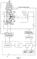
- FIG. 1 shows an injection molding machine 1 with an injection molding tool 2.
- the temperature of the injection mold 2 takes place via temperature control media circuits K 1 to K n , the flow of the temperature control medium can be interrupted or released for each tempering medium circuit by means of the solenoid valves M 1 to M n .
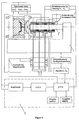
- 2 shows an injection molding machine 1 including a plasticizing cylinder 2 '.
- the temperature control of the plasticizing cylinder 2 ' takes place via temperature control circuits K 1 to K n , the flow of the temperature control medium for each temperature control circuit being able to be interrupted or released by means of the magnetic valves M 1 to M n .
- the thermal operating state of the cylinder zones which are assigned to the temperature control circuits K 1 to K n , can be raised to a predetermined temperature level by the heating circuits H 1 to H n , with exclusive use of the plasticizing waste heat, the additional heating can be dispensed with.
- the control device 3 for temperature control of the tool or plasticizing cylinder which works according to the invention, consists of the modules, adaptation stage, analog-digital converter (ADC), arithmetic unit (CPU), input unit, output unit and various interfaces.
- ADC analog-digital converter
- CPU arithmetic unit
- input unit input unit
- output unit output unit
- various interfaces various interfaces.
- a thermal sensor ThV is introduced into the temperature medium flow.
- the adaptation stage adjusts the thermal signals to the connected analog-digital converter (ADC) according to the selected sensors and transmission materials. This transmits the received thermal signals as electrical signals to a computing unit (CPU) on which they are processed.
- ADC analog-digital converter
- the software installed on the CPU determines the flow time of the temperature control medium in the respective temperature control circuit, starting from the integral over the temperature profile in a selected reference cycle, from the temperature profile measured synchronously in each subsequent cycle and the comparison integral calculated above.
- the CPU determines the start and end of the temperature control medium flow by outputting switching signals to the solenoid valve of the respective temperature control circuit. The assignability of measured values, calculation results and temperature control circuits is guaranteed.
- An input unit for entering the manipulated variables and an output unit for operator guidance are also connected to the CPU.
- the CPU initiated signals Z1 and Z2 from the sequence control of the injection molding machine provide the temporal references to the injection molding process.
- the functional circuit diagrams for the variants of temperature measurement in the injection mold or in the cylinder wall of the injection molding machine cylinder basically have the same structure, with the only difference that the thermocouples are not arranged in the media return but in the cylinder wall or in the injection mold.
- the measuring location should be arranged as far as possible in the area of the geometric center between the contour of the mold and the cooling channel or surface and in the area of the center between the temperature control medium inlet and temperature control medium output.
- Examples 1 to 3 relate to the variant for measuring the return temperature of the temperature control medium and Examples 4 to 6 relate to the variant for measuring the tool temperature or the cylinder wall temperature.
- An automotive engine ventilation part made of polyamide 6.6 is manufactured on an Krauss Maffei 150-620 B injection molding machine.
- the procedural parameters are as follows: - Tool design: 2 times - Mass of a shot (2 molded parts + sprue): 204 g - tool dimensions: 850 kg - spray pressure: 920 bar - injection time: 1.8 s - closing force: 1300 kN - Reprint: 750 bar - reprint time: 5.5 s - flow temperature: 37 ° C - cycle time: 33 s
- the injection mold is equipped with four temperature control circuits, temperature sensors in the return of each temperature control circuit and a sensor in the temperature control media supply are coupled to the control unit.
- Z1 start reprint
- Z2 the "end of the tool opening movement” is selected.
- the time between Z1 and Z2 is 22 s. 50%, ie 11 s, and 40%, ie 13.2 s, for temperature control circuits 1 and 2 (nozzle side) and temperature control circuits 3 and 4 (drive side) are specified as the relativized temperature control period t d .
- the media return temperatures of the relevant temperature control circuits are measured directly at the outlet from the tool. The temperature measurements in the return and flow are carried out continuously over the entire cycle duration.
- the difference between the two integrals (0.8) is less than a predetermined value W G (2.75), which means that the last cycle completed is recognized as the reference cycle, the temperature profile of the media flow and media return is saved and the start-up phase is considered to be complete .
- the tempering pulse of duration t d is started at time Z 1 of the respective cycle, t d (11 s) being corrected using the correction method in the course of the respective cycle and in the event of deviations in the temperature profile from the temperature profile of the so-called reference cycle.
- each subsequent cycle starting from the time Z1 to the end of the relativised tempering duration t d in the smallest time intervals (t i - 1, t i) the duration of 0.05 s subdivided, at each time t i the media return temperature measured and the value WRG is ( t i - 1 , t i ) calculated according to (1): WRG is (t i - 1 , t i ) t i - 1 T I.
- German WRG ist (t i - 1 , t i ) becomes permanent for every point in time t i and until the end of the relativized temperature control period t d with the value WRG ref (t i - 1 , t i ) of the reference cycle and always at the same cyclical time (2) compared.
- the difference WD (t i ) of the two values is used according to the method for a correction of the relativized temperature duration t d by the correction time t corr (t i ) in the current cycle.
- T back (t i ), T forward (t i ), WRG ist (t i - 1 , t i ), W D (t i ), t corr (t i ) and t d for the 50th, 80th, 120th and 200th measuring point of the 20th cycle of temperature control circuit 1 is given in the table below.
- time T back T before WRG is WD t corr t d i in t i ( o C) in t i ( o C) in t i in t i in t i (s) in t i (s) 50 41.6 37.0 0.24 -0.01 -0.04 10.1 80 40.8 37.1 0.185 -0.02 -0.04 9.4 120 39.7 37.0 0.135 0.005 0.01 9.7 200 38.1 37.0 0.06 0.01 0.02 10.6
- All temperature control circuits are supplied with process water from the company's closed cooling water network, which has a temperature of 37 o C in the flow.
- the use of a temperature control unit is not necessary.
- the molded parts mentioned in the introduction were produced in a cycle time of 33 s in accordance with quality.
- the determined reject rate was 2.6% and the specific energy consumption was 0.59 kWh / kg.
- An automobile part cover made of polypropylene filled with 40% talc is produced on an Krauss Maffei 250-1200 B injection molding machine.
- the procedural parameters are as follows: - Tool design: 1-fold - Mass of a shot (2 molded parts + sprue): 210 g - tool dimensions: 770 kg - spray pressure: 800 bar - injection time: 2.0 s - closing force: 2000 kN - Reprint: 700 bar - reprint time: 3.5 s - flow temperature: 14 o C - cycle time: 26.5 s
- the injection mold is equipped with four temperature control circuits, temperature sensors in the return of each temperature control circuit and a sensor in the temperature control media supply are coupled to the control unit.
- Z1 start reprint
- Z2 the "end of the tool opening movement” is selected.
- the time between Z1 and Z2 is 19 s. 70%, ie 5.7 s, for temperature control circuits 1 and 2 (nozzle side) and 65%, ie 6.6 s, for temperature control circuits 3 and 4 (travel side) are specified as the relativized temperature control period t d .
- the media return temperatures of the relevant temperature control circuits are measured directly at the outlet from the tool. The temperature measurements in the return and flow are carried out continuously over the entire cycle duration.
- the temperature control pulses calculated in the subsequent cycles reach a duration of between 4.2 s and 7.5 s for the circuits 1 and 2 and between 5.4 s and 8.0 s for the under the influence of practically occurring interferences on the thermal operating state of the tool Circles 3 and 4. All temperature control circuits are supplied with process water from the company's closed cooling water network, which has a temperature of approx. 14 ° C in the flow. The use of a temperature control unit is not necessary.
- the molded parts mentioned at the outset were produced over a production day in three-shift operation due to the constancy of the thermal operating state achieved with optimum process stability in a cycle time of 26.5 seconds.
- the determined reject rate was 0.85% and the specific energy consumption was 0.55 kWh / kg.
- the plasticizing cylinder is equipped with three temperature control circuits, which are coupled to the control unit via thermal sensors in the media return and a thermal sensor in the media feed. Circuit 1 (mass feed) and circuit 3 (nozzle area) are equipped with additional heaters. As the time Z1 "plasticizing start”, as Z2 the "end of the tool opening movement” is selected. The time between Z1 and Z2 is 37 s. For the temperature control circuit 1 (feed zone), 90% (3.7 s) are set as the relativized temperature control period t d , ie a relatively high level of frictional heat should be maintained; for temperature control circuits 2 (start of the discharge zone) and 3, 80% (7, 4 s).
- this specification means an increasing heat content over the cylinder in the direction of the discharge zone, which results from the frictional heat, which increases relatively strongly in this direction.
- the media return temperatures of the relevant temperature control circuits are measured directly at the outlet from the cylinder.
- the temperature measurements in the return and flow are carried out continuously over the entire cycle duration.
- a level of thermal operating state was reached after only a few minutes that the additional heaters could be switched off.
- the start-up phase is completed after 12 cycles, with 3 cycles being used to determine the reference cycle.
- the temperature control pulses calculated in the subsequent cycles reach a duration between under the influence of practically occurring interferences on the thermal operating state of the plasticizing cylinder 2.0 s and 5.5 s for circuit 1 and between 5.4 s and 8.6 s for circuits 2 and 3. All temperature control circuits are supplied with process water from the company's closed cooling water network, which has a temperature of approx. 14 o C. The use of a temperature control unit is not necessary.
- the molded parts mentioned at the outset were produced in accordance with the quality under the following parameters: - cycle time: 45 s - reject rate: 2.9% - specific energy consumption: 0.60 kWh / kg - additional Operating effort for readjustments per shift: 22 min
- An automotive engine ventilation part made of polyamide 6.6 is manufactured on an Krauss Maffei 150-620 B injection molding machine.
- the procedural parameters are as follows: - Tool design: 2 times - Mass of a shot (2 molded parts + sprue): 204 g - tool dimensions: 850 kg - spray pressure: 920 bar - injection time: 1.8 s - closing force: 1300 kN - Reprint: 750 bar - reprint time: 5.5 s - flow temperature: 37 o C - cycle time: 33 s
- the injection mold is equipped with four temperature control circuits, which are coupled to the control unit via temperature sensors.
- the tool set temperature T should be 65 o C for temperature control circuits 1 and 2 (nozzle side) and 55 o C for temperature control circuits 3 and 4 (drive side).
- the tool temperatures in the area of the relevant temperature control circuits are measured in the geometric center between the temperature control channel and the shape contour and in the possible center between the temperature medium inlet and outlet of the respective circuit.
- the temperature control circuit 1 the manner in which the sensor-receiving bore is introduced will be described.
- the hole is made between two tempering channels running parallel to each other and to the tool contour, in the geometric center between the two channels and perpendicular to the tool contour.
- the hole ends half the distance between the temperature control channel and the tool contour in front of the tool contour.
- the specific dimensions for temperature control circuit 1 are as follows: - Center distance between the two temperature control channels: 40 mm - Distance between tempering channel center and contour: 40 mm - Distance between the bottom of the hole and the contour: 20 mm.
- tempering agent pulses of limited duration are introduced into the associated cooling circuit.
- a tempering pulse t init is defined duration, with which a first complete flushing of the cooling circuit in question is achieved.
- the duration of the initial pulse t init is determined empirically from available experience values, 5 seconds being considered sufficient for this example.
- the tempering pulse of the duration t D is started at the time Z 1 of the respective cycle, with t D (12.7 s) being corrected using the correction method in the course of the respective cycle and in the event of deviations in the temperature profile from the temperature profile of the so-called reference cycle.
- each subsequent cycle is divided from the time Z 1 to the end of the calculated tempering time t D into the smallest time intervals (t i-1 , t i ) of the duration 0.05 s, the tool temperature is measured at each time t i and the value WRG is ( t i - 1 , t i ) calculated according to (1).
- WRG is (t i - 1 , t i ) t i - 1 t i T (t)
- German WRG ist (t i - 1 , t i ) becomes permanent for every point in time t i and until the temperature control period t D has elapsed with the value WRG ref (t i - 1 , t i ) of the reference cycle and always at the same cyclical time in accordance with ( 2) compared.
- the difference WD (t i ) of the two values is used according to the method for correcting the tempering time t D by the correction time t corr (t i ) in the current cycle.
- Time i T is in t i ( o C) T ref in t i WRG ref in t i t corr in t i (s) t D to t i (s) 1 64.8 64.8 3.25 0.00 12.7 50 65.8 66.3 3.30 - 0.025 12.1 80 66.7 66.7 3.34 0.00 11.8 120 66.0 66.2 3.30 -0.01 11.6 200 65.4 65.2 3.25 0.01 12.0
- the tempering impulse of 12.7 s initiated in the reference cycle, which was necessary in the reference cycle in order to maintain the predetermined target temperature, in the course of the 20th cycle from 12.7 to 12.1, 11.8 , 11.6 corrected to 12.0 s.
- All temperature control circuits are supplied with process water from the company's closed cooling water network, which has a temperature of 37 o C in the flow.
- the use of a temperature control unit is not necessary.
- the molded parts mentioned in the introduction were produced in a cycle time of 33 seconds in accordance with quality.
- the determined reject rate was 2.6% and the specific energy consumption was 0.59 kWh / kg.
- An automobile part cover made of polypropylene filled with 40% talc is produced on an Krauss Maffei 250-1200 B injection molding machine.
- the procedural parameters are as follows: - Tool design: 1-fold - Mass of a shot (2 molded parts + sprue): 210 g - tool dimensions: 770 kg - spray pressure: 800 bar - injection time: 2.0 s - closing force: 2000 kN - Reprint: 700 bar - reprint time: 3.5 s - flow temperature: 14 o C - cycle time: 26.5 s
- the injection molding tool is equipped with four temperature control circuits; thermocouples placed in the mold according to the method in the area of each temperature control circuit are coupled to the control unit.
- the time Z1 "start reprint", as Z2 the "end of the tool opening movement” is selected.
- the time between Z1 and Z2 is 19 s.
- the target temperatures are 55 o C for temperature control circuits 1 and 2 (nozzle side) and 45 o C for temperature control circuits 3 and 4 (drive side).
- the procedure is analogous to example 1, the start-up phase is completed after 8 cycles.
- the temperature control pulses calculated in the subsequent cycles reach a duration of between 4.2 s and 7.5 s for the circuits 1 and 2 and between 5.4 s and 8.0 s for the under the influence of practically occurring interferences on the thermal operating state of the tool Circles 3 and 4.
- All temperature control circuits are supplied with process water from the company's closed cooling water network, which has a temperature of approx. 14 o C in the flow. The use of a temperature control unit is not necessary.
- the molded parts mentioned at the outset were produced over a production day in three-shift operation due to the constancy of the thermal operating state achieved with optimum process stability in a cycle time of 26.5 seconds.
- the determined reject rate was 0.85% and the specific energy consumption was 0.55 kWh / kg.
- the plasticizing cylinder is equipped with three temperature control circuits which are coupled to the control unit via thermal sensors placed in the cylinder wall according to the process. Circuit 1 (mass feed) and circuit 3 (nozzle area) are equipped with additional heaters. As time Z1 is “plasticizing start”, as Z2 the “end the tool opening movement ". The time between Z1 and Z2 is 37 s.
- the target cylinder temperatures T should be for Temperature control circuit 1 (feed zone): 45 o C Temperature control circuit 2 (heating and compression zone, start of the discharge zone): 52 o C Temperature control circuit 3 (discharge zone and nozzle assembly): 60 o C given.
- the switch-on temperature for the heating is T should - 2.5 K, the switch-off temperature is T should - 2.0 K.
- the cylinder temperatures in the area of the temperature control circuits concerned are approximately in the center of gravity of the cylinder wall, i.e. with a given inner diameter of 45 mm and a given cylinder outer diameter of 90 mm, about 15 mm from the outer wall in the radial direction and the possible center between the temperature medium inlet and outlet of the respective circle measured.
- the temperature is measured continuously over the entire cycle.
- Temperierimpulse t ann of 0.3 s were taken to a subdued reaching T will cause.
- T set was selected after the 5th cycle of the first set temperature exceeding the reference cycle, thereby ending the start-up phase.
- the temperature control pulses calculated in the subsequent cycles reach a duration of between 2.0 s and 5.5 s for the circuit 1 and between 5.4 s and 8.6 s for the circuits 2 under the influence of practically occurring interferences on the thermal operating state of the plasticizing cylinder and 3.
- All temperature control circuits are supplied with process water from the company's closed cooling water network, which has a temperature of approx. 14 o C in the flow. The use of a temperature control unit is not necessary.
- the molded parts mentioned at the outset were produced in accordance with the quality under the following parameters: Cycle time: 45 s Reject rate: 2.9% specific energy consumption: 0.60 kWh / kg additional Operating effort for readjustments per shift: 22 min
- Molded parts as in Examples 1 and 4 are produced using conventional tempering under the following tempering conditions: - temperature control method: 2 double-circuit auxiliary temperature control units - temperature control medium: water - temperature control medium: 2 x 55 o C, 2 x 60 o C.
- the cycle time required was 37 seconds. In continuous operation, a reject rate of 3.1% was achieved and the specific energy consumption was 0.72 kWh / kg.
- Shaped parts as in Examples 2 and 5 are manufactured using conventional temperature control under the following temperature control conditions, the temperature of the tool being controlled using two auxiliary temperature control units: - temperature control method: 2 double-circuit auxiliary temperature control units - temperature control medium: water - temperature control medium: 2 x 50 o C (nozzle side), 2 x 45 o C (driving side).
- the cycle time required was 29 seconds. In continuous operation, a reject rate of 2.6% was achieved and the specific energy consumption was 0.69 kWh / kg.
- the procedure according to the invention achieves significantly improved process stability compared to conventional tempering.
- the main advantage is a reduction in the cycle time. According to the examples, this is about 10%. This leads to a significant increase in productivity.
- the reject rate has also been reduced considerably. In the examples, the reductions in the reject rate are 38 and 67%, respectively. Overall, this also results in a reduction in specific energy consumption, which is between 10 and 20%.
- Molded parts as in Examples 3 and 6 are produced using conventional tempering under the following tempering conditions: - temperature control method: an auxiliary temperature control unit, constant temperature control over the entire plasticizing cylinder - temperature control medium: water - temperature control medium: 75 o C
- Example 2 In continuous operation, the molded parts mentioned in Example 2 were manufactured under the following parameters: Cycle time: 52 s Reject rate: 4.2% specific energy consumption 0.70 kWh / kg additional Operating effort for readjustments per shift: 37 min.
Landscapes
- Engineering & Computer Science (AREA)
- Manufacturing & Machinery (AREA)
- Mechanical Engineering (AREA)
- Injection Moulding Of Plastics Or The Like (AREA)
- Moulds For Moulding Plastics Or The Like (AREA)
- Extrusion Moulding Of Plastics Or The Like (AREA)
- Processing Of Solid Wastes (AREA)
- Processing And Handling Of Plastics And Other Materials For Molding In General (AREA)
Applications Claiming Priority (4)
| Application Number | Priority Date | Filing Date | Title |
|---|---|---|---|
| DE4436126 | 1994-09-27 | ||
| DE19944436117 DE4436117C2 (de) | 1994-09-27 | 1994-09-27 | Verfahren zur Temperierung von Spritzgießmaschineneinheiten und Formwerkzeugeinheiten für die Kunststoffverarbeitung |
| DE4436117 | 1994-09-27 | ||
| DE19944436126 DE4436126C2 (de) | 1994-09-27 | 1994-09-27 | Verfahren zur Temperierung von Spritzgießmaschineneinheiten und Formwerkzeugeinheiten für die Kunststoffverarbeitung |
Publications (3)
| Publication Number | Publication Date |
|---|---|
| EP0704293A2 true EP0704293A2 (fr) | 1996-04-03 |
| EP0704293A3 EP0704293A3 (fr) | 1997-05-02 |
| EP0704293B1 EP0704293B1 (fr) | 2000-03-29 |
Family
ID=25940900
Family Applications (1)
| Application Number | Title | Priority Date | Filing Date |
|---|---|---|---|
| EP95114774A Expired - Lifetime EP0704293B1 (fr) | 1994-09-27 | 1995-09-20 | Procédé de régulation en température d'unités d'injection et de moules d'injection de matières plastiques |
Country Status (15)
| Country | Link |
|---|---|
| US (1) | US5720912A (fr) |
| EP (1) | EP0704293B1 (fr) |
| JP (1) | JPH08174618A (fr) |
| AT (1) | ATE191172T1 (fr) |
| BR (1) | BR9504182A (fr) |
| CA (1) | CA2159161C (fr) |
| CZ (1) | CZ289862B6 (fr) |
| DE (1) | DE59508087D1 (fr) |
| DK (1) | DK0704293T3 (fr) |
| ES (1) | ES2145860T3 (fr) |
| HU (1) | HU220271B (fr) |
| MX (1) | MX9504108A (fr) |
| PL (1) | PL178383B1 (fr) |
| PT (1) | PT704293E (fr) |
| SK (1) | SK282546B6 (fr) |
Cited By (7)
| Publication number | Priority date | Publication date | Assignee | Title |
|---|---|---|---|---|
| DE10138597B4 (de) * | 2000-11-27 | 2006-04-20 | Yudo Co. Ltd., Hwaseung | Einrichtung und Verfahren zum Steuern bzw. Regeln der Temperatur einer Spritzgussmaschine unter Verwendung einer Temperatursteuer- bzw. -regeleinrichtung |
| DE102004052499A1 (de) * | 2004-10-28 | 2006-07-13 | Faurecia Innenraum Systeme Gmbh | Spritzgusswerkzeug und Elektronikmodul |
| DE102005019890B3 (de) * | 2005-04-29 | 2006-11-30 | Dietmar Hofmann | Vorrichtung und Verfahren zur Temperierung von Formwerkzeugen |
| WO2006131278A1 (fr) * | 2005-06-10 | 2006-12-14 | Priamus System Technologies Ag | Procede de regulation du processus de moulage par injection d'une machine de moulage par injection |
| DE102012100327A1 (de) * | 2012-01-16 | 2013-07-18 | Mitras Composites Systems GmbH | Verfahren zur Aufheizung und Regelung der Temperatur eines mit einem flüssigen oder dampfförmigen Wärmeträger beheizten Werkzeuges |
| DE102017115384A1 (de) | 2017-07-10 | 2019-01-10 | HAHN ENERSAVE GmbH | Verfahren zum Temperieren eines Formwerkzeugs sowie Temperiersystem |
| CN120038915A (zh) * | 2025-04-23 | 2025-05-27 | 台州市黄岩星泰塑料模具有限公司 | 一种均温控制注塑模具 |
Families Citing this family (19)
| Publication number | Priority date | Publication date | Assignee | Title |
|---|---|---|---|---|
| JP3035524B2 (ja) * | 1998-07-22 | 2000-04-24 | ファナック株式会社 | 射出成形機の制御装置 |
| JP3164570B2 (ja) | 1999-09-16 | 2001-05-08 | ファナック株式会社 | スクリュあるいはスクリュヘッドの過負荷検出装置 |
| DE10114228A1 (de) * | 2001-03-22 | 2002-10-02 | Frey Juergen | Verfahren zum Regeln der Schwindung von Spritzteilen |
| DE10117001A1 (de) * | 2001-04-05 | 2002-11-07 | Frey Juergen | Verfahren zum Herstellen eines Formteiles in einem Formwerkzeug |
| US20040094876A1 (en) * | 2002-10-25 | 2004-05-20 | Deardurff L. Robert | Process for preparing a blow molding preform |
| TWI248863B (en) * | 2004-02-12 | 2006-02-11 | Mitsubishi Heavy Ind Ltd | Apparatus and method for mold temperature adjustment, and mold temperature control unit |
| US8501060B2 (en) * | 2005-02-14 | 2013-08-06 | Moldcool International Llc | Method and apparatus for controlling the temperature of molds, dies, and injection barrels using fluid media |
| US8114321B2 (en) * | 2005-02-14 | 2012-02-14 | Moldcool International, Llc | Method and apparatus for thermally controlling a mold, die, or injection barrel |
| DE102006002296B3 (de) * | 2006-01-18 | 2007-07-26 | Dr. Boy Gmbh & Co. Kg | Regelsystem sowie Regelverfahren für Spritzgießmaschinen |
| US8025496B2 (en) * | 2007-06-21 | 2011-09-27 | Eikenberry Michael G | Storage device for mold |
| US7993551B1 (en) | 2008-12-01 | 2011-08-09 | Honda Motor Co., Ltd. | Bypass cooling reduction on high pressure die cast machines |
| DE102010045900A1 (de) * | 2010-09-17 | 2012-03-22 | Kraussmaffei Technologies Gmbh | Verfahren zur Herstellung eines Kunststoff-Formteils |
| AT518682B1 (de) * | 2016-06-03 | 2025-04-15 | Engel Austria Gmbh | Regelvorrichtung zur Regelung wenigstens einer Regelgröße zumindest eines Temperierkreislaufs |
| DE102017220315B3 (de) * | 2017-11-15 | 2018-11-08 | Bayerische Motoren Werke Aktiengesellschaft | Druckgussmaschine mit einer Druckgussform zur Herstellung metallischer Druckgussteile |
| CN115200289B (zh) * | 2022-06-22 | 2024-07-30 | 海信(山东)冰箱有限公司 | 冰箱及电磁阀控制方法 |
| CN119017668A (zh) * | 2024-08-16 | 2024-11-26 | 芜湖博鑫机械加工有限责任公司 | 一种模具温度检测方法及系统 |
| CN120645412B (zh) * | 2025-05-26 | 2026-01-06 | 东莞市仰光塑胶科技有限公司 | 塑料条的冷却控制方法、装置、电子设备及存储介质 |
| CN120540209B (zh) * | 2025-07-28 | 2025-09-26 | 福建鑫瑞新材料科技股份有限公司 | 一种多模协同智能成型控制系统 |
| CN120631087B (zh) * | 2025-08-12 | 2025-10-17 | 福建辉阳电缆科技有限公司 | 一种用于精密电缆护套挤出过程的温度反馈控制系统 |
Family Cites Families (17)
| Publication number | Priority date | Publication date | Assignee | Title |
|---|---|---|---|---|
| DE218919C (fr) * | ||||
| DE203011C (fr) * | ||||
| CH484711A (de) * | 1967-09-15 | 1970-01-31 | Buehler Ag Geb | Verfahren und Vorrichtung zur Temperaturregelung bei Druck- und Spritzgiessmaschinen |
| US4420446A (en) * | 1980-08-20 | 1983-12-13 | Cito Products, Inc. | Method for mold temperature control |
| AT396575B (de) * | 1985-09-16 | 1993-10-25 | Engel Kg L | Verfahren zur werkzeugtemperierung für die formwerkzeuge von spritzgiessmaschinen |
| JPS6285916A (ja) * | 1985-10-10 | 1987-04-20 | Nissei Plastics Ind Co | 成形金型の温調方法 |
| JPS62279917A (ja) * | 1986-05-29 | 1987-12-04 | Nissei Plastics Ind Co | 射出成形機の制御方法 |
| JPS6311320A (ja) * | 1986-07-03 | 1988-01-18 | Fanuc Ltd | 過熱防止機能を有する射出モ−タ制御方法 |
| JPS6418620A (en) * | 1987-07-15 | 1989-01-23 | Komatsu Mfg Co Ltd | Mold temperature adjusting apparatus for injection molding machine |
| JPS6427906A (en) * | 1987-07-24 | 1989-01-30 | Osaka Reiken Kk | Apparatus for controlling molding temperature |
| JPH01176538A (ja) * | 1987-12-31 | 1989-07-12 | Japan Steel Works Ltd:The | プラスチック射出成形機における金型温度制御方法ならびに装置 |
| JPH04105915A (ja) * | 1990-08-27 | 1992-04-07 | Nissei Plastics Ind Co | 射出成形機の温度制御方法 |
| JPH064266B2 (ja) * | 1990-10-18 | 1994-01-19 | 日精樹脂工業株式会社 | 射出成形機の非干渉温度制御方法 |
| GB9025015D0 (en) * | 1990-11-16 | 1991-01-02 | Evans Rowland F | Cyclic processor temperature control system |
| US5376317A (en) * | 1992-12-08 | 1994-12-27 | Galic Maus Ventures | Precision surface-replicating thermoplastic injection molding method and apparatus, using a heating phase and a cooling phase in each molding cycle |
| DE4307347C2 (de) * | 1993-03-09 | 1996-09-26 | Werner Kotzab | Verfahren zum Temperieren einer Spritzgießform |
| DE4309880C2 (de) * | 1993-03-26 | 1995-09-21 | Riesselmann F & H Kunststoff | Verfahren und Anlage zur Temperierung von Formwerkzeugen für die Kunststoffverarbeitung |
-
1995
- 1995-09-11 CZ CZ19952336A patent/CZ289862B6/cs not_active IP Right Cessation
- 1995-09-15 PL PL95310487A patent/PL178383B1/pl not_active IP Right Cessation
- 1995-09-20 AT AT95114774T patent/ATE191172T1/de active
- 1995-09-20 EP EP95114774A patent/EP0704293B1/fr not_active Expired - Lifetime
- 1995-09-20 PT PT95114774T patent/PT704293E/pt unknown
- 1995-09-20 ES ES95114774T patent/ES2145860T3/es not_active Expired - Lifetime
- 1995-09-20 DK DK95114774T patent/DK0704293T3/da active
- 1995-09-20 DE DE59508087T patent/DE59508087D1/de not_active Expired - Lifetime
- 1995-09-25 SK SK1194-95A patent/SK282546B6/sk not_active IP Right Cessation
- 1995-09-25 US US08/533,398 patent/US5720912A/en not_active Expired - Fee Related
- 1995-09-26 HU HU9502807A patent/HU220271B/hu not_active IP Right Cessation
- 1995-09-26 CA CA002159161A patent/CA2159161C/fr not_active Expired - Fee Related
- 1995-09-26 JP JP7247995A patent/JPH08174618A/ja not_active Withdrawn
- 1995-09-27 BR BR9504182A patent/BR9504182A/pt not_active Application Discontinuation
- 1995-09-27 MX MX9504108A patent/MX9504108A/es not_active IP Right Cessation
Cited By (9)
| Publication number | Priority date | Publication date | Assignee | Title |
|---|---|---|---|---|
| DE10138597B4 (de) * | 2000-11-27 | 2006-04-20 | Yudo Co. Ltd., Hwaseung | Einrichtung und Verfahren zum Steuern bzw. Regeln der Temperatur einer Spritzgussmaschine unter Verwendung einer Temperatursteuer- bzw. -regeleinrichtung |
| DE102004052499A1 (de) * | 2004-10-28 | 2006-07-13 | Faurecia Innenraum Systeme Gmbh | Spritzgusswerkzeug und Elektronikmodul |
| DE102004052499B4 (de) * | 2004-10-28 | 2007-01-11 | Faurecia Innenraum Systeme Gmbh | Spritzgusswerkzeug und Elektronikmodul |
| DE102005019890B3 (de) * | 2005-04-29 | 2006-11-30 | Dietmar Hofmann | Vorrichtung und Verfahren zur Temperierung von Formwerkzeugen |
| WO2006131278A1 (fr) * | 2005-06-10 | 2006-12-14 | Priamus System Technologies Ag | Procede de regulation du processus de moulage par injection d'une machine de moulage par injection |
| DE102012100327A1 (de) * | 2012-01-16 | 2013-07-18 | Mitras Composites Systems GmbH | Verfahren zur Aufheizung und Regelung der Temperatur eines mit einem flüssigen oder dampfförmigen Wärmeträger beheizten Werkzeuges |
| DE102017115384A1 (de) | 2017-07-10 | 2019-01-10 | HAHN ENERSAVE GmbH | Verfahren zum Temperieren eines Formwerkzeugs sowie Temperiersystem |
| WO2019011873A1 (fr) | 2017-07-10 | 2019-01-17 | HAHN ENERSAVE GmbH | Procédé permettant de réguler la température d'un moule et système de régulation thermique |
| CN120038915A (zh) * | 2025-04-23 | 2025-05-27 | 台州市黄岩星泰塑料模具有限公司 | 一种均温控制注塑模具 |
Also Published As
| Publication number | Publication date |
|---|---|
| US5720912A (en) | 1998-02-24 |
| DK0704293T3 (da) | 2000-07-31 |
| HU220271B (hu) | 2001-11-28 |
| DE59508087D1 (de) | 2000-05-04 |
| PL178383B1 (pl) | 2000-04-28 |
| MX9504108A (es) | 1997-03-29 |
| PL310487A1 (en) | 1996-04-01 |
| SK282546B6 (sk) | 2002-10-08 |
| EP0704293B1 (fr) | 2000-03-29 |
| CA2159161C (fr) | 2007-01-09 |
| CZ289862B6 (cs) | 2002-04-17 |
| JPH08174618A (ja) | 1996-07-09 |
| ES2145860T3 (es) | 2000-07-16 |
| BR9504182A (pt) | 1996-10-22 |
| PT704293E (pt) | 2000-09-29 |
| SK119495A3 (en) | 1996-04-03 |
| HUT72799A (en) | 1996-05-28 |
| CA2159161A1 (fr) | 1996-03-28 |
| CZ233695A3 (en) | 1996-04-17 |
| HU9502807D0 (en) | 1995-11-28 |
| ATE191172T1 (de) | 2000-04-15 |
| EP0704293A3 (fr) | 1997-05-02 |
Similar Documents
| Publication | Publication Date | Title |
|---|---|---|
| EP0704293B1 (fr) | Procédé de régulation en température d'unités d'injection et de moules d'injection de matières plastiques | |
| EP3661720B1 (fr) | Procédé de thermorégulation variothermique d'outils de moulage par injection | |
| EP0690778B1 (fr) | Procede et installation d'adaptation de la temperature d'outils de moulage pour matieres plastiques | |
| EP1761375B1 (fr) | Procede pour remplir au moins une cavite | |
| DE102005019890B3 (de) | Vorrichtung und Verfahren zur Temperierung von Formwerkzeugen | |
| DE102014014525A1 (de) | Spritzgiesssystem, das Druckabnormalitäten erkennen kann | |
| DE10114228A1 (de) | Verfahren zum Regeln der Schwindung von Spritzteilen | |
| DE4436117C2 (de) | Verfahren zur Temperierung von Spritzgießmaschineneinheiten und Formwerkzeugeinheiten für die Kunststoffverarbeitung | |
| EP0316035A2 (fr) | Procédé de commande de maintien en pression d'une presse d'injection | |
| DE102014014231A1 (de) | Verfahren zur Bestimmung eines Sollwerts für einen Einstellparameter | |
| EP1888316B1 (fr) | Procede de regulation du processus de moulage par injection d'une machine de moulage par injection | |
| EP2588292B2 (fr) | Outil d'injection pour réaliser des pièces dans le cadre d'un procédé de moulage par injection | |
| DE4436126C2 (de) | Verfahren zur Temperierung von Spritzgießmaschineneinheiten und Formwerkzeugeinheiten für die Kunststoffverarbeitung | |
| DE2940152A1 (de) | Verfahren und vorrichtung zum regeln des plastifizierens eines harzes in einer reihenschnecken-spritzgussmaschine | |
| DE102018122693B4 (de) | Formgebungsmaschine mit einer Plastifiziereinheit | |
| DE102016005503A1 (de) | Spritzgießmaschine mit Antriebssteuerung eines beweglichen Teils mit einem Motor | |
| DE102014003169B4 (de) | Steuerung für eine spritzgiessmaschine mit der funktion zum regeln der temperatur einer kraftübertragungseinheit | |
| EP1211043B1 (fr) | Méthode d'utilisation d'une unité d'injection d'une machine à moulage par injection | |
| DE4436125B4 (de) | Verfahren zur Temperierung von Zylindern von Spritzgießmaschinen für die Verarbeitung vernetzbarer Polymere | |
| EP2298530B1 (fr) | Dispositif et procédé destinés à tempérer un outil de moulage par injection | |
| DE102020114448A1 (de) | Verfahren und vorrichtung zum herstellen eines extrudierten produkts | |
| WO2021155876A1 (fr) | Moule à structure conductrice de chaleur et procédé correspondant | |
| EP2615518B1 (fr) | Procédé de mise en temperature et de régulation de la température d'un outil de fabrication chauffé par un fluide en phase liquide et/ou vapeur | |
| DE102012103304B4 (de) | Verfahren und Vorrichtung zur temperaturabhängigen Steuerung des Spritzgießprozesses bei der Herstellung von Kunststoffbauteilen | |
| DE4405711A1 (de) | Verfahren zur Temperierung von Formwerkzeugen für die Kunststoffverarbeitung |
Legal Events
| Date | Code | Title | Description |
|---|---|---|---|
| PUAI | Public reference made under article 153(3) epc to a published international application that has entered the european phase |
Free format text: ORIGINAL CODE: 0009012 |
|
| AK | Designated contracting states |
Kind code of ref document: A2 Designated state(s): AT BE CH DE DK ES FR GB GR IT LI NL PT SE |
|
| PUAL | Search report despatched |
Free format text: ORIGINAL CODE: 0009013 |
|
| AK | Designated contracting states |
Kind code of ref document: A3 Designated state(s): AT BE CH DE DK ES FR GB GR IT LI NL PT SE |
|
| 17P | Request for examination filed |
Effective date: 19970507 |
|
| RAP1 | Party data changed (applicant data changed or rights of an application transferred) |
Owner name: LIEHR, ERICH, DR. |
|
| GRAG | Despatch of communication of intention to grant |
Free format text: ORIGINAL CODE: EPIDOS AGRA |
|
| GRAG | Despatch of communication of intention to grant |
Free format text: ORIGINAL CODE: EPIDOS AGRA |
|
| GRAH | Despatch of communication of intention to grant a patent |
Free format text: ORIGINAL CODE: EPIDOS IGRA |
|
| 17Q | First examination report despatched |
Effective date: 19990816 |
|
| GRAH | Despatch of communication of intention to grant a patent |
Free format text: ORIGINAL CODE: EPIDOS IGRA |
|
| GRAA | (expected) grant |
Free format text: ORIGINAL CODE: 0009210 |
|
| AK | Designated contracting states |
Kind code of ref document: B1 Designated state(s): AT BE CH DE DK ES FR GB GR IT LI NL PT SE |
|
| PG25 | Lapsed in a contracting state [announced via postgrant information from national office to epo] |
Ref country code: SE Free format text: THE PATENT HAS BEEN ANNULLED BY A DECISION OF A NATIONAL AUTHORITY Effective date: 20000329 Ref country code: GR Free format text: LAPSE BECAUSE OF NON-PAYMENT OF DUE FEES Effective date: 20000329 |
|
| REF | Corresponds to: |
Ref document number: 191172 Country of ref document: AT Date of ref document: 20000415 Kind code of ref document: T |
|
| RIN1 | Information on inventor provided before grant (corrected) |
Inventor name: HOFMANN, DIETMAR, DIPL.-MATH. Inventor name: LIEHR, ERICH, DR. |
|
| REG | Reference to a national code |
Ref country code: CH Ref legal event code: EP |
|
| REF | Corresponds to: |
Ref document number: 59508087 Country of ref document: DE Date of ref document: 20000504 |
|
| ITF | It: translation for a ep patent filed | ||
| REG | Reference to a national code |
Ref country code: CH Ref legal event code: NV Representative=s name: SCHMAUDER & PARTNER AG PATENTANWALTSBUERO |
|
| REG | Reference to a national code |
Ref country code: ES Ref legal event code: FG2A Ref document number: 2145860 Country of ref document: ES Kind code of ref document: T3 |
|
| ET | Fr: translation filed | ||
| GBT | Gb: translation of ep patent filed (gb section 77(6)(a)/1977) |
Effective date: 20000629 |
|
| REG | Reference to a national code |
Ref country code: DK Ref legal event code: T3 |
|
| REG | Reference to a national code |
Ref country code: PT Ref legal event code: SC4A Free format text: AVAILABILITY OF NATIONAL TRANSLATION Effective date: 20000627 |
|
| PLBE | No opposition filed within time limit |
Free format text: ORIGINAL CODE: 0009261 |
|
| STAA | Information on the status of an ep patent application or granted ep patent |
Free format text: STATUS: NO OPPOSITION FILED WITHIN TIME LIMIT |
|
| 26N | No opposition filed | ||
| REG | Reference to a national code |
Ref country code: GB Ref legal event code: IF02 |
|
| PGFP | Annual fee paid to national office [announced via postgrant information from national office to epo] |
Ref country code: PT Payment date: 20080916 Year of fee payment: 14 Ref country code: ES Payment date: 20080922 Year of fee payment: 14 Ref country code: DK Payment date: 20080922 Year of fee payment: 14 |
|
| PGFP | Annual fee paid to national office [announced via postgrant information from national office to epo] |
Ref country code: NL Payment date: 20080922 Year of fee payment: 14 Ref country code: IT Payment date: 20080926 Year of fee payment: 14 Ref country code: FR Payment date: 20080917 Year of fee payment: 14 |
|
| PGFP | Annual fee paid to national office [announced via postgrant information from national office to epo] |
Ref country code: GB Payment date: 20080922 Year of fee payment: 14 |
|
| PGFP | Annual fee paid to national office [announced via postgrant information from national office to epo] |
Ref country code: BE Payment date: 20080924 Year of fee payment: 14 |
|
| REG | Reference to a national code |
Ref country code: CH Ref legal event code: PCAR Free format text: SCHMAUDER & PARTNER AG PATENT- UND MARKENANWAELTE VSP;ZWAENGIWEG 7;8038 ZUERICH (CH) |
|
| REG | Reference to a national code |
Ref country code: CH Ref legal event code: PUE Owner name: ONI WAERMETRAFO GMBH Free format text: LIEHR, ERICH, DR.#GRUENBERGER STRASSE 14#01458 HERMSDORF (DE) -TRANSFER TO- ONI WAERMETRAFO GMBH#NIEDERHABBACH 17#51789 LINDLAR (DE) Ref country code: CH Ref legal event code: NV Representative=s name: PATENTANWALTSBUERO DR. URS FALK |
|
| BERE | Be: lapsed |
Owner name: *LIEHR ERICH Effective date: 20090930 |
|
| REG | Reference to a national code |
Ref country code: PT Ref legal event code: MM4A Free format text: LAPSE DUE TO NON-PAYMENT OF FEES Effective date: 20100322 |
|
| REG | Reference to a national code |
Ref country code: NL Ref legal event code: V1 Effective date: 20100401 |
|
| PG25 | Lapsed in a contracting state [announced via postgrant information from national office to epo] |
Ref country code: PT Free format text: LAPSE BECAUSE OF NON-PAYMENT OF DUE FEES Effective date: 20100322 |
|
| REG | Reference to a national code |
Ref country code: DK Ref legal event code: EBP |
|
| GBPC | Gb: european patent ceased through non-payment of renewal fee |
Effective date: 20090920 |
|
| REG | Reference to a national code |
Ref country code: FR Ref legal event code: ST Effective date: 20100531 |
|
| PG25 | Lapsed in a contracting state [announced via postgrant information from national office to epo] |
Ref country code: NL Free format text: LAPSE BECAUSE OF NON-PAYMENT OF DUE FEES Effective date: 20100401 Ref country code: FR Free format text: LAPSE BECAUSE OF NON-PAYMENT OF DUE FEES Effective date: 20090930 |
|
| PG25 | Lapsed in a contracting state [announced via postgrant information from national office to epo] |
Ref country code: BE Free format text: LAPSE BECAUSE OF NON-PAYMENT OF DUE FEES Effective date: 20090930 |
|
| PG25 | Lapsed in a contracting state [announced via postgrant information from national office to epo] |
Ref country code: GB Free format text: LAPSE BECAUSE OF NON-PAYMENT OF DUE FEES Effective date: 20090920 |
|
| PG25 | Lapsed in a contracting state [announced via postgrant information from national office to epo] |
Ref country code: DK Free format text: LAPSE BECAUSE OF NON-PAYMENT OF DUE FEES Effective date: 20090930 |
|
| PG25 | Lapsed in a contracting state [announced via postgrant information from national office to epo] |
Ref country code: IT Free format text: LAPSE BECAUSE OF NON-PAYMENT OF DUE FEES Effective date: 20090920 |
|
| REG | Reference to a national code |
Ref country code: ES Ref legal event code: FD2A Effective date: 20110715 |
|
| PG25 | Lapsed in a contracting state [announced via postgrant information from national office to epo] |
Ref country code: ES Free format text: LAPSE BECAUSE OF NON-PAYMENT OF DUE FEES Effective date: 20110705 |
|
| PG25 | Lapsed in a contracting state [announced via postgrant information from national office to epo] |
Ref country code: ES Free format text: LAPSE BECAUSE OF NON-PAYMENT OF DUE FEES Effective date: 20090921 |
|
| PGFP | Annual fee paid to national office [announced via postgrant information from national office to epo] |
Ref country code: CH Payment date: 20140922 Year of fee payment: 20 Ref country code: DE Payment date: 20140930 Year of fee payment: 20 |
|
| PGFP | Annual fee paid to national office [announced via postgrant information from national office to epo] |
Ref country code: AT Payment date: 20140922 Year of fee payment: 20 |
|
| REG | Reference to a national code |
Ref country code: DE Ref legal event code: R071 Ref document number: 59508087 Country of ref document: DE |
|
| REG | Reference to a national code |
Ref country code: CH Ref legal event code: PL |
|
| REG | Reference to a national code |
Ref country code: AT Ref legal event code: MK07 Ref document number: 191172 Country of ref document: AT Kind code of ref document: T Effective date: 20150920 |