EP0704367B1 - Lenkrad - Google Patents
Lenkrad Download PDFInfo
- Publication number
- EP0704367B1 EP0704367B1 EP95115232A EP95115232A EP0704367B1 EP 0704367 B1 EP0704367 B1 EP 0704367B1 EP 95115232 A EP95115232 A EP 95115232A EP 95115232 A EP95115232 A EP 95115232A EP 0704367 B1 EP0704367 B1 EP 0704367B1
- Authority
- EP
- European Patent Office
- Prior art keywords
- horn
- steering wheel
- spacer
- tubular portion
- pad
- Prior art date
- Legal status (The legal status is an assumption and is not a legal conclusion. Google has not performed a legal analysis and makes no representation as to the accuracy of the status listed.)
- Expired - Lifetime
Links
- 125000006850 spacer group Chemical group 0.000 claims description 67
- 239000006096 absorbing agent Substances 0.000 claims description 27
- 229910052751 metal Inorganic materials 0.000 claims description 18
- 239000002184 metal Substances 0.000 claims description 18
- 238000003780 insertion Methods 0.000 claims description 13
- 230000037431 insertion Effects 0.000 claims description 13
- 230000002093 peripheral effect Effects 0.000 claims description 6
- 238000010276 construction Methods 0.000 description 8
- 239000000470 constituent Substances 0.000 description 5
- WABPQHHGFIMREM-UHFFFAOYSA-N lead(0) Chemical compound [Pb] WABPQHHGFIMREM-UHFFFAOYSA-N 0.000 description 4
- 230000000717 retained effect Effects 0.000 description 3
- 229910000639 Spring steel Inorganic materials 0.000 description 2
- 230000004323 axial length Effects 0.000 description 2
- 238000005452 bending Methods 0.000 description 2
- 238000004080 punching Methods 0.000 description 2
- 229920003002 synthetic resin Polymers 0.000 description 2
- 239000000057 synthetic resin Substances 0.000 description 2
- JOYRKODLDBILNP-UHFFFAOYSA-N Ethyl urethane Chemical compound CCOC(N)=O JOYRKODLDBILNP-UHFFFAOYSA-N 0.000 description 1
- 229930182556 Polyacetal Natural products 0.000 description 1
- 229910052782 aluminium Inorganic materials 0.000 description 1
- XAGFODPZIPBFFR-UHFFFAOYSA-N aluminium Chemical compound [Al] XAGFODPZIPBFFR-UHFFFAOYSA-N 0.000 description 1
- 230000000881 depressing effect Effects 0.000 description 1
- 230000000994 depressogenic effect Effects 0.000 description 1
- 238000006073 displacement reaction Methods 0.000 description 1
- 230000002708 enhancing effect Effects 0.000 description 1
- 230000014759 maintenance of location Effects 0.000 description 1
- 238000004519 manufacturing process Methods 0.000 description 1
- 239000007769 metal material Substances 0.000 description 1
- 238000012986 modification Methods 0.000 description 1
- 230000004048 modification Effects 0.000 description 1
- 229920006324 polyoxymethylene Polymers 0.000 description 1
Images

Classifications
-
- B—PERFORMING OPERATIONS; TRANSPORTING
- B60—VEHICLES IN GENERAL
- B60Q—ARRANGEMENT OF SIGNALLING OR LIGHTING DEVICES, THE MOUNTING OR SUPPORTING THEREOF OR CIRCUITS THEREFOR, FOR VEHICLES IN GENERAL
- B60Q5/00—Arrangement or adaptation of acoustic signal devices
- B60Q5/001—Switches therefor
- B60Q5/003—Switches therefor mounted on the steering wheel
Definitions
- This invention relates generally to a steering wheel for a vehicle, and more particularly to a steering wheel according to the preamble of the enclosed patent claim 1.
- a steering wheel is disclosed for example in Japanese Patent Unexamined Publication No. 5-139318.
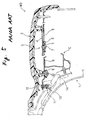
- conventional steering wheels employ a construction such that the constituent parts of the horn switch are arranged in a distributed manner so that a large space is required for mounting the horn switch.
- the freedom of arrangement of other function parts within the steering wheel has been limited, and the space below a horn pad could not be utilized efficiently.
- a steering wheel comprising a steering wheel body , a horn pad provided above said steering wheel body , and a plurality of horn switches forming part of a horn operating circuit provided between said horn pad and said steering wheel body, wherein each of said horn switches comprises an insulating spacer , a horn spring electrically connected to one electrode of said horn operating circuit, said horn spring being in contact with said horn pad to urge said horn pad upwardly , another contact portion electrically connected to another electrode of said horn operating circuit and disposed beneath said contact portion of said horn spring, and a shoulder bolt screw-mounted to said horn pad; sad spacer including a tubular portion with an insertion hole, said shoulder bolt including an axially extending shank which passes through said tubular portion; an externally threaded portion which extends from one end of said shank and is screw-mounted to said horn pad, and a head which is provided at the other end of said shank, said head having a diameter larger than the inner diameter of said tubular portion
- the insulating spacer is mounted on the steering wheel body by a plurality of screws which are arranged in the periphery of the spacer.
- the horn pad is, however, mounted at the insulating spacer by the shoulder bolt in which a screw is threaded.
- the spacer has a tubular portion with an enlarged retaining portion formed on an outer peripheral surface thereof at a distal end thereof.
- the spacer is fixed on the steering wheel body.
- the spacer actually performs two functions of an insulating spacer and of a mounting piece , thereby avoiding an additional fixing of the spacer on a plate with a screw or the like.
- the functions of the horn switch according to the invention are provided in a concentrated manner, and the horn switch itself has a compact construction. This assembly allows a proper preassembling of the switch with the horn pad and the spacer.
- the shank has to be longer than the tubular portion for guiding the motion of the horn pad by sliding this in the tubular portion.
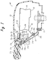
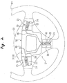
- a preferred embodiment of a steering wheel W1 of the present invention includes three horn switches 23 located between a steering wheel body 21 and a horn pad 22.
- the steering wheel body 21 includes those constituent portions of the steering wheel W1 except for the horn pad 22, the horn switches 23 and an impact energy absorber 32 (described later).
- the steering wheel body 21 comprises a metal core member 21a (described later), a covering layer 21c of a soft synthetic resin, such as urethane, covering part of the metal core member 21a and having a retaining hole 21b, and a lower cover 21d.
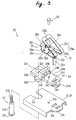
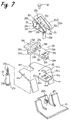
- each of the horn switches 23 comprises a spacer 24 having an insulating property, a horn spring 25 electrically connected to a positive electrode of a horn operating circuit, a tongue 26 for grounding purposes electrically connected to a negative electrode of the horn operating circuit, and a stepped shoulder belt 27.
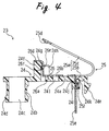
- the spacer 24 in the horn switch 23 is made of a synthetic resin such as polyacetal, and includes a base plate 24a extending horizontally, a cylindrical tubular portion 24b formed at one end of the base plate 24a, and a retaining leg 24e formed at the other end of the base plate 24a and extending downwardly therefrom.
- the tubular portion 24b has an insertion hole or bore 24c extending vertically therethrough, and also has an annular convex portion 24d formed on the lower end of an outer periphery thereof.
- a mounting projection 24f having a step surface 24g, extends upwardly from the base portion 24a adjacent the tubular portion 24b.
- a pair of limiting projections 24h extend upwardly from the base plate 24a adjacent the mounting projection 24f, and are disposed on opposite sides of the base plate 24a, respectively.
- a mounting portion 24i having a rectangular cross-section, extends downwardly from the bottom of base plate 24a adjacent the retaining leg 24e, and has an insertion hole 24j extending vertically therethrough.
- a step surface or shoulder 24k shown in Fig. 4, is formed on the inner surface of the insertion hole 24j intermediate opposite ends thereof.
- a hole 24l is formed vertically through a central portion of the base plate 24a.
- the retaining leg 24e serves to provisionally retain the spacer 24 on a base plate 31 (described later), and is formed into such a narrow shape that it can be easily broken upon reception of an impact force as will be described later.
- the horn spring 25 is made of spring steel, and includes a body 25a of a generally U-shape having a base portion 25b extending horizontally and a contact portion 25c extending obliquely upwardly from one end of the base portion 25b.
- a mounting piece portion 25e extends downwardly from the body 25a.
- a recessed portion serving as a contact 25d is formed at an upper end portion of the contact portion 25c, and a pawl 25f is formed on the mounting piece portion 25e intermediate upper and lower ends thereof.
- a projection piece 22b shown in Fig. 1, is provided on the back surface of the horn pad 22 and is adapted to be abutted against the upper surface of the horn spring 25 in the vicinity of the contact 25d.
- the horn spring 25 is mounted on the base plate 24a of the spacer 24 by inserting the mounting piece portion 25e into the insertion hole 24j in the mounting portion 24i so that the pawl 25f is retainingly engaged with the step surface 24k.
- a terminal 29 having a lead wire 28 connected thereto is connected to the lower end portion of the mounting piece portion 25e to thereby electrically connect the horn spring 25 to the positive electrode of the horn operating circuit.
- the tongue 26 is made of spring steel, and includes a pair of horizontally-extending lower and upper plate portions 26a and 26d, and a vertical plate portion 26e interconnecting the lower and upper plate portions 26a and 26d.
- the upper plate portion 26d serves as a contact for cooperating with the contact portion 25c of the horn spring 25.
- a through hole 26b is formed in a generally central portion of the lower plate portion 26a, and a pair of through holes 26c are formed in opposite (right and left) side portions of the lower plate portion 26a adjacent to the vertical plate portion 26e.
- a pawl 26f is formed on the vertical plate portion 26e.
- the tongue 26 is mounted on the base plate 24a of the spacer 24 by passing each of the limiting projections 24h and 24h of the spacer base plate 24a respectively through one of the through holes 26c and 26c in the lower plate portion 26a and by retainingly engaging the pawl 26f of the vertical portion 26e with the step surface 24g of the mounting projection 24f.
- the tongue 26 is fixedly secured to the base plate 31 by a rivet 30 passing through the through hole 26b and the through hole 24l (formed in the spacer 24) aligned with each other, so that the tongue 26 is electrically connected to the negative electrode of the horn operating circuit via the rivet 30 and the base plate 31 (impact energy absorber 32 described later).
- the rivet 30 is made of a metal material (e.g. aluminum) that can be sheared.
- the base plate 31 in this embodiment constitutes an upper plate portion 33 of the impact energy absorber 32 made of a metal sheet.
- the impact energy absorber 32 includes the upper plate portion 33 (base plate 31), a lower plate portion 34, and a deformation portion 36 interconnecting the upper and lower plate portions 33 and 34.
- the deformation portion 36 can be buckled and deformed to absorb impact energy.
- a through hole 31a is formed for the rivet 30, along with a retaining hole 31b for retainingly receiving the retaining leg 24e of the spacer 24 to provisionally retain the spacer 24 on the base plate 31, an opening 31c for the tubular portion 24b of the spacer 24, and an insertion hole 31d for the mounting tubular portion 24i of the spacer 24.
- a mounting piece 35 comprised of a metal sheet having an internally-threaded portion 35a secured thereto, is formed on the lower plate portion 34 of the impact energy absorber 32.
- the mounting piece 35 is secured to the metal core member 21a of the steering wheel body 21 by a bolt 37 which passes through the core metal member 21a from a reverse side thereof, and is screw-mounted to the internally-threaded portion 35a.
- the impact energy absorber 32 is electrically connected to the core metal member 21a serving as the negative (grounding) side of the horn operating circuit.
- the bolts 37 prevent the impact energy absorber 32 from being disengaged from the steering wheel body 21.
- the shoulder bolt 27 includes a shank 27a, an externally-threaded portion 27b, and a head 27c.
- the shank 27a is longer than the tubular portion 24b, and passes through the tubular portion 24b of the spacer 24.
- the externally-threaded portion 27b extends upwardly from one end of the shank 27a, and is screw-mounted into a boss 22a provided on the horn pad 22.
- the head 27c is formed at the other end of the shank 27a. The diameter of the head 27c is larger than an inner diameter of the insertion hole 24c of tubular portion 24b, but is smaller than the outer diameter of the convex portion 24d.
- the length of that portion of the shank 27a projecting outwardly from the tubular portion 24b is longer than a horn stroke, that is, the distance by which the contact portion 25c, specifically the contact 25d, of the horn spring 25 would be brought into contact with the contact portion 26d when the horn pad 22 is pressed down for operating the horn.
- the horn spring 25 and the tongue 26 are held on the associated spacer 24 through their respective pawls 25f and 26f as described above. Then, the mounting portion 24i of the spacer 24 is inserted into the hole 31d, and also the retaining leg 24e is engaged in the hole 31b, thereby provisionally retaining the spacer 24 on the base plate 31 of the impact energy absorber 32. Then, the spacer 24 is secured to the base plate 31 by the rivet 30, and the lead wire 28 is connected to the mounting piece portion 25e of the horn spring 25 through the terminal 29.
- the externally-threaded portion 27b of the shoulder bolt 27 is screwed into the associated boss 22a of the horn pad 22 through the insertion hole 24c in the tubular portion 24b from the lower side thereof.
- the three horn switches 23 and one impact energy absorber 32 are attached to the horn pad 22.
- the projection 22b projecting downwardly from the horn pad 22 is abutted against an upper surface of the horn spring 25 in the vicinity of the contact 25d.
- each lead wire 28 is connected to a slip ring (not shown) of the steering wheel body 21, and the tubular portion 24b of each spacer 24 is inserted into the associated retaining hole 21b in the steering wheel body 21, and each bolt 37 is screwed to the internally-threaded portion 35a of the associated mounting piece 35 of the impact energy absorber 32.
- the horn pad 22, the horn switches 23 and the impact energy absorber 32 are attached to the steering wheel body 21, thus completing the assembling of the steering wheel W1.
- the steering wheel body 21 has been mounted on a steering shaft (not shown) mounted on the vehicle.
- the shank 27a of the shoulder bolt 27 is moved along and relative to the insertion hole 24c in the tubular portion 24b.
- the head 27c is also moved downward along the retaining hole 21b in the steering wheel body 21.
- the body 25a of the horn spring 25 is bent by the projection 22b of the horn pad 22, so that the contact 25d of the contact portion 25c comes into contact with the contact portion 26d of the associated tongue 26, thereby operating the horn.
- each spacer 24 holds the associated horn spring 25 and tongue 26 in an insulated manner and mounts them onto the steering wheel body 21 through the tubular portion 24b.
- the shoulder bolt 27 also passes through the tubular portion 24b of the spacer 24 to hold the horn pad 22, and guides the downward movement of the horn pad 22.
- each of horn switches 3 provided between a steering wheel body 1 and the horn pad 2 comprises nine component parts, that is, a horn spring 4, insulating spacers 5 and 6, a rivet 7, a base plate 8, a guide spacer 9, a screw 10, a mounting piece 11, and a screw 12.
- the horn spring 4 is attached to the base plate 8 by the rivet 7 through the insulating spacers 5 and 6, and urges the horn pad 2 upwardly.
- the horn spring 4 is electrically connected to a positive electrode of a horn operating circuit via the rivet 7.
- the base plate 8 constitutes an upper portion of an impact energy absorber E formed of a metal sheet, and is electrically connected to a negative electrode of the horn operating circuit via a core metal member la of the steering wheel body 1.
- the guide spacer 9 is attached to a back surface of the horn pad 2 by the screw 10 passing through the base plate 8 from the lower side thereof, and guides the downward movement of the horn pad 2 when the horn is operated.
- the guide spacer 9 also prevents the horn pad 2 from being disengaged from the base plate 8.
- the mounting piece 11 is attached to a back surface of the base plate 8 by the screw 12, and is inserted and retained in a retaining hole lb in the steering wheel body 1.
- the mounting piece 11 connects the horn spring 4 of the horn switch 3 mounted on the base plate 8, as well as the horn pad 2, to the steering wheel body 1.
- the number of the component parts of the conventional horn switch 3 is nine as described above whereas the horn switch of this embodiment comprises six component parts, that is, the spacer 24, the horn spring 25, the tongue 26, the shoulder bolt 27, the rivet 30 and the base plate 31.
- the rivet 30 also does not need to be used, and therefore the number of the component parts is reduced to four, that is, the spacer 24, the horn spring 25, the tongue 26 and the shoulder bolt 27.
- the horn switch 23 can achieve its function without any inconvenience if a predetermined lead wire is connected to the tongue 26, since the base plate 24a of the spacer 24 is secured to a peripheral edge of the retaining hole 21b in the steering wheel body 21 through the tubular portion 24b.
- the horn spring 25 and the tongue 26 are mounted on the same spacer 24, and the shoulder bolt 27, which holds the horn pad 22, and guides the downward movement of the horn pad 22, is received in the spacer 24.
- the functions of the horn switch 23 are provided in a concentrated manner, and the horn switch 23 can itself have a compact construction.
- the spacer 24 performs the function of insulating spacers 5 and 6 of a conventional construction, and also performs the function of the mounting piece 11. Further, the shoulder bolt 27 performs the function of holding a conventional horn pad (i.e., the function of the screw 10), and also performs the function of the guide spacer 9. Therefore, in the steering wheel W1 of this embodiment, the number and kinds of constituent or component parts is reduced.
- the reduced parts allows the horn switch 23 to be arranged in a compact manner, so that space below the horn pad 22 can be efficiently utilized.
- the body 25a of each of the horn springs 25 urging the horn pad 22 upwardly has a recumbent U-shape, and therefore unlike the conventional horn switch 4, the horn switch 23 can be compact in configuration as viewed from above it, and therefore the spacer 24 holding the horn spring 25 mounted thereon can also be compact in configuration as viewed from above it, so that the horn switch 23 can be of a more compact construction.
- the spacers 24 are designed to be mounted on the large base plate 31 of a metal sheet, and the base plate 31 is designed to serve as part of the circuit leading to the negative electrode of the horn operating circuit, in this embodiment. In this case, when the plurality of horn switches 23 are to be mounted on the steering wheel W1, all of the spacers 24 can be mounted on the base plate 31.
- the mounting operations such as screw-mounting of shoulder bolt 27 to the horn pad 22 through the tubular portion 24b of the associated spacer 24, and the insertion of the tubular portion 24b of each spacer 24 into the associated retaining hole 21b in the steering wheel body 21, can be carried out smoothly since the displacement of the tubular portion 24b of each spacer 24 out of position can be prevented by the base plate 31 of a metal sheet having a certain degree of shape retention nature.
- all of the horn switches 23 are electrically connected to the negative electrode of the horn operating circuit by the common member, that is, by base plate 31, time and labor for wiring can both be saved.
- the impact energy absorber 32 incorporates therein the base plate 31, as in this embodiment, there is no need to provide a separate base plate.
- the impact energy absorber 32 incorporates therein the base plate 31, since a rivet 30 that can be sheared is used for securing the spacer 24 to the base plate 31, when an impact force is applied to the horn pad 22, the rivet 30 is sheared (in which case the easily-breakable retaining leg 24e is also broken), so that the connection between the upper plate portion 33 (the base plate 31) of the impact energy absorber 32 and the steering wheel body 21 is broken even though the spacer 24 is connected to the steering wheel body 21 through the tubular portion 24b, and as a result a deformation portion 36 can be easily buckled and deformed, thereby effectively absorbing the energy of the impact force.
- the horn switches 23 of a compact construction are arranged at the outer peripheral portion of the horn pad 22 as in this embodiment, a large space can be obtained below the central portion of the horn pad 22. Therefore even when an impact force acts on the central portion of the horn pad 22, since the horn switches 23 do not affect the deformation portion 36 of the impact energy absorber 32, such portion can absorb substantially all of the energy of the impact force, thus enhancing an energy absorbing efficiency of the impact energy absorber 32.
- the horn spring 25 and the tongue 26 are retained on the spacer 24 by their respective pawls 25f and 26f
- another retaining approach can alternatively be used.
- thermal caulking can be employed, in which mounting projections are formed on the base plate 24a of the spacer 24, and these mounting projections are inserted into the mounting through holes formed in the horn spring 25 and the tongue 26, and then projected distal ends of these mounting projections are expanded.
- the spacer 24 may be molded to directly incorporate the horn spring 25 and the tongue 26 therein as molded inserts.
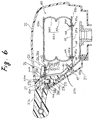
- the supporting bracket 38 for the horn switch 23 is made of metal sheet and as shown in Fig. 6, includes a bottom 39, three mounting portions 40 (only one is shown), three arms 41 (only one is shown), and three supporting stages 42 (only one is shown).
- the bottom 39 is provided with mounting holes 39a through which an impact energy absorber 43 which will be described later in detail is mounted on the bottom 39 by means of bolts 37.
- the bottom 39 is also provided at a center portion thereof with a lightening hole 39b so as to be readily deformed. Accordingly, the bottom 39 presents a triangle frame shape.
- the mounting portions 40 extend from the bottom 39, through which the supporting bracket 38 is mounted on the steering wheel body 21.
- the mounting portion 40 is fixedly screwed onto the metal core member 21a of the steering wheel body 21 by means of the bolt 37 which engages with a threaded portion 40a formed in the mounting portion 40.
- the mounting portion 40 is made by punching out and bending up one end part of the arm 41.
- Three arms 41 extend from the respective vertex portions of the triangle shaped bottom 39 to the corresponding horn switches 23.
- the supporting stage 42 is divided into a radially outer part 42a and a radially inner part 42b by a border line along which an end 41a of the arm 41 is integrated into the supporting stage 42.
- the supporting stage 42 is made by partially punching and bending the other end part of the arm 41.
- the outer parts 42a of the supporting stages 42 are abutted onto supporting flats 21d of the steering wheel body 21 while the inner parts 42b extend radially inward and are free from the metal core members 21a and the supporting flats 21d of the steering wheel body 21.
- the outer part 42a of the mounting portion 40 is provided with a notch 42f for receiving the tubular portion 24b of the spacer 24.
- the inner part 42b of the mounting portion 40 is provided with a circular through hole 42c for the rivet 30, a rectangular through hole 42d engaged with the retaining leg 24e of the spacer 24 for temporally retaining the spacer 24 on the supporting stage 42, and a rectangular through hole 42e into which the mounting projection 24i is inserted.
- the impact energy absorber 43 is made of metal sheet, and includes an upper plate portion 43a, a lower plate portion 43b, and a deformable portion 43c inter-connecting the plate portions 43a and 43b.
- the lower plate portion 43b is provided with threaded portions 43d which correspond to the mounting holes 39a of the bottom 39.
- the impact energy absorber 43 is fixedly mounted on the bottom 39 by tightening up bolts 44.
- the deformable portion 43c includes a plastically deformable part 43e and a readily plastically deformable part 43f, whose thicknesses are difference from each other so as to effectively absorb an impact force regardless of an magnitude thereof. In case of the same thickness in these parts 43e and 43f, it may be possible to provide a larger lightening hole to the readily plastically deformable part 43f so as to make it more deformable than the deformable part 43e.
- the bottom 39 is so readily deformed that the impact energy absorber 43 is also deformed to absorb an energy of the impact force F.
- the readily plastically deformable part 43f is deformed to absorb it.
- the impact energy absorber 43 can absorb the impact force of wider range of magnitude thereof.
- a plurality of horn switches (23) are provided between a steering wheel body (21) and a horn pad (22) provided above the steering wheel body.
- Each of the horn switches includes a spacer (24) having an insulating property, a horn spring (25) which is connected to a positive electrode of a horn operating circuit and urges the horn pad upwardly, a tongue (26) connected to a negative electrode of the horn operating circuit, and a shearable shoulder bolt (27).
- the horn spring and the tongue are mounted on the spacer.
- the spacer has a tubular portion (24b) having an enlarged portion (24d) formed on an outer peripheral surface thereof at a distal end thereof. The tubular portion is retained in a retaining hole (21b) in the steering wheel body.
- the shoulder bolt is inserted into the tubular portion from an end thereof opposite to the horn pad, and is screw-mounted to the horn pad.
Landscapes
- Physics & Mathematics (AREA)
- Acoustics & Sound (AREA)
- Engineering & Computer Science (AREA)
- Mechanical Engineering (AREA)
- Steering Controls (AREA)
- Push-Button Switches (AREA)
Claims (9)
- Ein Steuerrad hatein Steuerradgehäuse (21),eine Hupenkonsole (22), die oberhalb des Steuerradgehäuses angeordnet ist; und
eine Vielzahl Hupenschalter (23), die einen Teil einer Hupenbetätigungsschaltung ausbilden und Zwischen der Hupenkonsole und dem Steuerradgehäuse angeordnet sind, wobei jeder der Hupenschalter einen isolierenden Abstandhalter (24) hat, der einen röhrenförmigen Abschnitt (24b) mit einem Einführloch (24c) hat, eine Hupenfeder (25), die elektrisch mit einer Elektrode der Hupenbetätigungsschaltung verbunden ist, wobei die Hupenfeder in Kontakt mit der Hupenkonsole ist, um die Hupenkonsole in aufwärtige Richtung vorzuspannen, einen anderen Kontaktabschnitt (26d), der elektrisch mit einer anderen Elektrode der Hupenbetätigungsschaltung verbunden ist und unterhalb des Kontaktabschnitts der Hupenfeder angeordnet ist, und einen Bundbolzen (27), der an der Hupenkonsole schraubbefestigt ist und einen sich in Axialrichtung erstreckenden Schaft (27a) hat, der durch den röhrenformigen Abschnitt reicht, einen Außengewindeabschnitt (27b), der sich von einem Ende des Schaftes erstreckt und an der Hupenkonsole (22) schraubbefestigt ist, und einen Kopf, der an dem anderen Ende des Schaftes vorgesehen ist, wobei der Kopf einen Durchmesser hat, der größer als der Innendurchmesser des röhrenförmigen Abschnittes ist; wobei die Hupenfeder auf dem Abstandhalter auf isolierende Weise angeordnet ist, und wobei der röhrenförmige Abschnitt in eine Aufnahmebohrung (21b) eingeführt wird, die in dem Steuerradgehäuse vorgesehen ist, und wobei der Bundbolzen in den röhrenförmigen Abschnitt von einem Ende aus, gegenüberliegend der Hupenkonsole, eingeführt und bewegbar entlang des und relativ zu dem Einführloch ist, dadurch gekennzeichnet, daß der andere Kontaktabschnitt auf einer Lasche (26) ausgebildet ist, die elektrisch mit einer anderen Elektrode verbunden ist, wobei die Lasche (26) auf dem Abstandhalter angeordnet ist, und wobei der röhrenförmige Abschnitt (24b) einen vergrößerten Halteabschnitt (24d) hat, der auf einer äußeren Umfangsfläche davon an einem entfernten Ende davon ausgebildet ist, um den röhrenförmigen Abschnitt in der Haltebohrung zu halten, wobei der Schaft länger als der röhrenförmige Abschnitt ist. - Steuerrad nach Anspruch 1, bei dem der Abstandhalter fest auf einer Grundplatte (31) montiert ist, die eine Metallschicht hat, und wobei die Grundplatte einen Teil der Hupenbetätigungsschaltung bildet.
- Steuerrad nach Anspruch 2, bei dem die Grundplatte einen Teil des Aufprallenergieabsorbers (32) bildet.
- Steuerrad nach Anspruch 3, wobei der Abstandhalter durch einen Niet (30), der geschert werden kann, montiert ist.
- Steuerrad nach Anspruch 1, bei dem der Abstandhalter fest auf einem Halteabschnitt (42) montiert ist, der eine Metallschicht hat, wobei die Grundplatte einen Teil der Hupenbetätigungsschaltung bildet.
- Steuerrad nach Anspruch 5, bei dem der Halteabschnitt einen Teil eines Haltearmes (38) für einen Aufprallenergieabsorber (43) bildet.
- Steuerrad nach Anspruch 6, bei dem der Haltearm einen Boden (39) hat, eine Vielzahl Montageabschnitte (40), die sich von dem Boden erstrecken, die an dem Steuerradgehäuse befestigt sind, eine Vielzahl Arme (41), die sich von dem Boden zu den betreffenden Hupenschaltern erstrecken, und eine Vielzahl Halteabschnitte (42), die jeweils mit dem betreffenden Arm verbunden sind.
- Steuerrad nach Anspruch 7, bei dem der Boden Montagelöcher (39a), durch die der Aufprallenergieabsorber fest auf dem Boden befestigt ist, und ein Erleichterungsloch (39b) hat.
- Steuerrad nach Anspruch 3, bei dem der Aufprallenergieabsorber einen oberen Plattenabschnitt (43a), einen unteren Plattenabschnitt (43b) und einen verformbaren Abschnitt (43c) hat, der diese Abschnitte miteinander verbindet.
Applications Claiming Priority (4)
| Application Number | Priority Date | Filing Date | Title |
|---|---|---|---|
| JP6233391A JP3000861B2 (ja) | 1994-09-28 | 1994-09-28 | ステアリングホイール |
| JP233391/94 | 1994-09-28 | ||
| JP06277895A JP3214286B2 (ja) | 1995-03-22 | 1995-03-22 | ステアリングホイール |
| JP62778/95 | 1995-03-22 |
Publications (2)
| Publication Number | Publication Date |
|---|---|
| EP0704367A1 EP0704367A1 (de) | 1996-04-03 |
| EP0704367B1 true EP0704367B1 (de) | 1998-08-26 |
Family
ID=26403837
Family Applications (1)
| Application Number | Title | Priority Date | Filing Date |
|---|---|---|---|
| EP95115232A Expired - Lifetime EP0704367B1 (de) | 1994-09-28 | 1995-09-27 | Lenkrad |
Country Status (4)
| Country | Link |
|---|---|
| US (1) | US5627352A (de) |
| EP (1) | EP0704367B1 (de) |
| CN (1) | CN1063397C (de) |
| DE (1) | DE69504264T2 (de) |
Families Citing this family (28)
| Publication number | Priority date | Publication date | Assignee | Title |
|---|---|---|---|---|
| IT1284667B1 (it) * | 1996-07-16 | 1998-05-21 | Bruzolo Manifatt Gestind Mb | Volante di sterzo per autoveicoli con interruttore per il comando di di un avvisatore acustico. |
| DE29805207U1 (de) | 1998-03-23 | 1998-06-04 | TRW Automotive Safety Systems GmbH, 63743 Aschaffenburg | Lenkrad mit Airbag |
| DE29805210U1 (de) | 1998-03-23 | 1998-06-04 | TRW Automotive Safety Systems GmbH, 63743 Aschaffenburg | Aufprall-Schutzvorrichtung |
| JPH11297155A (ja) * | 1998-04-07 | 1999-10-29 | Takata Kk | ステアリングデバイス |
| DE19819695C2 (de) * | 1998-05-02 | 2000-12-07 | Eaton Controls Gmbh | Lenkradschalter für ein Kraftfahrzeug |
| DE29906374U1 (de) | 1999-04-09 | 1999-06-24 | TRW Automotive Safety Systems GmbH & Co.KG, 63743 Aschaffenburg | Lenkrad mit Airbagmodul und Hupkontakt |
| DE29906377U1 (de) * | 1999-04-09 | 1999-06-17 | TRW Automotive Safety Systems GmbH & Co.KG, 63743 Aschaffenburg | Lenkrad mit Airbagmodul |
| IT1308842B1 (it) * | 1999-09-24 | 2002-01-11 | Gallino Plasturgia S R L | Dispositivo di azionamento di avvisatore acustico per un volante diazionamento. |
| JP4581244B2 (ja) * | 2000-01-14 | 2010-11-17 | タカタ株式会社 | エアバッグ装置及びステアリングホイール |
| DE20006595U1 (de) * | 2000-04-10 | 2000-08-17 | TRW Automotive Safety Systems GmbH & Co. KG, 63743 Aschaffenburg | Fahrzeuglenkrad |
| JP3789284B2 (ja) * | 2000-04-28 | 2006-06-21 | アルプス電気株式会社 | 車両のハンドル用スイッチユニット |
| US6830263B2 (en) * | 2002-02-08 | 2004-12-14 | Key Safety Systems, Inc. | Method for attaching an airbag module |
| EP1415857A2 (de) * | 2002-10-30 | 2004-05-06 | TRW Automotive Safety Systems GmbH | Fahrzeuglenkrad |
| US7159897B2 (en) * | 2003-07-21 | 2007-01-09 | Delphi Technologies, Inc. | Isolated ground for horn mechanism |
| DE20315868U1 (de) * | 2003-10-15 | 2004-02-26 | Trw Automotive Safety Systems Gmbh | Lenkradhupenkontakteinheit und Baugruppe |
| US7159898B2 (en) * | 2004-04-20 | 2007-01-09 | General Motors Corporation | Vehicle air bag module retention system |
| JP2007035609A (ja) * | 2004-12-10 | 2007-02-08 | Takata Corp | ホーンスイッチ装置、エアバッグ装置及びステアリングホイール |
| JP2006228699A (ja) * | 2004-12-17 | 2006-08-31 | Takata Corp | ホーンスイッチ装置、エアバッグ装置及びステアリングホイール |
| ES2301340B1 (es) * | 2006-03-13 | 2009-05-01 | Dalphi Metal España S.A. | Volante de automovil con claxon pivotante. |
| DE102008062421A1 (de) * | 2008-12-17 | 2010-07-08 | Autoliv Development Ab | Lenkradeinheit |
| CN102762416B (zh) * | 2010-02-18 | 2016-08-31 | Trw汽车安全系统有限公司 | 带有气袋模块的方向盘 |
| WO2013070905A1 (en) * | 2011-11-09 | 2013-05-16 | Key Safety Systems Inc. | Snap in driver side airbag module assembly |
| US9308930B2 (en) * | 2012-04-06 | 2016-04-12 | Autoliv Asp, Inc. | Steering wheel with switch assembly |
| CN103507849B (zh) * | 2013-10-28 | 2015-12-02 | 重庆长安汽车股份有限公司 | 一种汽车方向盘 |
| KR102394806B1 (ko) * | 2017-11-29 | 2022-05-04 | 현대자동차주식회사 | 자동차의 혼 작동 장치 |
| CN115135559B (zh) * | 2020-03-23 | 2024-02-20 | 奥托立夫开发公司 | 方向盘 |
| KR20240033489A (ko) * | 2022-09-05 | 2024-03-12 | 현대자동차주식회사 | 스티어링휠과, 그 스티어링휠의 댐퍼유닛 |
| FR3167595A1 (fr) * | 2024-10-18 | 2026-04-24 | Autoliv Development Ab | Dispositif d’avertisseur sonore de véhicule |
Family Cites Families (16)
| Publication number | Priority date | Publication date | Assignee | Title |
|---|---|---|---|---|
| FR1471447A (fr) * | 1966-03-09 | 1967-03-03 | Flii Vitaloni | Interrupteur à bouton-poussoir |
| US3517145A (en) * | 1968-06-03 | 1970-06-23 | Gen Motors Corp | Padded steering wheel horn switch |
| US3589210A (en) * | 1969-05-27 | 1971-06-29 | Gen Motors Corp | Energy absorber |
| DE2740986C3 (de) * | 1977-09-12 | 1981-10-22 | Petri Ag, 8750 Aschaffenburg | Elektrische Kontakteinrichtung, insbesondere für Signaleinrichtungen von Kraftfahrzeugen |
| FR2470718A1 (fr) * | 1979-12-03 | 1981-06-12 | Planchard Jean Michel | Dispositif de calage de charge, notamment pour wagons transport de vehicules |
| DE3722069A1 (de) * | 1986-08-21 | 1988-02-25 | Toyoda Gosei Kk | Signalhornschaltvorrichtung fuer ein steuerrad |
| US4872364A (en) * | 1987-10-27 | 1989-10-10 | Toyoda Gosei Co., Ltd. | Steering wheel |
| US5067367A (en) * | 1988-11-30 | 1991-11-26 | Toyoda Gosei Co., Ltd. | Steering wheel |
| JPH0710993Y2 (ja) * | 1989-03-27 | 1995-03-15 | 豊田合成株式会社 | ステアリングホイールのホーンスイツチ |
| JPH0710994Y2 (ja) * | 1989-03-27 | 1995-03-15 | 豊田合成株式会社 | ステアリングホイールのホーンスイツチ |
| JP2581336B2 (ja) * | 1991-04-30 | 1997-02-12 | 豊田合成株式会社 | 衝撃エネルギー吸収体を備えたステアリングホイール |
| JPH0818560B2 (ja) * | 1991-05-29 | 1996-02-28 | 日本プラスト株式会社 | ステアリングホイールのホーンスイッチ装置 |
| JP2658694B2 (ja) * | 1991-11-20 | 1997-09-30 | 豊田合成株式会社 | ステアリングホイールのホーンスイツチ |
| US5239147A (en) * | 1992-08-03 | 1993-08-24 | Morton International, Inc. | Floating, serviceable horn switch, air bag modules |
| US5410114A (en) * | 1992-12-25 | 1995-04-25 | Toyoda Gosei Co., Ltd. | Steering wheel horn switch mechanism |
| US5327796A (en) * | 1992-12-28 | 1994-07-12 | General Motors Corporation | Horn switch actuated by rocking air bag module |
-
1995
- 1995-09-22 US US08/532,269 patent/US5627352A/en not_active Expired - Lifetime
- 1995-09-27 DE DE69504264T patent/DE69504264T2/de not_active Expired - Fee Related
- 1995-09-27 EP EP95115232A patent/EP0704367B1/de not_active Expired - Lifetime
- 1995-09-28 CN CN95115660A patent/CN1063397C/zh not_active Expired - Fee Related
Also Published As
| Publication number | Publication date |
|---|---|
| CN1127206A (zh) | 1996-07-24 |
| CN1063397C (zh) | 2001-03-21 |
| EP0704367A1 (de) | 1996-04-03 |
| US5627352A (en) | 1997-05-06 |
| DE69504264D1 (de) | 1998-10-01 |
| DE69504264T2 (de) | 1999-03-11 |
Similar Documents
| Publication | Publication Date | Title |
|---|---|---|
| US5627352A (en) | Steering wheel | |
| US6953204B2 (en) | Switch assembly for an airbag module attachment | |
| CN1833922B (zh) | 带气囊装置的方向盘 | |
| EP1268240B1 (de) | Schnappbefestigung für fahrer-airbagmodul | |
| US6600114B2 (en) | Steering wheel horn switch | |
| EP1493622B1 (de) | Hupenschalter und Gassackvorrichtung | |
| US20010030412A1 (en) | Airbag apparatus | |
| US4590340A (en) | Steering wheel assembly for vehicles | |
| JP3572697B2 (ja) | エアバッグ装置を備えたステアリングホイール | |
| US6481745B2 (en) | Driver Air bag module horn with improved assembly and functionality characteristics | |
| JPWO2007013635A1 (ja) | エアバッグ装置 | |
| JP3000861B2 (ja) | ステアリングホイール | |
| JP3436895B2 (ja) | ステアリングホイール | |
| US7316414B2 (en) | Housing for an airbag module | |
| JP3276508B2 (ja) | ステアリングホイール | |
| KR0158788B1 (ko) | 스티어링 휘일 | |
| JP2001278065A (ja) | 車両用ステアリング装置 | |
| JP2001063588A (ja) | ステアリングホイール | |
| JPH08258721A (ja) | ステアリングホイール | |
| JP3468146B2 (ja) | 車両のエアバッグモジュール | |
| EP4559780A1 (de) | Struktur zur befestigung eines airbagmoduls an einem lenkrad | |
| JP4018846B2 (ja) | ステアリングホイール | |
| WO2023181080A1 (en) | A switch assembly for a vehicle | |
| JPH0716541Y2 (ja) | 衝撃エネルギー吸収体を備えたステアリングホイール | |
| JP2000318561A (ja) | エアバッグ装置 |
Legal Events
| Date | Code | Title | Description |
|---|---|---|---|
| PUAI | Public reference made under article 153(3) epc to a published international application that has entered the european phase |
Free format text: ORIGINAL CODE: 0009012 |
|
| 17P | Request for examination filed |
Effective date: 19950927 |
|
| AK | Designated contracting states |
Kind code of ref document: A1 Designated state(s): DE FR GB |
|
| 17Q | First examination report despatched |
Effective date: 19960508 |
|
| GRAG | Despatch of communication of intention to grant |
Free format text: ORIGINAL CODE: EPIDOS AGRA |
|
| GRAG | Despatch of communication of intention to grant |
Free format text: ORIGINAL CODE: EPIDOS AGRA |
|
| GRAH | Despatch of communication of intention to grant a patent |
Free format text: ORIGINAL CODE: EPIDOS IGRA |
|
| GRAH | Despatch of communication of intention to grant a patent |
Free format text: ORIGINAL CODE: EPIDOS IGRA |
|
| GRAA | (expected) grant |
Free format text: ORIGINAL CODE: 0009210 |
|
| AK | Designated contracting states |
Kind code of ref document: B1 Designated state(s): DE FR GB |
|
| REF | Corresponds to: |
Ref document number: 69504264 Country of ref document: DE Date of ref document: 19981001 |
|
| ET | Fr: translation filed | ||
| PLBE | No opposition filed within time limit |
Free format text: ORIGINAL CODE: 0009261 |
|
| STAA | Information on the status of an ep patent application or granted ep patent |
Free format text: STATUS: NO OPPOSITION FILED WITHIN TIME LIMIT |
|
| 26N | No opposition filed | ||
| PGFP | Annual fee paid to national office [announced via postgrant information from national office to epo] |
Ref country code: FR Payment date: 20010911 Year of fee payment: 7 |
|
| PGFP | Annual fee paid to national office [announced via postgrant information from national office to epo] |
Ref country code: GB Payment date: 20010926 Year of fee payment: 7 |
|
| REG | Reference to a national code |
Ref country code: GB Ref legal event code: IF02 |
|
| PG25 | Lapsed in a contracting state [announced via postgrant information from national office to epo] |
Ref country code: GB Free format text: LAPSE BECAUSE OF NON-PAYMENT OF DUE FEES Effective date: 20020927 |
|
| GBPC | Gb: european patent ceased through non-payment of renewal fee |
Effective date: 20020927 |
|
| PG25 | Lapsed in a contracting state [announced via postgrant information from national office to epo] |
Ref country code: FR Free format text: LAPSE BECAUSE OF NON-PAYMENT OF DUE FEES Effective date: 20030603 |
|
| REG | Reference to a national code |
Ref country code: FR Ref legal event code: ST |
|
| PGFP | Annual fee paid to national office [announced via postgrant information from national office to epo] |
Ref country code: DE Payment date: 20081002 Year of fee payment: 14 |
|
| PG25 | Lapsed in a contracting state [announced via postgrant information from national office to epo] |
Ref country code: DE Free format text: LAPSE BECAUSE OF NON-PAYMENT OF DUE FEES Effective date: 20100401 |