EP0704631A1 - Wegeventil in Mono-Blockbauweise mit seitlicher Bypassleitung - Google Patents
Wegeventil in Mono-Blockbauweise mit seitlicher Bypassleitung Download PDFInfo
- Publication number
- EP0704631A1 EP0704631A1 EP19950630075 EP95630075A EP0704631A1 EP 0704631 A1 EP0704631 A1 EP 0704631A1 EP 19950630075 EP19950630075 EP 19950630075 EP 95630075 A EP95630075 A EP 95630075A EP 0704631 A1 EP0704631 A1 EP 0704631A1
- Authority
- EP
- European Patent Office
- Prior art keywords
- passage
- sections
- control valve
- bypass passage
- valve body
- Prior art date
- Legal status (The legal status is an assumption and is not a legal conclusion. Google has not performed a legal analysis and makes no representation as to the accuracy of the status listed.)
- Withdrawn
Links
- 230000007935 neutral effect Effects 0.000 claims description 8
- 238000010276 construction Methods 0.000 description 3
- 238000004519 manufacturing process Methods 0.000 description 2
- 238000007792 addition Methods 0.000 description 1
- 230000000694 effects Effects 0.000 description 1
- 230000004048 modification Effects 0.000 description 1
- 238000012986 modification Methods 0.000 description 1
- 238000006467 substitution reaction Methods 0.000 description 1
Images


Classifications
-
- F—MECHANICAL ENGINEERING; LIGHTING; HEATING; WEAPONS; BLASTING
- F15—FLUID-PRESSURE ACTUATORS; HYDRAULICS OR PNEUMATICS IN GENERAL
- F15B—SYSTEMS ACTING BY MEANS OF FLUIDS IN GENERAL; FLUID-PRESSURE ACTUATORS, e.g. SERVOMOTORS; DETAILS OF FLUID-PRESSURE SYSTEMS, NOT OTHERWISE PROVIDED FOR
- F15B13/00—Details of servomotor systems ; Valves for servomotor systems
- F15B13/02—Fluid distribution or supply devices characterised by their adaptation to the control of servomotors
- F15B13/06—Fluid distribution or supply devices characterised by their adaptation to the control of servomotors for use with two or more servomotors
- F15B13/08—Assemblies of units, each for the control of a single servomotor only
-
- Y—GENERAL TAGGING OF NEW TECHNOLOGICAL DEVELOPMENTS; GENERAL TAGGING OF CROSS-SECTIONAL TECHNOLOGIES SPANNING OVER SEVERAL SECTIONS OF THE IPC; TECHNICAL SUBJECTS COVERED BY FORMER USPC CROSS-REFERENCE ART COLLECTIONS [XRACs] AND DIGESTS
- Y10—TECHNICAL SUBJECTS COVERED BY FORMER USPC
- Y10T—TECHNICAL SUBJECTS COVERED BY FORMER US CLASSIFICATION
- Y10T137/00—Fluid handling
- Y10T137/8593—Systems
- Y10T137/87169—Supply and exhaust
- Y10T137/87177—With bypass
- Y10T137/87185—Controlled by supply or exhaust valve
Definitions
- the present invention relates in general to a mono-block control valve used in hydraulic circuits and, more particularly, to a structural improvement in such a valve for substituting a side bypass passage for the typical center bypass passage, thereby improving the space efficiency of the valve and for connecting the right and left return passages to each other using the surplus space provided due to the side bypass passage and thereby reducing the passage resistance and achieving the stable operation of the valve.
- the actuators are operated by pressurized oil delivered from a hydraulic pump.
- the actuators are thus provided with their control valves.
- the mono-block control valve integrates the control valves for the actuators into a single body.
- the passages for connecting the control valves are formed in the single body of the mono-block control valve so that the mono-block control valve can simplify the valve structure, achieve the recent trend of compactness of the valves and remarkably improve the durability of the valves. Furthermore, as the mono-block control valve can be exclusively used differently from the separated Control valves commonly used, the mono-block control valve has been widely used.
- Fig. 1 is a longitudinally sectioned view of the control valve
- Fig. 2 is a cross sectioned view of the valve taken along the section line A-A' of Fig. 1.
- the mono-block control valve has a plurality of sections S1, S2 and S3, corresponding to control valves for the actuators respectively, in a single valve body B.
- the spool (not shown) of a section for example, the first section S1
- the pressurized oil is transmitted to a next section, for example, the second section S2, through a first bridge 106a.
- the center of the valve body B is provided with a center bypass passage 101 which is used for returning the pressurized oil to a return tank T without resistance when the spools of all the sections S1, S2 and S3 are placed in their neutral positions. When at least one of the spools of the sections S1, S2 and S3 moves, the center bypass passage 101 will be shut down.
- the valve body B also includes a parallel passage 103 for supplying the pressurized oil to the sections S1, S2 and S3 in parallel.
- the passage 103 is formed in the body D such that the passage 103 passes all of the sections S1, S2 and S3.
- the pressurized oil delivered from the pump P is supplied to or discharged from the left and right actuator ports 104 and 104' from or to the parallel passage 103 through a second bridge 106b.
- the pressurized oil discharged from the left and right actuators ports 104 and 104' returns to the return tank T through return passages 105 and 105' formed in the opposite outermost portions of the valve body B.
- the above mono-block control valve has a problem in that the valve B has five pump lines, which makes the passage structure of the body B a complicated three-dimensional structure.
- Another problem of the above control valve is resided in that the valve necessarily has the bridges 106a and 106b, connecting the pump lines, and thereby enlarging the valve body size and increasing the cost.
- the left and right return passages 105 and 105' passes the sections S1 and S2 and in turn are connected to each other through a connection passage 107 in the last section S3.
- the total length of the return passages 105 and 105' of the above mono-block control valve lengthens to increase the total passage resistance.
- there is a negative pressure difference between the left and right return passages 105 and 105' because the lengths of the return passages 105 and 105 extending from the actuator ports 104 and 104' to the return tank T are different from each other.
- the oil discharged from the right actuator port 104' rapidly returns to the tank T simply through the return passage 105' with little resistance.
- the oil discharged from the left actuator port 104 returns to the return tank T through a longer passage.
- the oil passes through return passage 105 extending in the sections S1 and S2 and in turn flows in the connection passage 107, making the two return passages 105 and 105' meeting one another. Thereafter, the oil returns to the tank T through the return passage 105'.
- Such a difference between the lengths of the return passages can not help causing the negative pressure difference between the two return passages 105 and 105'.
- the above control valve also causes pressure loss and unstable operation because the negative pressure in a specified section having a relatively longer return passage is remarkably higher than those of the other sections.
- an object of the present invention to provide an improved mono-block control valve in which the above problems can be overcome and which has a side bypass passage suitable for simplifying the passage structure of the valve body into a two-dimensional structure, thereby remarkably reducing the valve body size and improving the space efficiency and cutting down the cost.
- the present invention provides a mono-block control valve having a plurality of sections corresponding to control valves in a body and applying the pressurized oil of a hydraulic pump to a plurality of actuators through the sections, comprising: a parallel passage adapted for supplying the pressurized oil of the pump to the sections in parallel, the parallel passage being formed in the valve body such that the parallel passage passes the centers of all the sections; right and left actuator ports formed in the valve body at opposite sides of the parallel passage such that the actuator ports selectively communicate with the parallel passage in accordance with spool movement; right and left return passages formed in the valve body at the outside of the actuator ports respectively and adapted for returning the pressurized oil, coming out of the actuators, to a return tank; and a bypass passage formed in the valve body at the outside of either return passage such that the bypass passage passes all the sections, the bypass passage being selectively opened to return the pressurized oil of the pump to the return tank when a spool of each section is placed in its neutral position but shut down when the
- the mono-block control valve of the invention further includes a connection passage which connects the right and left return passages together at every section.
- connection passages remarkably reduce the passage lengths from the sections to the return tank and make both the negative pressures in the actuator ports and the negative pressures in the Sections almost completely equal to each other. Therefore, the control valve remarkably improves operational stability and reliability.
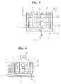
- Figs. 3 and 4 show a mono-block control valve in accordance with an embodiment of the present invention.
- a plurality of sections S1, S2 and S3 are formed in a single valve body B, which is a casted body.
- the sections S1, S2 and S3 correspond to control valves for supplying the pressurized oil of a hydraulic pump P to their associated actuators.
- One actuator A2 is shown in Fig. 4.
- the valve body B also includes a parallel passage 2 for supplying the pressurized oil of the pump P to the sections S1, S2 and S3 in parallel.
- the passage 2 is formed in the body D such that the passage 2 passes the centers of all the sections S1, S2 and S3.
- Left and right actuator ports 3 and 3' are formed in the valve body B at the opposite sides of the parallel passage 2.
- the pressurized oil of the parallel passage 2 is supplied to an associated actuator A2 through an associated actuator port, for example the port 3.
- the oil coming out of the actuator A2 is returned to the return tank T through the other actuator port 3'.
- Return passages 4 and 4' are formed in the valve body B at the outside of the actuator ports 3 and 3' respectively.
- the return passages 4 and 4' extend to the return tank T after passing through the sections S1, S2 and S3.
- the valve body B also includes a side bypass passage 1 which is formed in the outermost portion of either side of the body B.
- the side bypass passage 1 is formed in the body 1 at the outside of either return passage 4 or 4'.
- the side bypass passage 1 of this invention is formed in the body B such that the passage 1 passes all the sections S1, S2 and S3.
- the side bypass passage 1 transmits the pressurized oil of the pump P to a next section, for example S2.
- the side bypass passage 1 returns the pressurized oil to the return tank T without resistance.
- the side bypass passage 1 When at least one of the spools of the sections S1, S2 and S3 moves, the side bypass passage 1 will be shut down in that section. In this case, the pressurized oil is transmitted to either actuator port 3 or 3' through the parallel passage 2 of the section whose spool moves.
- the side bypass passage 1 is formed in the body B such that the passage 1 passes zigzag through the sections S1, S2 and S3 as best sen in Fig. 3.
- the pressurized oil delivered from the pump P is supplied to the parallel passage 2 and to the bypass passage 1.
- the pressurized oil of both the side bypass passage 1 and parallel passage 2 is returned to the return tank T after passing through the sections S1, S2 and S3.
- the pressurized oil of the parallel passage 2 of the section S2 is supplied to an associated actuator A2 through one of the actuator ports, for example the port 3. The oil in turn comes out of the actuator A2 through the other actuator port 3'.
- the prior art center bypass passage is substituted with the side bypass passage. Therefore, the valve body of this control valve does not need to have a bridge which is used for connecting the parallel passage to the left and right actuator ports while getting out of the center bypass passage.
- the passage structure of the valve body can be remarkably simplified.
- the typical three-dimensional passage structure of the valve body can be preferably submitted with a two-dimensional passage structure. The number of the passages of the valve body can be remarkably reduced, the mono-block control valve of this invention remarkably simplifies its construction and cuts down the production cost.
- the size of the valve body that is, the body height
- the space efficiency of the valve body can be thus improved.
- the surplus space defined in the valve body because of removing the bridge can be used for varieties of uses.
- Figs. 5 and 6 shows a mono-block control valve in accordance with another embodiment of the present invention.
- the left and right return passages 4 and 4' are connected together using the surplus space defined in the valve body because of removing the bridge from the valve body.
- a plurality of sections S1 and S2, corresponding to control valves for supplying the pressurized oil of the hydraulic pump P to their associated actuators, are formed in the single valve body B, which is a casted body.
- the valve body B also includes a parallel passage 2 for supplying the pressurized oil of the pump P to the sections S1 and S2 in parallel.
- the passage 2 is formed in the body D such that the passage 2 passes the centers of the sections S1 and S2.
- Left and right actuator ports 3 and 3' are formed in the valve body B at the opposite sides of the parallel passage 2.
- left and right return passages 4 and 4' are formed in the valve body B at the outside of the actuator ports 3 and 3' respectively.
- the return passages 4 and 4' extend to the return tank T after passing through the sections S1 and S2.
- the left and right return passages 4 and 4' are connected together at every section by means of a connection passage 5.
- the left and right return passages 4 and 4' are connected together at every section S1, S2 by means of the connection passage 5 using the surplus space defined in the valve body B due to the side bypass passage 1 substituting for the prior art center bypass passage.
- the passage lengths from the actuator ports 3 and 3' of each section to the return tank T are remarkably reduced.
- the control valve of this embodiment thus reduces both the passage resistance and the pressure loss.
- the passage lengths from the actuator ports 3 and 3' to the tank T of this embodiment are nearly equal to each other. Hence, there is no difference of negative pressure between the two actuator ports 3 and 3'.
- Another advantage of this embodiment is resided in that there is no section having a remarkably longer return passage than the other sections. In this regard, the difference of negative pressure between the sections can be almost completely removed.
- the mono-block control valve of this invention has the side bypass passage, substituting for the typical center bypass passage, and removes the typical bridge from the valve body, thus to simplify the passage structure in the valve body and reduce the valve body size.
- the above control valve thus improves the space efficiency and cuts down the production cost and provides a surplus space which can be used for varieties of uses.
- the left and right return passages of this control valve are connected together at every section by means of a connection passage using the surplus space. Both the passage resistance and the pressure loss in each return passage can be thus remarkably reduced.
- the connection passages also make both the negative pressures in the left and right actuator ports and the negative pressures in the sections almost completely equal to each other. Therefore, the control valve of this invention remarkably improves the operational stability and reliability.
Landscapes
- Engineering & Computer Science (AREA)
- Physics & Mathematics (AREA)
- Fluid Mechanics (AREA)
- Mechanical Engineering (AREA)
- General Engineering & Computer Science (AREA)
- Fluid-Pressure Circuits (AREA)
- Valve Housings (AREA)
Applications Claiming Priority (4)
| Application Number | Priority Date | Filing Date | Title |
|---|---|---|---|
| KR19940024400 | 1994-09-28 | ||
| KR9424400 | 1994-09-28 | ||
| KR19940024709 | 1994-09-29 | ||
| KR9424709 | 1994-09-29 |
Publications (1)
| Publication Number | Publication Date |
|---|---|
| EP0704631A1 true EP0704631A1 (de) | 1996-04-03 |
Family
ID=26630581
Family Applications (1)
| Application Number | Title | Priority Date | Filing Date |
|---|---|---|---|
| EP19950630075 Withdrawn EP0704631A1 (de) | 1994-09-28 | 1995-07-11 | Wegeventil in Mono-Blockbauweise mit seitlicher Bypassleitung |
Country Status (3)
| Country | Link |
|---|---|
| US (1) | US5586577A (de) |
| EP (1) | EP0704631A1 (de) |
| JP (1) | JPH08105404A (de) |
Families Citing this family (5)
| Publication number | Priority date | Publication date | Assignee | Title |
|---|---|---|---|---|
| US6964281B2 (en) * | 2003-02-07 | 2005-11-15 | Husco International Inc. | Multiple hydraulic spool valve assembly with a monolithic body |
| JP5778086B2 (ja) | 2012-06-15 | 2015-09-16 | 住友建機株式会社 | 建設機械の油圧回路及びその制御装置 |
| JP5978056B2 (ja) * | 2012-08-07 | 2016-08-24 | 住友建機株式会社 | 建設機械の油圧回路及びその制御装置 |
| JP6643913B2 (ja) * | 2016-02-16 | 2020-02-12 | 株式会社クボタ | 油圧ブロック |
| WO2017164169A1 (ja) * | 2016-03-22 | 2017-09-28 | 住友建機株式会社 | ショベル及びショベル用コントロールバルブ |
Citations (6)
| Publication number | Priority date | Publication date | Assignee | Title |
|---|---|---|---|---|
| GB936104A (en) * | 1960-07-21 | 1963-09-04 | Hydraulic Unit Specialities Co | Improvements in or relating to hydraulic fluid control valves |
| DE1173751B (de) * | 1961-08-14 | 1964-07-09 | Kaemper Maschb G M B H | Steuereinrichtung fuer vorzugsweise mehrere von einer Pumpe versorgte hydraulische Antriebe |
| DE1550324A1 (de) * | 1966-12-03 | 1969-04-10 | Baumgarten Hydrotech | Steuereinrichtung fuer vorzugsweise mehrere von einer Pumpe versorgte hydraulische Antriebe |
| US3970108A (en) * | 1973-10-23 | 1976-07-20 | Cross Manufacturing, Inc. | Priority hydraulic control valve |
| US4167197A (en) * | 1970-10-20 | 1979-09-11 | Toshio Maki | Directional change-over valve |
| US4256142A (en) * | 1979-08-20 | 1981-03-17 | Hancock Leonard H | Hydraulic control |
Family Cites Families (4)
| Publication number | Priority date | Publication date | Assignee | Title |
|---|---|---|---|---|
| FR1129777A (fr) * | 1955-08-12 | 1957-01-25 | Dowty Hydraulic Units Ltd | Appareil hydraulique de commande |
| DE2601484C2 (de) * | 1976-01-16 | 1984-07-26 | Robert Bosch Gmbh, 7000 Stuttgart | Steuereinrichtung für mindestens zwei von einer Druckmittelquelle gespeiste hydraulische Verbraucher |
| US4099541A (en) * | 1976-11-12 | 1978-07-11 | Sperry Rand Corporation | Power transmission |
| DE2701509C2 (de) * | 1977-01-15 | 1985-10-31 | Robert Bosch Gmbh, 7000 Stuttgart | Hydraulische Steuereinrichtung für wenigstens zwei hydraulische Verbraucher |
-
1995
- 1995-06-30 US US08/497,628 patent/US5586577A/en not_active Expired - Fee Related
- 1995-06-30 JP JP18835995A patent/JPH08105404A/ja active Pending
- 1995-07-11 EP EP19950630075 patent/EP0704631A1/de not_active Withdrawn
Patent Citations (6)
| Publication number | Priority date | Publication date | Assignee | Title |
|---|---|---|---|---|
| GB936104A (en) * | 1960-07-21 | 1963-09-04 | Hydraulic Unit Specialities Co | Improvements in or relating to hydraulic fluid control valves |
| DE1173751B (de) * | 1961-08-14 | 1964-07-09 | Kaemper Maschb G M B H | Steuereinrichtung fuer vorzugsweise mehrere von einer Pumpe versorgte hydraulische Antriebe |
| DE1550324A1 (de) * | 1966-12-03 | 1969-04-10 | Baumgarten Hydrotech | Steuereinrichtung fuer vorzugsweise mehrere von einer Pumpe versorgte hydraulische Antriebe |
| US4167197A (en) * | 1970-10-20 | 1979-09-11 | Toshio Maki | Directional change-over valve |
| US3970108A (en) * | 1973-10-23 | 1976-07-20 | Cross Manufacturing, Inc. | Priority hydraulic control valve |
| US4256142A (en) * | 1979-08-20 | 1981-03-17 | Hancock Leonard H | Hydraulic control |
Also Published As
| Publication number | Publication date |
|---|---|
| US5586577A (en) | 1996-12-24 |
| JPH08105404A (ja) | 1996-04-23 |
Similar Documents
| Publication | Publication Date | Title |
|---|---|---|
| US4170214A (en) | Hydraulic valve module | |
| EP1450049B1 (de) | Anordnung mit mehreren in einem einstückigen Gehäuse eingebrachten Schieberventile | |
| US20100300552A1 (en) | Hydraulic valve device | |
| CN113994104B (zh) | 液压控制块和带有控制块的液压轴 | |
| JPH0444881Y2 (de) | ||
| US5586577A (en) | Mono-block control valve with side bypass passage | |
| JP4170493B2 (ja) | 多連方向切換弁 | |
| US4745844A (en) | Control block comprising a plurality of valve units for a plurality of hydraulic drives, in particular fork lift trucks | |
| JP2000266002A (ja) | 油圧制御装置 | |
| EP0943813B2 (de) | Wechselventilblock | |
| EP0704629A2 (de) | Monoblock-Regelventil mit Regenerationsleitung | |
| JP2544786Y2 (ja) | 操作弁装置 | |
| JPS6138204A (ja) | 多連油圧切換弁のための多連パイロツト弁 | |
| JPH03219102A (ja) | スタック型油圧制御弁装置 | |
| WO1990011464A1 (fr) | Soupape et appareil de commande hydraulique | |
| JP2731099B2 (ja) | 油圧式クレーンの切換弁装置 | |
| CN106468293A (zh) | 阀组组件 | |
| JPH0514001Y2 (de) | ||
| JPH0658444A (ja) | 方向制御弁 | |
| JP4130256B2 (ja) | 多連方向切換弁 | |
| JP2002048105A (ja) | シリンダ装置 | |
| JP2006009940A (ja) | 方向切換弁 | |
| JPH0740780Y2 (ja) | 多連セレクタバルブ | |
| JP2000161303A (ja) | 液圧回路 | |
| JPH0633010Y2 (ja) | 油圧ショベルの油圧回路 |
Legal Events
| Date | Code | Title | Description |
|---|---|---|---|
| PUAI | Public reference made under article 153(3) epc to a published international application that has entered the european phase |
Free format text: ORIGINAL CODE: 0009012 |
|
| AK | Designated contracting states |
Kind code of ref document: A1 Designated state(s): DE FR GB IT |
|
| 17P | Request for examination filed |
Effective date: 19960517 |
|
| 17Q | First examination report despatched |
Effective date: 19980218 |
|
| RAP1 | Party data changed (applicant data changed or rights of an application transferred) |
Owner name: VOLVO CONSTRUCTION EQUIPMENT KOREA CO., LTD. |
|
| STAA | Information on the status of an ep patent application or granted ep patent |
Free format text: STATUS: THE APPLICATION IS DEEMED TO BE WITHDRAWN |
|
| 18D | Application deemed to be withdrawn |
Effective date: 19990126 |