EP0704818B1 - Xerographischer Drucker mit Tonersparmoden - Google Patents
Xerographischer Drucker mit Tonersparmoden Download PDFInfo
- Publication number
- EP0704818B1 EP0704818B1 EP95305624A EP95305624A EP0704818B1 EP 0704818 B1 EP0704818 B1 EP 0704818B1 EP 95305624 A EP95305624 A EP 95305624A EP 95305624 A EP95305624 A EP 95305624A EP 0704818 B1 EP0704818 B1 EP 0704818B1
- Authority
- EP
- European Patent Office
- Prior art keywords
- dot
- toner
- mode
- circuit
- pulse
- Prior art date
- Legal status (The legal status is an assumption and is not a legal conclusion. Google has not performed a legal analysis and makes no representation as to the accuracy of the status listed.)
- Expired - Lifetime
Links
Images

Classifications
-
- G—PHYSICS
- G06—COMPUTING OR CALCULATING; COUNTING
- G06K—GRAPHICAL DATA READING; PRESENTATION OF DATA; RECORD CARRIERS; HANDLING RECORD CARRIERS
- G06K15/00—Arrangements for producing a permanent visual presentation of the output data, e.g. computer output printers
- G06K15/02—Arrangements for producing a permanent visual presentation of the output data, e.g. computer output printers using printers
- G06K15/12—Arrangements for producing a permanent visual presentation of the output data, e.g. computer output printers using printers by photographic printing, e.g. by laser printers
- G06K15/1204—Arrangements for producing a permanent visual presentation of the output data, e.g. computer output printers using printers by photographic printing, e.g. by laser printers involving the fast moving of an optical beam in the main scanning direction
- G06K15/1209—Intensity control of the optical beam
Definitions
- the present invention relates to an electrophotographic type printer using toners, and more particularly, to such printer capable of economizing toner consumption amount.
- Japanese Patent Application Kokai No. Hei 1-133075 upon which the precharacterising portion of appended claim 1 is based discloses a laser printer having two laser diode drive sources for ordinary toner consumption mode and for toner economizing mode. If the toner economizing mode is selected, the laser diode drive source is switched to reduce the laser diode driving current so as to reduce luminous intensity of the laser diode, to thereby reduce a developing area or width per one dot of the laser beam, to thus restrain the toner consumption amount.
- laser diode driving current is controlled in an analog manner by switching the laser diode drive sources from one to another, and therefore, a great numbers of the laser diode driving sources are required if multi-stage control is intended. As a result, production cost may be increased and fine control may become difficult.
- an electrophotographic type printer using toner for printing a toner image onto a sheet comprising:
- the modulation circuit includes a shift register for delaying by a predetermined period the dot pulses generated from the pulse generating circuit if the toner economizing mode is selected by the mode selection means, and an AND gate circuit connected to the shift register for outputting a logical product of the dot pulses generated from the pulse generating circuit and the dot pulses delayed by the predetermined period by the shift register.
- an electrophotographic type printer using toner for printing a toner image onto a sheet comprising mode selection means for selectively setting one of ordinary toner consumption mode and a toner economizing mode, image buffer means for storing as dot data an image to be printed, pulse generating means for generating dot pulses indicative of ON and OFF of each dot in accordance with the dot data stored in the image buffer means, modulation means connected to the pulse generating means for modulating the dot pulses generated from the pulse generating means and for outputting the modulated dot pulses in accordance with a mode selected by the mode selection means, and print processing means for performing printing process in accordance with the modulated dot pulses outputted from the modulation means.
- dot pulses indicative of ON and OFF of each dot are generated in the pulse generating circuit in accordance with the dot data stored in the image buffer. If the toner economizing mode is selected in the mode selection switch, the modulating circuit modulates the dot pulses in such a manner that each ON width of the pulse becomes narrow. Print processing is carried out based on the modulated dot pulses.
- the dot pulses is delayed by a predetermined period by the shift register.
- the AND gate circuit then outputs a logical product of the dot pulses from the pulse generating circuit and the dot pulses delayed by the predetermined period. Accordingly, ON width of each dot pulse can be narrow, to reduce toner consumption amount.
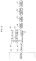
- Fig. 1 shows a laser printer 1 having a main frame 2 in which are disposed a recording process unit 3, a fixing unit 4, and a laser scanner unit 5.
- a sheet cassette 6 is detachably provided onto an upper portion of the main frame 2.
- a sheet discharge tray 7 is provided at the front portion of the main frame 2.
- the recording process unit 3 includes a photosensitive drum 8, a transfer roller 9 and a charger 10 positioned in confrontation with the photosensitive drum 8 for charging the same.
- the fixing unit 4 includes a heat roller 11 and a pressure roller 12.
- the laser scanner unit 5 includes a laser diode 30, a scanner motor 13, a lens 14, and a reflection mirror 15.
- a developing device 16 is provided in the vicinity of the recording processing unit 3.
- the developing device 16 includes a developing roller 17 positioned in confrontation with the photosensitive drum 8. Further, a toner cartridge 18 is provided which accumulates therein toners for supplying the toner to the developing roller 17.
- a sheet supply roller 19, a separation pad 20, a pair of feed rollers 21, and a pair of discharge roller 22 are provided along a sheet passage on which a sheet P supplied from the sheet cassette 6 runs.
- a power source unit 23, a control circuit board 24 and a laser driving circuit board 25, etc., are provided in the main frame 2.
- the main frame 2 has an upper surface on which a front panel or an operation panel 26 is provided.
- the front panel 26 is provided with various switches including a toner save mode selection switch 54 described later.
- the sheet P in the sheet cassette 6 is supplied to the sheet supply roller 19 and is fed to a position between the photosensitive drum 8 and the transfer roller 9 by the sheet feed rollers 21.
- the laser scanner unit 5 irradiates laser beam B to the photosensitive drum 8 from the laser diode 30 by way of the lens 14 and the reflection mirror 15 in accordance with image data transmitted from a personal computer (see Fig. 2).
- an electrostatic latent image is formed on the photosensitive drum 8.
- the latent image is converted into a toner image by the developing device 16, and the toner image is transferred onto the sheet P by the transfer roller 9.
- the image transferred to the sheet P is fixed at the fixing unit 4, and the sheet P is discharged onto the discharge tray 7 by the discharge rollers 22.
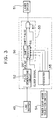
- Fig. 2 is a block diagram showing an internal electrical connection in the laser printer 1.
- a CPU 41 is adapted for controlling overall operation of the printer 1.
- a RAM 42 is adapted for temporarily storing various data for processing printing.
- a PROM 43 is adapted for storing various control programs.
- a FONTROM 44 is adapted for storing character pattern data.
- a data buffer 45 is adapted for storing image data transmitted from the personal computer 46 through an interface 47.
- An image buffer 48 is adapted for developing image data stored in the data buffer 45 into dot data with reference to the character pattern stored in the FONTROM 44, and for storing the dot data therein.
- the line buffer 49 is adapted for storing dot data which represents a single line of the sheet P, the dot data being stored in the image buffer 48.
- a save-mode circuit 50 is adapted for generating and sending dot pulse to a laser driver 51, the dot pulse being indicative of ON and OFF of each dot in accordance with the one-line dot data stored in the line buffer 49.
- Luminous control of the laser diode 30 shown in Fig. 1 is effected by the laser driver 51.
- the laser diode 30 is rendered ON upon input of high level pulse, and is rendered OFF upon input of low level pulse.
- Fig. 3 is a block diagram showing an internal arrangement of the save-mode circuit 50.
- the save mode circuit 50 includes a pulse generating circuit 52 for generating dot pulse indicative of ON and OFF of each dot in accordance with the one line dot data transmitted from the line buffer 49, a modulation circuit 53 for modulating dot pulse generated from the pulse generation circuit 52 and outputting the modulated dot pulse to the laser driver 51, and a register 55 for modulatingly controlling the modulation circuit 53 in accordance with the mode selection signal transmitted from the toner save-mode selection switch 54.
- the modulation circuit 53 includes a shift register 56 for outputting a shift pulse, and an AND gate circuit 57.
- the dot pulse from the pulse generation circuit 52 is delayed by predetermined period of time by virtue of clock pulse so as to output the shift pulse.
- the AND gate circuit 57 is adapted for outputting a logical product of the dot pulse generated form the pulse generating circuit 52 and the shift pulse delayed by a predetermined time period by the shift register 56.
- the mode selection switch 54 generally provides the ordinary toner consumption mode and the toner-save mode which includes first through fourth toner save modes.
- the mode is cyclically changed in order from one mode to the other mode in accordance with depression of the mode selection switch 54.
- the fourth toner save mode is the most toner saving mode.
- the dot pulse inputted from the pulse generating circuit 52 into the modulation circuit 53 is modulated.
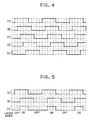
- the shift register 56 in the modulating circuit 53 can select one pulse among the five kinds of pulses shown in Fig. 4.
- (A) is the dot pulse outputted from the pulse generating circuit 52.
- (B) is a first shift pulse which is delayed or shifted by one clock from the dot pulse (A).
- (C) is a second shift pulse which is delayed by two clocks from the dot pulse (A),
- (D) is a third shift pulse which is delayed by three clocks from the dot pulse (A), and
- E) is a fourth shift pulse which is delayed by four clocks from the dot pulse (A).
- the dot pulse (A) is outputted from the shift register 56.
- the first shift pulse (B) is outputted from the shift register 56.
- the second shift pulse (C) is outputted in response to the combination of the signals of (0, 0, 1, 1)
- third shift pulse (D) is outputted in response to the signals of (0, 1, 1, 1)
- the fourth shift pulse (E) is outputted from the shift register 56 in response to the signals (1, 1, 1, 1).
- Fig. 5 shows time charts showing changes in dot pulse (a), shift pulse (b) and output pulse (c) from the AND gate circuit 57.
- the laser diode 30 In case of high level state in each pulse, the laser diode 30 emits light, and in case of low level state in each pulse, no luminous operation is performed in the laser diode 30. Accordingly, if the laser diode 30 emits light in response to the high level, the laser beam B forms the latent image on the photosensitive drum 8, and the toner image is provided by the developing device 16. That is, an image is formed on the sheet P. On the other hand, the laser beam is not provided by the laser diode 30 in response to the low level pulse, no image is formed on the sheet P.
- the dot pulses (a) indicative of ON and OFF of each dot are generated from the pulse generation circuit 52.
- the dot pulses are delayed in the shift register 56 and shift pulses (b) are outputted.
- the AND gate circuit 57 logical product of the dot pulses (a) and the shift pulses (b) is provided and the logical products (c) are outputted to the laser driver 51.
- the dot pulse (a) is outputted from the shift register 56.
- the dot pulse and the identical dot pulse is anded, and therefore, the identical dot pulse is outputted from the modulation circuit 53 to the laser driver 51.
- the second shift pulse is outputted from the shift register 56 (see (b) in Fig. 5).
- the AND gate circuit 57 the second shift pulse (b) and the dot pulse (a) is anded. Consequently, the AND output pulse (c) is outputted from the modulation circuit 53.
- the output pulses (c) from the AND gate circuit 57 is the logical product of the dot pulses (a) and the shift pulses (b), high level period in the output pulses (c) is shorter than that of the dot pulses (a). Accordingly, luminous period of the laser diode 30 is reduced, so that a spot size of the laser beam B irradiated onto the photosensitive drum 8 becomes smaller than that of the beam in the ordinary consumption mode.
- the toner are affixed to the latent imaging zone on the photosensitive drum 8, i.e., at the laser beam spot portions. Consequently, amount of toner affixed to the photosensitive drum 8 can be reduced.
- fourth toner save-mode is selected, the high level period in the output pulse (c) becomes the shortest. Accordingly, the fourth toner save mode can provide the minimized toner consumption amount.
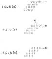
- Fig. 6(a) shows a print image according to ordinary toner consumption mode
- Fig. 6(b) shows a print image in accordance with toner economizing mode in the conventional printer according to JP'574 publication
- Fig. 6(c) shows a print image in accordance with toner economizing mode in the illustrated embodiment.
- dots 61' are omitted among the dots 61 to be printed due to the thinning out processing, and therefore, a central white-out portion may be created in the resultant image.
- Fig. 6(b) shows a print image according to ordinary toner consumption mode
- Fig. 6(b) shows a print image in accordance with toner economizing mode in the conventional printer according to JP'574 publication
- Fig. 6(c) shows a print image in accordance with toner economizing mode in the illustrated embodiment.
- dots 61' are omitted among the dots 61 to be printed due to the thinning out processing, and therefore, a central white
- toner consumption amount per one dot can be controlled and reduced, and therefore, printing quality can be maintained while economizing the toner consumption, to thus reduce running cost of the laser printer 1.
- a plurality of levels can be provided as the toner save mode. In accordance with the selected level, phase of the shift pulse outputted from the shift register 56 can be properly controlled, to thereby control delaying period of the dot pulse. Thus, multi-stage or fine control to the toner consumption can be performed.
- the manner for modulating the dot pulse transmitted from the pulse generating circuit 52 is not limited to the case where the shift register 56 and the AND gate circuit 57 are used.
- the toner mode selection is made by depression of the toner mode selection switch.
- selection of the toner consumption mode can also be made by way of a signal transmitted from a personal computer.
- dot pulses indicative of ON/OFF of each dot is modulated and printing operation is carried out based on the modulated dot pulse if the toner economizing mode is selected. Further, fine multiple stage control is achievable in digital manner with respect to the toner consumption, and toner consumption amount per one dot can be reduced. Further, thinning-out processing is not performed, so that disappearance of fine character or line does not occur. Thus, toner consumption can be economized yet maintaining a printing quality at a certain level to thereby lower the running cost.
Landscapes
- Physics & Mathematics (AREA)
- Engineering & Computer Science (AREA)
- Optics & Photonics (AREA)
- General Engineering & Computer Science (AREA)
- General Physics & Mathematics (AREA)
- Theoretical Computer Science (AREA)
- Control Or Security For Electrophotography (AREA)
- Laser Beam Printer (AREA)
- Fax Reproducing Arrangements (AREA)
- Dot-Matrix Printers And Others (AREA)
- Exposure Or Original Feeding In Electrophotography (AREA)
- Dry Development In Electrophotography (AREA)
Claims (8)
- Elektrofotografischer Drucker, der Toner benutzt, zum Drucken eines Tonerbildes auf ein Blatt, mit:gekennzeichnet durch:einem Modusauswahlschalter (54) zum selektiven Einstellen eines gewöhnlichen Tonerverbrauchsmodus und eines Tonereinsparungsmodus; undeinem Druckprozessor (51) zum Ausführen eines Druckprozesses;einen Bildpuffer (48, 49) zum Speichern eines zu druckenden Bildes als Punktdaten;eine Pulserzeugerschaltung (52) zum Erzeugen von Punktpulsen, die EIN und AUS eines jeden Punktes gemäß den in dem Bildpuffer (48, 49) gespeicherten Punktdaten bezeichnen; undeine Modulationsschaltung (50), die mit der Pulserzeugerschaltung (52) verbunden ist, zum Modulieren der Punktpulse, die von der Pulserzeugerschaltung (52) erzeugt werden, undzum Ausgeben der modulierten Punktpulse gemäß dem von dem Modusauswahlschalter (54) ausgewählten Modus, wobei die Modulationsschaltung eine Verzögerungsschaltung (56) zum Verzögern der Punktpulse, die von der Pulserzeugerschaltung (52) erzeugt sind, um eine vorbestimmte Dauer, wenn der Tonereinsparungsmodus durch den Modusauswahlschalter (54) ausgewählt ist, und eine Logikschaltung (57), die mit der Verzögerungsschaltung (56) verbunden ist, zum Ausgeben einer Logikausgabe auf der Grundlage der Punktpulse, die von der Pulserzeugerschaltung (52) erzeugt sind, und der Punktpulse, die um die vorbestimmte Dauer durch die Verzögerungsschaltung (56) verzögert sind, aufweist;worin der Druckprozessor (51) den Druckprozeß gemäß der modulierten Punktpulse ausführt, die von der Modulationsschaltung (50) ausgegeben werden.
- Elektrofotografischer Drucker nach Anspruch 1, bei dem die Verzögerungsschaltung (56) ein Schieberegister (56) aufweist und die Logikschaltung (57) eine UND-Gatterschaltung (57) aufweist, die mit dem Schieberegister (56) verbunden ist, zum Ausgeben eines logischen Produktes der Punktpulse, die von der Pulserzeugerschaltung (52) erzeugt sind, und der Punktpulse, die um die vorbestimmte Dauer durch das Schieberegister (56) verzögert sind.
- Elektrofotografischer Drucker nach Anspruch 2, bei dem der Tonereinsparungsmodus eine Mehrzahl von Tonersparmodi enthält, die eine Punktgröße unterschiedlich voneinander vorsehen, und der Drucker weiter ein Auswahlregister (55) aufweist, das mit dem Modusauswahlschalter (54) verbunden ist, zum Speichern eines des gewöhnlichen Tonereinsparungsmodus und des Tonersparmodus, die von dem Modusauswahlschalter ausgewählt sind, wobei das Auswahlregister (55) ein Signal ausgibt, das die Verzögerungsdauer des Schieberegisters (56) bezeichnet, wobei die Verzögerungsdauer dem ausgewählten Modus entspricht.
- Elektrofotografischer Drucker nach Anspruch 3, bei dem das Auswahlregister (55) mit dem Schieberegister (56) durch eine Mehrzahl von Signalleitungen verbunden ist, wobei jede Signalleitung dadurch ein Binärsignal überträgt und wobei eine Kombination von Binärsignalen den ausgewählten Modus bezeichnet.
- Elektrofotografischer Drucker nach Anspruch 2, 3 oder 4, bei dem der Druckprozessor (51) aufweist:eine Laserdiode zum Erzeugen eines Laserstrahles, die EIN und AUS gemäß einem Hochpegelsignal und einem Niederpegelsignal des logischen Produktes geschaltet wird;eine lichtempfindliche Trommel mit einer äußeren Oberfläche, auf die der Laserstrahl so gestrahlt wird, daß ein elektrostatisches latentes Bild auf der äußeren Oberfläche vorgesehen wird; undein Entwicklungsmittel zum Liefern von Toner zu der lichtempfindlichen Trommel so, daß ein Tonerbild darauf an einer Position entsprechend dem latenten Bild vorgesehen wird.
- Elektrofotografischer Drucker nach einem der Ansprüche 2 bis 5, weiter mit einer Taktsignalerzeugerschaltung, die mit dem Schieberegister (56) verbunden ist, wobei die Taktsignalerzeugerschaltung ein Taktsignal erzeugt und das Taktsignal zu dem Schieberegister (56) überträgt, indem der Punktpuls um die Zahl der Taktsignale verzögert wird.
- Elektrofotografischer Drucker nach einem der vorhergehenden Ansprüche, weiter mit einem Hauptgehäuse, dem Bildpuffer (48, 49), der Pulserzeugerschaltung (52), der Modulationsschaltung (50),und dem Druckprozessor (51), die alle in dem Hauptrahmen vorgesehen sind.
- Elektrofotografischer Drucker nach Anspruch 7, weiter mit einer Betätigungstafel, die in dem Hauptgehäuse vorgesehen ist, wobei der Modusauswahlschalter (54) an der Betätigungstafel positioniert ist.
Applications Claiming Priority (3)
| Application Number | Priority Date | Filing Date | Title |
|---|---|---|---|
| JP21186994A JP3663641B2 (ja) | 1994-08-11 | 1994-08-11 | 印字装置 |
| JP211869/94 | 1994-08-11 | ||
| JP21186994 | 1994-08-11 |
Publications (2)
| Publication Number | Publication Date |
|---|---|
| EP0704818A1 EP0704818A1 (de) | 1996-04-03 |
| EP0704818B1 true EP0704818B1 (de) | 2001-11-07 |
Family
ID=16612968
Family Applications (1)
| Application Number | Title | Priority Date | Filing Date |
|---|---|---|---|
| EP95305624A Expired - Lifetime EP0704818B1 (de) | 1994-08-11 | 1995-08-11 | Xerographischer Drucker mit Tonersparmoden |
Country Status (4)
| Country | Link |
|---|---|
| US (1) | US5583621A (de) |
| EP (1) | EP0704818B1 (de) |
| JP (1) | JP3663641B2 (de) |
| DE (1) | DE69523712T2 (de) |
Families Citing this family (18)
| Publication number | Priority date | Publication date | Assignee | Title |
|---|---|---|---|---|
| JP2959394B2 (ja) * | 1994-04-25 | 1999-10-06 | ブラザー工業株式会社 | 画像形成装置並びにファクシミリ装置 |
| JP3097450B2 (ja) * | 1994-04-25 | 2000-10-10 | ブラザー工業株式会社 | 記録装置およびファクシミリ装置 |
| US6975427B1 (en) | 2000-03-27 | 2005-12-13 | International Business Machines Corporation | Method, system, and program for using look-up tables to filter raster data |
| US6975428B1 (en) | 2000-03-27 | 2005-12-13 | International Business Machines Corporation | Method, system, and program for reducing toner usage in print output |
| US7064859B1 (en) | 2000-03-27 | 2006-06-20 | International Business Machines Corporation | Method, system, program, and data structure for producing a look-up table to enhance print quality |
| JP2002156801A (ja) * | 2000-09-06 | 2002-05-31 | Ricoh Co Ltd | 画像形成装置 |
| JP2003243714A (ja) * | 2001-12-11 | 2003-08-29 | Sharp Corp | 発光素子の駆動回路、および、それを用いる光通信デバイス |
| JP4175011B2 (ja) * | 2002-03-29 | 2008-11-05 | ブラザー工業株式会社 | 画像形成装置 |
| US6819900B2 (en) * | 2002-12-16 | 2004-11-16 | Kabushiki Kaisha Toshiba | Apparatus and method for forming image including controlling supply of new and recycled toner |
| KR100729309B1 (ko) * | 2003-05-14 | 2007-06-19 | 캐논 가부시끼가이샤 | 화상형성장치, 카트리지 및 카트리지에 장착되는 저장장치 |
| JP4439994B2 (ja) | 2003-05-14 | 2010-03-24 | キヤノン株式会社 | 画像形成装置及びカートリッジ、カートリッジに搭載される記憶装置 |
| JP4537116B2 (ja) * | 2003-05-14 | 2010-09-01 | キヤノン株式会社 | 画像形成装置及びカートリッジ、カートリッジに搭載される記憶装置 |
| KR20080006025A (ko) * | 2004-12-10 | 2008-01-15 | 가부시키가이샤 리코 | 윤활제 도포 장치 및 이를 구비하는 전사 장치, 프로세스카트리지, 화상형성장치 |
| KR100666957B1 (ko) * | 2005-05-10 | 2007-01-10 | 삼성전자주식회사 | 레이저 출력 제어장치 및 그 방법 |
| KR100712480B1 (ko) | 2005-06-15 | 2007-04-30 | 삼성전자주식회사 | 화상형성장치, 광주사장치 및 화상형성방법 |
| US8467082B1 (en) | 2010-03-23 | 2013-06-18 | Jonathan Miller | Print compound conserving font production method |
| US9036200B2 (en) | 2010-09-14 | 2015-05-19 | Hewlett-Packard Development Company, L.P. | Job processing by dividing a job into sub-jobs for rendering and streaming |
| US9311027B2 (en) | 2013-03-28 | 2016-04-12 | Hewlett-Packard Development Company, L.P. | Document generation based on target device availability |
Family Cites Families (6)
| Publication number | Priority date | Publication date | Assignee | Title |
|---|---|---|---|---|
| JP2505226B2 (ja) * | 1987-11-18 | 1996-06-05 | ミノルタ株式会社 | レ―ザビ―ム露光方式の電子写真装置 |
| JPH02144574A (ja) * | 1988-11-25 | 1990-06-04 | Toshiba Corp | 電子写真方式のプリンタ装置 |
| JPH03126053A (ja) * | 1989-10-12 | 1991-05-29 | Ricoh Co Ltd | 画像形成装置 |
| JPH03268563A (ja) * | 1990-03-16 | 1991-11-29 | Mita Ind Co Ltd | レーザビーム制御装置 |
| JPH0614167A (ja) * | 1992-06-26 | 1994-01-21 | Canon Inc | 電子写真方式のプリンタ |
| JPH0698126A (ja) * | 1992-09-10 | 1994-04-08 | Toshiba Corp | ファクシミリ装置 |
-
1994
- 1994-08-11 JP JP21186994A patent/JP3663641B2/ja not_active Expired - Fee Related
-
1995
- 1995-07-31 US US08/509,608 patent/US5583621A/en not_active Expired - Lifetime
- 1995-08-11 EP EP95305624A patent/EP0704818B1/de not_active Expired - Lifetime
- 1995-08-11 DE DE69523712T patent/DE69523712T2/de not_active Expired - Lifetime
Also Published As
| Publication number | Publication date |
|---|---|
| US5583621A (en) | 1996-12-10 |
| DE69523712T2 (de) | 2002-05-08 |
| JP3663641B2 (ja) | 2005-06-22 |
| DE69523712D1 (de) | 2001-12-13 |
| EP0704818A1 (de) | 1996-04-03 |
| JPH0854806A (ja) | 1996-02-27 |
Similar Documents
| Publication | Publication Date | Title |
|---|---|---|
| EP0704818B1 (de) | Xerographischer Drucker mit Tonersparmoden | |
| US5355200A (en) | Printer with print density switching means | |
| US5187495A (en) | Image forming apparatus for obtaining image upon scanning with laser beam | |
| US5436647A (en) | Color image forming apparatus | |
| US7949266B2 (en) | Image forming apparatus with function of toner supply amount control | |
| US5159357A (en) | Non-impact printer for recording in color | |
| JPH10319789A (ja) | 電子写真式画像形成装置 | |
| US5361088A (en) | Electrophotographic printer and method for controlling the same | |
| JP3227316B2 (ja) | 電子写真装置 | |
| US5448278A (en) | Image forming apparatus using variable light beam | |
| JPH0772678A (ja) | 画像記録装置 | |
| US5198841A (en) | Electric printer | |
| US20030063184A1 (en) | Method and apparatus for controlling a light signal in electrophotographic recording apparatus | |
| JPH07266615A (ja) | 電子写真装置 | |
| JPH04249182A (ja) | レーザビームプリンタ | |
| JP2002351187A (ja) | 印刷処理装置および印刷処理方法 | |
| JP2538763B2 (ja) | 電子写真式プリンタ | |
| JPH10193684A (ja) | Led書き込み装置 | |
| JP2004098472A (ja) | 画像形成装置 | |
| JPH04296782A (ja) | トナー補給制御方法及びその方法を用いた画像形成装置 | |
| JP4616365B2 (ja) | 画像形成装置 | |
| JP3036547B2 (ja) | プリンタ | |
| JP3124015B2 (ja) | 画像形成装置 | |
| JPH1138838A (ja) | 記録装置、記録制御システム、ならびに記録制御方法 | |
| JP2007007935A (ja) | 画像形成装置、および画像形成装置の制御方法 |
Legal Events
| Date | Code | Title | Description |
|---|---|---|---|
| PUAI | Public reference made under article 153(3) epc to a published international application that has entered the european phase |
Free format text: ORIGINAL CODE: 0009012 |
|
| AK | Designated contracting states |
Kind code of ref document: A1 Designated state(s): DE FR GB |
|
| 17P | Request for examination filed |
Effective date: 19960524 |
|
| 17Q | First examination report despatched |
Effective date: 19990701 |
|
| GRAG | Despatch of communication of intention to grant |
Free format text: ORIGINAL CODE: EPIDOS AGRA |
|
| GRAG | Despatch of communication of intention to grant |
Free format text: ORIGINAL CODE: EPIDOS AGRA |
|
| GRAH | Despatch of communication of intention to grant a patent |
Free format text: ORIGINAL CODE: EPIDOS IGRA |
|
| GRAH | Despatch of communication of intention to grant a patent |
Free format text: ORIGINAL CODE: EPIDOS IGRA |
|
| GRAA | (expected) grant |
Free format text: ORIGINAL CODE: 0009210 |
|
| AK | Designated contracting states |
Kind code of ref document: B1 Designated state(s): DE FR GB |
|
| REF | Corresponds to: |
Ref document number: 69523712 Country of ref document: DE Date of ref document: 20011213 |
|
| REG | Reference to a national code |
Ref country code: GB Ref legal event code: IF02 |
|
| ET | Fr: translation filed | ||
| PLBE | No opposition filed within time limit |
Free format text: ORIGINAL CODE: 0009261 |
|
| STAA | Information on the status of an ep patent application or granted ep patent |
Free format text: STATUS: NO OPPOSITION FILED WITHIN TIME LIMIT |
|
| 26N | No opposition filed | ||
| PGFP | Annual fee paid to national office [announced via postgrant information from national office to epo] |
Ref country code: DE Payment date: 20140901 Year of fee payment: 20 |
|
| PGFP | Annual fee paid to national office [announced via postgrant information from national office to epo] |
Ref country code: FR Payment date: 20140725 Year of fee payment: 20 Ref country code: GB Payment date: 20140725 Year of fee payment: 20 |
|
| REG | Reference to a national code |
Ref country code: DE Ref legal event code: R071 Ref document number: 69523712 Country of ref document: DE |
|
| REG | Reference to a national code |
Ref country code: GB Ref legal event code: PE20 Expiry date: 20150810 |
|
| PG25 | Lapsed in a contracting state [announced via postgrant information from national office to epo] |
Ref country code: GB Free format text: LAPSE BECAUSE OF EXPIRATION OF PROTECTION Effective date: 20150810 |