EP0705955A1 - Elektrischer oder pneumatischer Türantrieb - Google Patents
Elektrischer oder pneumatischer Türantrieb Download PDFInfo
- Publication number
- EP0705955A1 EP0705955A1 EP95890175A EP95890175A EP0705955A1 EP 0705955 A1 EP0705955 A1 EP 0705955A1 EP 95890175 A EP95890175 A EP 95890175A EP 95890175 A EP95890175 A EP 95890175A EP 0705955 A1 EP0705955 A1 EP 0705955A1
- Authority
- EP
- European Patent Office
- Prior art keywords
- door
- drive
- self
- locking
- closing
- Prior art date
- Legal status (The legal status is an assumption and is not a legal conclusion. Google has not performed a legal analysis and makes no representation as to the accuracy of the status listed.)
- Withdrawn
Links
Images


Classifications
-
- E—FIXED CONSTRUCTIONS
- E05—LOCKS; KEYS; WINDOW OR DOOR FITTINGS; SAFES
- E05F—DEVICES FOR MOVING WINGS INTO OPEN OR CLOSED POSITION; CHECKS FOR WINGS; WING FITTINGS NOT OTHERWISE PROVIDED FOR, CONCERNED WITH THE FUNCTIONING OF THE WING
- E05F15/00—Power-operated mechanisms for wings
- E05F15/60—Power-operated mechanisms for wings using electrical actuators
- E05F15/603—Power-operated mechanisms for wings using electrical actuators using rotary electromotors
- E05F15/632—Power-operated mechanisms for wings using electrical actuators using rotary electromotors for horizontally-sliding wings
- E05F15/649—Power-operated mechanisms for wings using electrical actuators using rotary electromotors for horizontally-sliding wings operated by swinging arms
-
- E—FIXED CONSTRUCTIONS
- E05—LOCKS; KEYS; WINDOW OR DOOR FITTINGS; SAFES
- E05F—DEVICES FOR MOVING WINGS INTO OPEN OR CLOSED POSITION; CHECKS FOR WINGS; WING FITTINGS NOT OTHERWISE PROVIDED FOR, CONCERNED WITH THE FUNCTIONING OF THE WING
- E05F15/00—Power-operated mechanisms for wings
- E05F15/50—Power-operated mechanisms for wings using fluid-pressure actuators
- E05F15/53—Power-operated mechanisms for wings using fluid-pressure actuators for swinging wings
-
- E—FIXED CONSTRUCTIONS
- E05—LOCKS; KEYS; WINDOW OR DOOR FITTINGS; SAFES
- E05F—DEVICES FOR MOVING WINGS INTO OPEN OR CLOSED POSITION; CHECKS FOR WINGS; WING FITTINGS NOT OTHERWISE PROVIDED FOR, CONCERNED WITH THE FUNCTIONING OF THE WING
- E05F11/00—Man-operated mechanisms for operating wings, including those which also operate the fastening
- E05F11/54—Man-operated mechanisms for operating wings, including those which also operate the fastening for doors
-
- E—FIXED CONSTRUCTIONS
- E05—LOCKS; KEYS; WINDOW OR DOOR FITTINGS; SAFES
- E05Y—INDEXING SCHEME ASSOCIATED WITH SUBCLASSES E05D AND E05F, RELATING TO CONSTRUCTION ELEMENTS, ELECTRIC CONTROL, POWER SUPPLY, POWER SIGNAL OR TRANSMISSION, USER INTERFACES, MOUNTING OR COUPLING, DETAILS, ACCESSORIES, AUXILIARY OPERATIONS NOT OTHERWISE PROVIDED FOR, APPLICATION THEREOF
- E05Y2201/00—Constructional elements; Accessories therefor
- E05Y2201/20—Brakes; Disengaging means; Holders; Stops; Valves; Accessories therefor
- E05Y2201/214—Disengaging means
-
- E—FIXED CONSTRUCTIONS
- E05—LOCKS; KEYS; WINDOW OR DOOR FITTINGS; SAFES
- E05Y—INDEXING SCHEME ASSOCIATED WITH SUBCLASSES E05D AND E05F, RELATING TO CONSTRUCTION ELEMENTS, ELECTRIC CONTROL, POWER SUPPLY, POWER SIGNAL OR TRANSMISSION, USER INTERFACES, MOUNTING OR COUPLING, DETAILS, ACCESSORIES, AUXILIARY OPERATIONS NOT OTHERWISE PROVIDED FOR, APPLICATION THEREOF
- E05Y2201/00—Constructional elements; Accessories therefor
- E05Y2201/20—Brakes; Disengaging means; Holders; Stops; Valves; Accessories therefor
- E05Y2201/218—Holders
- E05Y2201/22—Locks
-
- E—FIXED CONSTRUCTIONS
- E05—LOCKS; KEYS; WINDOW OR DOOR FITTINGS; SAFES
- E05Y—INDEXING SCHEME ASSOCIATED WITH SUBCLASSES E05D AND E05F, RELATING TO CONSTRUCTION ELEMENTS, ELECTRIC CONTROL, POWER SUPPLY, POWER SIGNAL OR TRANSMISSION, USER INTERFACES, MOUNTING OR COUPLING, DETAILS, ACCESSORIES, AUXILIARY OPERATIONS NOT OTHERWISE PROVIDED FOR, APPLICATION THEREOF
- E05Y2201/00—Constructional elements; Accessories therefor
- E05Y2201/20—Brakes; Disengaging means; Holders; Stops; Valves; Accessories therefor
- E05Y2201/23—Actuation thereof
- E05Y2201/232—Actuation thereof by automatically acting means
-
- E—FIXED CONSTRUCTIONS
- E05—LOCKS; KEYS; WINDOW OR DOOR FITTINGS; SAFES
- E05Y—INDEXING SCHEME ASSOCIATED WITH SUBCLASSES E05D AND E05F, RELATING TO CONSTRUCTION ELEMENTS, ELECTRIC CONTROL, POWER SUPPLY, POWER SIGNAL OR TRANSMISSION, USER INTERFACES, MOUNTING OR COUPLING, DETAILS, ACCESSORIES, AUXILIARY OPERATIONS NOT OTHERWISE PROVIDED FOR, APPLICATION THEREOF
- E05Y2201/00—Constructional elements; Accessories therefor
- E05Y2201/40—Motors; Magnets; Springs; Weights; Accessories therefor
- E05Y2201/43—Motors
- E05Y2201/434—Electromotors; Details thereof
-
- E—FIXED CONSTRUCTIONS
- E05—LOCKS; KEYS; WINDOW OR DOOR FITTINGS; SAFES
- E05Y—INDEXING SCHEME ASSOCIATED WITH SUBCLASSES E05D AND E05F, RELATING TO CONSTRUCTION ELEMENTS, ELECTRIC CONTROL, POWER SUPPLY, POWER SIGNAL OR TRANSMISSION, USER INTERFACES, MOUNTING OR COUPLING, DETAILS, ACCESSORIES, AUXILIARY OPERATIONS NOT OTHERWISE PROVIDED FOR, APPLICATION THEREOF
- E05Y2201/00—Constructional elements; Accessories therefor
- E05Y2201/60—Suspension or transmission members; Accessories therefor
- E05Y2201/622—Suspension or transmission members elements
- E05Y2201/676—Transmission of human force
-
- E—FIXED CONSTRUCTIONS
- E05—LOCKS; KEYS; WINDOW OR DOOR FITTINGS; SAFES
- E05Y—INDEXING SCHEME ASSOCIATED WITH SUBCLASSES E05D AND E05F, RELATING TO CONSTRUCTION ELEMENTS, ELECTRIC CONTROL, POWER SUPPLY, POWER SIGNAL OR TRANSMISSION, USER INTERFACES, MOUNTING OR COUPLING, DETAILS, ACCESSORIES, AUXILIARY OPERATIONS NOT OTHERWISE PROVIDED FOR, APPLICATION THEREOF
- E05Y2400/00—Electronic control; Electrical power; Power supply; Power or signal transmission; User interfaces
- E05Y2400/10—Electronic control
- E05Y2400/30—Electronic control of motors
- E05Y2400/3013—Electronic control of motors during manual wing operation
- E05Y2400/3017—Safety means therefor
-
- E—FIXED CONSTRUCTIONS
- E05—LOCKS; KEYS; WINDOW OR DOOR FITTINGS; SAFES
- E05Y—INDEXING SCHEME ASSOCIATED WITH SUBCLASSES E05D AND E05F, RELATING TO CONSTRUCTION ELEMENTS, ELECTRIC CONTROL, POWER SUPPLY, POWER SIGNAL OR TRANSMISSION, USER INTERFACES, MOUNTING OR COUPLING, DETAILS, ACCESSORIES, AUXILIARY OPERATIONS NOT OTHERWISE PROVIDED FOR, APPLICATION THEREOF
- E05Y2800/00—Details, accessories and auxiliary operations not otherwise provided for
- E05Y2800/25—Emergency conditions
-
- E—FIXED CONSTRUCTIONS
- E05—LOCKS; KEYS; WINDOW OR DOOR FITTINGS; SAFES
- E05Y—INDEXING SCHEME ASSOCIATED WITH SUBCLASSES E05D AND E05F, RELATING TO CONSTRUCTION ELEMENTS, ELECTRIC CONTROL, POWER SUPPLY, POWER SIGNAL OR TRANSMISSION, USER INTERFACES, MOUNTING OR COUPLING, DETAILS, ACCESSORIES, AUXILIARY OPERATIONS NOT OTHERWISE PROVIDED FOR, APPLICATION THEREOF
- E05Y2900/00—Application of doors, windows, wings or fittings thereof
- E05Y2900/50—Application of doors, windows, wings or fittings thereof for vehicles
- E05Y2900/51—Application of doors, windows, wings or fittings thereof for vehicles for railway cars or mass transit vehicles
Definitions
- the invention relates to an electric or pneumatic door drive, in particular for vehicle doors, which is designed to be self-locking in the closed position of the door.
- Such drives are frequently used and are designed to be self-locking in the area of the closing end position of the door, since after the door is closed the electric drive is switched off or the pressure in the pneumatic cylinder is not maintained or would not be sufficient in itself to forcefully open the door To prevent door.
- the self-locking which can be a dead center mechanism or an over dead center mechanism (toggle lever), prevents the door from being opened by vibrations and / or manipulations on the door leaf.
- the self-locking mechanism is designed in such a way that no amount of force applied to the door will lead to its opening.
- This document relates to an emergency actuation device for a generic door, whereby to facilitate emergency actuation a slider acting in the opening direction of the door is provided which is held by a holding device which can be released by hand. This document solves the problem of opening a generic door in an emergency, but not its subsequent closing if the drive is defective.
- DE-A 36 39 177 which relates to a pneumatically or hydraulically operated door control.
- the door is released in the event of an emergency during a door movement (pinching a person or an object). This document therefore does not affect the failure of the door drive.
- DE-A 43 11 287 discloses a safety release for door leaves that can be moved overhead, in which the drive can only be uncoupled from the door leaf in predetermined door leaf positions if the drive energy fails in order to prevent the door leaf from falling. The problems underlying the invention are not affected.
- the invention has set itself the task of avoiding the disadvantages described above and to provide a device that makes it possible to reliably close a defective door in a simple and inexpensive manner and to lock it for regular operation without opening the door in an emergency is prevented.
- a manually operated emergency closing device is arranged on the door drive, by means of which if the door drive fails, the drive can be moved at least to overcome the self-locking area, since the door can be brought up to this area by hand.
- This manually operated emergency closing device can be, for example, a lever or a crank, whereby it should be borne in mind that the drive only has to be moved over short distances by this device, since the door can be closed up to the closing end position by moving the door.
- the effort in the case of a defective door drive is reduced to the fact that an authorized person closes the door to the self-locking area of the drive, then makes the final entry into the closed end position by the emergency closing device, switches off the drive to a clearly defined operating state to create and finally the door marked as broken.
- the additional lock is as superfluous as the bridging of the closing position monitor. This also eliminates the risk of activating the drive when the lock is locked.
- a door leaf 1 shows an inside view and a side view of a two-leaf electrically operated swinging door equipped according to the invention.
- a door leaf 1 can be pivoted about a vertically extending door boom tube 4 via a lower link 2 and an upper link 3.
- a guide link 5 is provided in the upper door area, which ensures that the door leaf 1 is pivoted substantially parallel to itself outwards and away from the center of the door opening.
- the actual door drive that causes this movement is located in the upper area between the door tree tubes of the two door leaves.
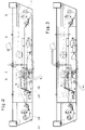
- Fig. 2 is a view in the direction of arrow II of Fig. 1 on an enlarged scale and shows the drive mechanism for the door leaves 1.
- This drive consists of a pivot lever 6 which is pivotable about a vertical axis 7 fixed to the vehicle body.
- the arm of the swivel lever 6 on the door side is connected by means of links 8 and 10 to an axle link 9, 11 which is fixedly connected to one of the two door tree tubes 4.
- the door boom tubes rotate when the swivel lever is turned.
- the pivoting lever is rotated by the engagement of a translationally moved pin 12 in a curved link 13 in the drive-side arm of the pivoting lever 6.
- the engagement conditions are shown in more detail in FIGS. 4 and 5, the position of the drive and thus of the pivoting lever 6 in each case 2 and 4 and FIGS. 3 and 5 correspond.
- FIGS. 2 and 4 corresponds to the essentially closed but not yet locked position of the door leaves 1.
- the application of a closing force in the direction of arrow S leads from the door coming and acting on the pivot lever 6, due to the shape of the link 13, there is only a slight displacement of the pin 12 along the drive effective direction 14.
- Locking mechanism in the drive train in front of the self-locking part provides.
- it is a claw 15 which can be pivoted about a vertical axis 16, the claw 15 acting in the closing direction on a drive part 17 which is operatively connected to the pin 12.
- the door closing indicator shows the properly closed position and it can be attached to the door that it is defective and is blocked for proper operation.
- the door emergency opening device or the like usually being made from a spring-loaded piston. exists, which pushes the pin 12 together with its support from the self-locking locked position and at the same time switches the door drive at a designated point without force for safety reasons.
- This can be done either by interrupting the power supply (electrical drive) or by venting a pneumatic cylinder (pneumatic drive).
- This powerless switching of the door drive usually takes place at a different location than the switching off in the event of the door drive defect, so that the two devices function completely independently of one another.
- the invention is not limited to the example shown, but can also be used for all other door drives that are designed to be self-locking in the door end closing area, ie for all door drives in which the door retracted into the closed end position by the door even when the door drive is switched off acting forces can not be opened. In all these cases, only a manually operated locking device must be provided in the door drive in the area of the power transmission in front of the self-locking component.
- a spindle with a finger similar to a horizontally arranged jack, could be provided; it would also be possible to attach a cable pull mechanism.
- the drive train is understood to mean all mechanical components that are located between the actual engine or piston and the door or the door leaf, the expressions "On the drive side” and “on the door side” are used specifically in connection with the self-locking for all the components of the drive train that are located on the corresponding side of the power flow.
- the self-locking in the example shown is the boundary between the link (on the door side) and the pin (on the drive side). Other constructions must be assessed accordingly.
Landscapes
- Power-Operated Mechanisms For Wings (AREA)
Applications Claiming Priority (2)
| Application Number | Priority Date | Filing Date | Title |
|---|---|---|---|
| AT1891/94 | 1994-10-05 | ||
| AT0189194A AT403079B (de) | 1994-10-05 | 1994-10-05 | Türantrieb |
Publications (1)
| Publication Number | Publication Date |
|---|---|
| EP0705955A1 true EP0705955A1 (de) | 1996-04-10 |
Family
ID=3523251
Family Applications (1)
| Application Number | Title | Priority Date | Filing Date |
|---|---|---|---|
| EP95890175A Withdrawn EP0705955A1 (de) | 1994-10-05 | 1995-10-04 | Elektrischer oder pneumatischer Türantrieb |
Country Status (3)
| Country | Link |
|---|---|
| EP (1) | EP0705955A1 (cs) |
| AT (1) | AT403079B (cs) |
| CZ (1) | CZ259595A3 (cs) |
Cited By (1)
| Publication number | Priority date | Publication date | Assignee | Title |
|---|---|---|---|---|
| EP0744310A1 (de) * | 1995-05-24 | 1996-11-27 | Inventio Ag | Entriegelungs- und Verriegelungseinrichtung für eine Schwenkschiebetür |
Citations (4)
| Publication number | Priority date | Publication date | Assignee | Title |
|---|---|---|---|---|
| GB2023712A (en) * | 1978-06-21 | 1980-01-03 | Tebel Maschf Bv | Vehicle door actuating mechanism |
| DE3639177A1 (de) | 1986-11-15 | 1988-05-26 | Wabco Westinghouse Fahrzeug | Tuersteuereinrichtung |
| AT391912B (de) | 1988-03-29 | 1990-12-27 | Ife Gmbh | Notbetaetigungsvorrichtung fuer eine mit einem nicht selbsthemmenden elektrischen antrieb betaetigte fahrzeugtuer |
| DE4311287A1 (de) | 1992-04-10 | 1993-10-14 | Marantec Antrieb Steuerung | Sicherheitsentriegelung für über Kopf bewegbare Torblätter |
-
1994
- 1994-10-05 AT AT0189194A patent/AT403079B/de not_active IP Right Cessation
-
1995
- 1995-10-04 EP EP95890175A patent/EP0705955A1/de not_active Withdrawn
- 1995-10-05 CZ CZ952595A patent/CZ259595A3/cs unknown
Patent Citations (4)
| Publication number | Priority date | Publication date | Assignee | Title |
|---|---|---|---|---|
| GB2023712A (en) * | 1978-06-21 | 1980-01-03 | Tebel Maschf Bv | Vehicle door actuating mechanism |
| DE3639177A1 (de) | 1986-11-15 | 1988-05-26 | Wabco Westinghouse Fahrzeug | Tuersteuereinrichtung |
| AT391912B (de) | 1988-03-29 | 1990-12-27 | Ife Gmbh | Notbetaetigungsvorrichtung fuer eine mit einem nicht selbsthemmenden elektrischen antrieb betaetigte fahrzeugtuer |
| DE4311287A1 (de) | 1992-04-10 | 1993-10-14 | Marantec Antrieb Steuerung | Sicherheitsentriegelung für über Kopf bewegbare Torblätter |
Cited By (1)
| Publication number | Priority date | Publication date | Assignee | Title |
|---|---|---|---|---|
| EP0744310A1 (de) * | 1995-05-24 | 1996-11-27 | Inventio Ag | Entriegelungs- und Verriegelungseinrichtung für eine Schwenkschiebetür |
Also Published As
| Publication number | Publication date |
|---|---|
| CZ259595A3 (en) | 1996-04-17 |
| AT403079B (de) | 1997-11-25 |
| ATA189194A (de) | 1997-03-15 |
Similar Documents
| Publication | Publication Date | Title |
|---|---|---|
| DE10020825B4 (de) | Verfahren und Vorrichtung zum Schliessen einer Tür eines Flugzeuges | |
| EP2297421B1 (de) | Türantrieb | |
| DE60107921T2 (de) | Schliessteuervorrichtung für eine Schiebetür | |
| DE19755695A1 (de) | Drehfallenschloß, insbesondere für Fahrzeuge | |
| EP0536528A1 (de) | Vorrichtung zur Bewegung einer Schwenkschiebetür für Fahrzeuge zur Personenbeförderung, insbesondere Schienenfahrzeuge | |
| DE4321586A1 (de) | Schließvorrichtung mit Motorantrieb | |
| EP1884611A2 (de) | Kraftfahrzeugschloß | |
| WO2004065154A1 (de) | Schwenkschiebetür für fahrzeuge | |
| DE3400753A1 (de) | Aussenschwingtuer fuer fahrzeuge und ihre betaetigungsvorrichtung | |
| EP1072749B1 (de) | Elektromechanischer Antrieb für eine Drehsäule zur Bewegung eines Türflügels einer Innenschwenk- oder Aussenschwingtür an einem Fahrzeug, insbesondere einem öffentlichen Verkehrsmittel | |
| AT403079B (de) | Türantrieb | |
| DE102009004498B4 (de) | Türanordnung mit einer Schließfolgeregelung | |
| EP0291624A1 (de) | Antriebsvorrichtung für Türen, insbesondere für Fahrzeugtüren | |
| CH687778A5 (de) | Schwenkschiebetuer. | |
| DE19750893C2 (de) | Türbetätigungsvorrichtung und Fahrzeugtür mit einer solchen Türbetätigungsvorrichtung | |
| EP0335860B1 (de) | Notbetätigungsvorrichtung für eine mittels eines nicht selbsthemmenden elektrischen Antriebes betätigte Fahrzeugtüre | |
| DE102006036412A1 (de) | Vorrichtung zum Bewegen einer Schiebetür mit einer Notbetätigung | |
| EP1965010B1 (de) | Antriebsvorrichtung | |
| EP3033257B1 (de) | Verfahren und vorrichtung zur verriegelung einer schienenfahrzeugschiebetüre | |
| EP0744516A1 (de) | Veriegelungssystem für eine Tür | |
| DE887458C (de) | Falttuer, insbesondere fuer Fahrzeuge | |
| DE7032326U (de) | Schwenkschiebetuer fuer fahrzeuge. | |
| DE2935969A1 (de) | Verschluss fuer den deckel eines auf einem fahrzwerk einem fahrwerk eines foerderwagen angeordneten behaelters | |
| EP3655601A1 (de) | Schloss | |
| DE4310739A1 (de) | Vorrichtung zum Be- bzw. Entlüften einer Steuerleitung |
Legal Events
| Date | Code | Title | Description |
|---|---|---|---|
| PUAI | Public reference made under article 153(3) epc to a published international application that has entered the european phase |
Free format text: ORIGINAL CODE: 0009012 |
|
| AK | Designated contracting states |
Kind code of ref document: A1 Designated state(s): AT CH DE FR IT LI NL |
|
| 17P | Request for examination filed |
Effective date: 19960629 |
|
| 17Q | First examination report despatched |
Effective date: 19970507 |
|
| STAA | Information on the status of an ep patent application or granted ep patent |
Free format text: STATUS: THE APPLICATION IS DEEMED TO BE WITHDRAWN |
|
| 18D | Application deemed to be withdrawn |
Effective date: 19981017 |