EP0706106B1 - Klimaanlage - Google Patents
Klimaanlage Download PDFInfo
- Publication number
- EP0706106B1 EP0706106B1 EP95306421A EP95306421A EP0706106B1 EP 0706106 B1 EP0706106 B1 EP 0706106B1 EP 95306421 A EP95306421 A EP 95306421A EP 95306421 A EP95306421 A EP 95306421A EP 0706106 B1 EP0706106 B1 EP 0706106B1
- Authority
- EP
- European Patent Office
- Prior art keywords
- temperature
- air conditioner
- designated
- power
- designated temperature
- Prior art date
- Legal status (The legal status is an assumption and is not a legal conclusion. Google has not performed a legal analysis and makes no representation as to the accuracy of the status listed.)
- Expired - Lifetime
Links
- 230000007423 decrease Effects 0.000 claims description 21
- 238000013459 approach Methods 0.000 claims description 14
- 238000001816 cooling Methods 0.000 claims description 14
- 238000010438 heat treatment Methods 0.000 claims description 14
- 230000007958 sleep Effects 0.000 description 17
- 239000003507 refrigerant Substances 0.000 description 13
- 230000036760 body temperature Effects 0.000 description 9
- 230000008859 change Effects 0.000 description 9
- 238000000034 method Methods 0.000 description 8
- 238000010586 diagram Methods 0.000 description 4
- 230000003287 optical effect Effects 0.000 description 4
- 230000008569 process Effects 0.000 description 3
- 238000005057 refrigeration Methods 0.000 description 3
- 230000001143 conditioned effect Effects 0.000 description 2
- 238000010276 construction Methods 0.000 description 2
- 230000004913 activation Effects 0.000 description 1
- 238000004378 air conditioning Methods 0.000 description 1
- 230000003247 decreasing effect Effects 0.000 description 1
- 230000000694 effects Effects 0.000 description 1
- 230000004044 response Effects 0.000 description 1
- 238000004092 self-diagnosis Methods 0.000 description 1
Images




Classifications
-
- F—MECHANICAL ENGINEERING; LIGHTING; HEATING; WEAPONS; BLASTING
- F24—HEATING; RANGES; VENTILATING
- F24F—AIR-CONDITIONING; AIR-HUMIDIFICATION; VENTILATION; USE OF AIR CURRENTS FOR SCREENING
- F24F11/00—Control or safety arrangements
- F24F11/30—Control or safety arrangements for purposes related to the operation of the system, e.g. for safety or monitoring
-
- G—PHYSICS
- G05—CONTROLLING; REGULATING
- G05D—SYSTEMS FOR CONTROLLING OR REGULATING NON-ELECTRIC VARIABLES
- G05D23/00—Control of temperature
- G05D23/19—Control of temperature characterised by the use of electric means
- G05D23/1917—Control of temperature characterised by the use of electric means using digital means
-
- F—MECHANICAL ENGINEERING; LIGHTING; HEATING; WEAPONS; BLASTING
- F24—HEATING; RANGES; VENTILATING
- F24F—AIR-CONDITIONING; AIR-HUMIDIFICATION; VENTILATION; USE OF AIR CURRENTS FOR SCREENING
- F24F11/00—Control or safety arrangements
- F24F11/30—Control or safety arrangements for purposes related to the operation of the system, e.g. for safety or monitoring
- F24F11/46—Improving electric energy efficiency or saving
-
- F—MECHANICAL ENGINEERING; LIGHTING; HEATING; WEAPONS; BLASTING
- F24—HEATING; RANGES; VENTILATING
- F24F—AIR-CONDITIONING; AIR-HUMIDIFICATION; VENTILATION; USE OF AIR CURRENTS FOR SCREENING
- F24F11/00—Control or safety arrangements
- F24F11/50—Control or safety arrangements characterised by user interfaces or communication
- F24F11/52—Indication arrangements, e.g. displays
-
- F—MECHANICAL ENGINEERING; LIGHTING; HEATING; WEAPONS; BLASTING
- F24—HEATING; RANGES; VENTILATING
- F24F—AIR-CONDITIONING; AIR-HUMIDIFICATION; VENTILATION; USE OF AIR CURRENTS FOR SCREENING
- F24F11/00—Control or safety arrangements
- F24F11/50—Control or safety arrangements characterised by user interfaces or communication
- F24F11/56—Remote control
-
- F—MECHANICAL ENGINEERING; LIGHTING; HEATING; WEAPONS; BLASTING
- F24—HEATING; RANGES; VENTILATING
- F24F—AIR-CONDITIONING; AIR-HUMIDIFICATION; VENTILATION; USE OF AIR CURRENTS FOR SCREENING
- F24F11/00—Control or safety arrangements
- F24F11/50—Control or safety arrangements characterised by user interfaces or communication
- F24F11/61—Control or safety arrangements characterised by user interfaces or communication using timers
-
- F—MECHANICAL ENGINEERING; LIGHTING; HEATING; WEAPONS; BLASTING
- F24—HEATING; RANGES; VENTILATING
- F24F—AIR-CONDITIONING; AIR-HUMIDIFICATION; VENTILATION; USE OF AIR CURRENTS FOR SCREENING
- F24F11/00—Control or safety arrangements
- F24F11/62—Control or safety arrangements characterised by the type of control or by internal processing, e.g. using fuzzy logic, adaptive control or estimation of values
- F24F11/63—Electronic processing
- F24F11/65—Electronic processing for selecting an operating mode
-
- F—MECHANICAL ENGINEERING; LIGHTING; HEATING; WEAPONS; BLASTING
- F24—HEATING; RANGES; VENTILATING
- F24F—AIR-CONDITIONING; AIR-HUMIDIFICATION; VENTILATION; USE OF AIR CURRENTS FOR SCREENING
- F24F11/00—Control or safety arrangements
- F24F11/70—Control systems characterised by their outputs; Constructional details thereof
- F24F11/72—Control systems characterised by their outputs; Constructional details thereof for controlling the supply of treated air, e.g. its pressure
- F24F11/74—Control systems characterised by their outputs; Constructional details thereof for controlling the supply of treated air, e.g. its pressure for controlling air flow rate or air velocity
- F24F11/77—Control systems characterised by their outputs; Constructional details thereof for controlling the supply of treated air, e.g. its pressure for controlling air flow rate or air velocity by controlling the speed of ventilators
-
- F—MECHANICAL ENGINEERING; LIGHTING; HEATING; WEAPONS; BLASTING
- F24—HEATING; RANGES; VENTILATING
- F24F—AIR-CONDITIONING; AIR-HUMIDIFICATION; VENTILATION; USE OF AIR CURRENTS FOR SCREENING
- F24F11/00—Control or safety arrangements
- F24F11/70—Control systems characterised by their outputs; Constructional details thereof
- F24F11/72—Control systems characterised by their outputs; Constructional details thereof for controlling the supply of treated air, e.g. its pressure
- F24F11/79—Control systems characterised by their outputs; Constructional details thereof for controlling the supply of treated air, e.g. its pressure for controlling the direction of the supplied air
-
- F—MECHANICAL ENGINEERING; LIGHTING; HEATING; WEAPONS; BLASTING
- F24—HEATING; RANGES; VENTILATING
- F24F—AIR-CONDITIONING; AIR-HUMIDIFICATION; VENTILATION; USE OF AIR CURRENTS FOR SCREENING
- F24F11/00—Control or safety arrangements
- F24F11/70—Control systems characterised by their outputs; Constructional details thereof
- F24F11/80—Control systems characterised by their outputs; Constructional details thereof for controlling the temperature of the supplied air
- F24F11/86—Control systems characterised by their outputs; Constructional details thereof for controlling the temperature of the supplied air by controlling compressors within refrigeration or heat pump circuits
-
- F—MECHANICAL ENGINEERING; LIGHTING; HEATING; WEAPONS; BLASTING
- F24—HEATING; RANGES; VENTILATING
- F24F—AIR-CONDITIONING; AIR-HUMIDIFICATION; VENTILATION; USE OF AIR CURRENTS FOR SCREENING
- F24F11/00—Control or safety arrangements
- F24F11/88—Electrical aspects, e.g. circuits
-
- F—MECHANICAL ENGINEERING; LIGHTING; HEATING; WEAPONS; BLASTING
- F24—HEATING; RANGES; VENTILATING
- F24F—AIR-CONDITIONING; AIR-HUMIDIFICATION; VENTILATION; USE OF AIR CURRENTS FOR SCREENING
- F24F3/00—Air-conditioning systems in which conditioned primary air is supplied from one or more central stations to distributing units in the rooms or spaces where it may receive secondary treatment; Apparatus specially designed for such systems
- F24F3/06—Air-conditioning systems in which conditioned primary air is supplied from one or more central stations to distributing units in the rooms or spaces where it may receive secondary treatment; Apparatus specially designed for such systems characterised by the arrangements for the supply of heat-exchange fluid for the subsequent treatment of primary air in the room units
-
- G—PHYSICS
- G05—CONTROLLING; REGULATING
- G05D—SYSTEMS FOR CONTROLLING OR REGULATING NON-ELECTRIC VARIABLES
- G05D23/00—Control of temperature
- G05D23/19—Control of temperature characterised by the use of electric means
- G05D23/1902—Control of temperature characterised by the use of electric means characterised by the use of a variable reference value
- G05D23/1905—Control of temperature characterised by the use of electric means characterised by the use of a variable reference value associated with tele control
-
- F—MECHANICAL ENGINEERING; LIGHTING; HEATING; WEAPONS; BLASTING
- F24—HEATING; RANGES; VENTILATING
- F24F—AIR-CONDITIONING; AIR-HUMIDIFICATION; VENTILATION; USE OF AIR CURRENTS FOR SCREENING
- F24F11/00—Control or safety arrangements
- F24F11/70—Control systems characterised by their outputs; Constructional details thereof
- F24F11/80—Control systems characterised by their outputs; Constructional details thereof for controlling the temperature of the supplied air
- F24F11/83—Control systems characterised by their outputs; Constructional details thereof for controlling the temperature of the supplied air by controlling the supply of heat-exchange fluids to heat-exchangers
- F24F11/85—Control systems characterised by their outputs; Constructional details thereof for controlling the temperature of the supplied air by controlling the supply of heat-exchange fluids to heat-exchangers using variable-flow pumps
-
- F—MECHANICAL ENGINEERING; LIGHTING; HEATING; WEAPONS; BLASTING
- F25—REFRIGERATION OR COOLING; COMBINED HEATING AND REFRIGERATION SYSTEMS; HEAT PUMP SYSTEMS; MANUFACTURE OR STORAGE OF ICE; LIQUEFACTION SOLIDIFICATION OF GASES
- F25B—REFRIGERATION MACHINES, PLANTS OR SYSTEMS; COMBINED HEATING AND REFRIGERATION SYSTEMS; HEAT PUMP SYSTEMS
- F25B2600/00—Control issues
- F25B2600/02—Compressor control
- F25B2600/021—Inverters therefor
-
- Y—GENERAL TAGGING OF NEW TECHNOLOGICAL DEVELOPMENTS; GENERAL TAGGING OF CROSS-SECTIONAL TECHNOLOGIES SPANNING OVER SEVERAL SECTIONS OF THE IPC; TECHNICAL SUBJECTS COVERED BY FORMER USPC CROSS-REFERENCE ART COLLECTIONS [XRACs] AND DIGESTS
- Y02—TECHNOLOGIES OR APPLICATIONS FOR MITIGATION OR ADAPTATION AGAINST CLIMATE CHANGE
- Y02B—CLIMATE CHANGE MITIGATION TECHNOLOGIES RELATED TO BUILDINGS, e.g. HOUSING, HOUSE APPLIANCES OR RELATED END-USER APPLICATIONS
- Y02B30/00—Energy efficient heating, ventilation or air conditioning [HVAC]
- Y02B30/70—Efficient control or regulation technologies, e.g. for control of refrigerant flow, motor or heating
Definitions
- the present invention relates to an air conditioner operable to cause the temperature of a room to approach a designated temperature.
- a conventional air conditioner has a compressor for compressing a refrigerant and executes a refrigeration cycle in which heat is exchanged with the refrigerant so that the temperature of a room approaches a designated temperature.
- a conventional air conditioner performs a fuzzy operation corresponding to the difference ⁇ t between a designated temperature and a room temperature and the variation thereof and calculates an increase/decrease in the frequency of variation to control the AC motor of the compressor.
- the air conditioner increases or decreases the power supplied to the AC motor to asymptotically approach the designated temperature.
- the conventional air conditioner also compensates the operating power in dependence on various factors such as the current consumption, the temperature of the compressor, and the outside temperature.
- a disadvantage with the conventional air conditioner described above is that it does not provide a person, who is asleep in the air conditioned room, with a comfortable environment because their body temperature decreases whilst they are asleep.
- a person selects a designated temperature whilst they are awake. As the body temperature drops whilst asleep, they will then become cold if the air conditioner is a cooling mode or too hot if the air conditioner is in a heating mode.
- one type of conventional air conditioner determines when the room temperature accords with the designated temperature, and increases it to a predetermined temperature in the cooling mode and decreases it to a predetermined temperature in the heating mode, so that the room remains at a comfortable temperature despite changes in body temperature whilst the person sleeps.
- a disadvantage with the aforementioned air conditioner is that it takes a long time for the room temperature to reach the designated temperature, and also the above-described temperature shift control is not always performed.
- the air conditioner when the amount of the load of the air conditioner is balanced with the operation power, the air conditioner tries to reach a balanced condition in which the room temperature is not in accordance with the designated temperature. In this case, the air conditioner does not perform the above-described temperature shift control, due to fluctuations in body temperature.
- the present invention seeks to overcome or substantially alleviate the aforementioned disadvantages.
- An air conditioner according to the present invention is characterised by means for detecting whether the power consumed by the air conditioner is within a predetermined range and means for compensating the designated temperature when the predetermined range has been reached.
- the means for compensating the designated temperature includes a switch, said means being operable to compensate the designated temperature in dependence on the state of the switch.
- the means for compensating decreases the designated temperature when a heating mode is selected.
- the means for compensating increases the designated temperature when a cooling mode is selected.
- the air conditioner comprises an indoor unit 10, an outdoor unit 12, and a remote controller 14, as shown in Figure 1.
- the indoor unit 10 an the outdoor unit 12 each have a refrigerant circulating path and are controlled in response to operation of the remote controller 14 which is operable to send signals as infrared rays to the air conditioner.
- the remote controller 14 has various operation keys (switches) for turning on/off the power, selecting cooling/heating modes, designating temperature, designating timer, and so forth. With the operation keys, corresponding operation signals can be sent to the air conditioner.
- the remote controller 14 also has air amount designating keys which enable the user to select the amount of air passing through the air conditioner. Typically, the user can select the air amount either from "WEAK”, “MEDIUM”, or "STRONG" airflow. However, different variations in airflow may also be possible.
- the remote controller 14 also includes a "sleep mode" designating key. Activation of this key runs a program to execute an appropriate air amount, temperature, and so forth to provide a comfortable sleeping environment.
- the sleep mode As a persons body temperature is lower whilst they are asleep than when they are awake, a function for shifting the room temperature to a lower temperature than the designated temperature in the cooling mode and to a higher temperature than the designated temperature in the heating mode is provided.
- the remote controller 14 is operable to send infra-red signals to the indoor unit 10, which has an optical sensor 76B.
- the air conditioner controls the room temperature, humidity, and so forth in dependence on said received signal.
- the remote controller 14 can be connected to the indoor unit with a signal line.
- the indoor unit 10 has a casing 202 detachably secured to the upper and lower edges of a mounting base 200.
- a cross flow fan 204 is disposed within the casing 202 and is drivable by a fan motor 70E.
- the cross flow fan 204 is operable to suck air into the indoor unit 10 from the room via an inlet opening 206, various filters 208 and a heat exchanger 16 and supplies the resultant air to the room through an air path 210.
- the air path 210 has a horizontal fan 212 and horizontal flaps 214 so as to adjust the direction of the air supplied to the room.
- a drain 216 is integrally disposed with the casing 202 and is situated beneath the heat exchanger 16.
- a refrigeration circuit is shown in Figure 3 and includes a compressor 26, a four-way valve 27, an outdoor heat exchanger 28 disposed in the outdoor unit 12, a capillary tube 30, an indoor heat exchanger 16 disposed in the indoor unit 10, and an accumulator 24. These elements are connected in a refrigeration circuit by a refrigerant pipe.
- a fan heater 112A is provided to drive a fan in the outdoor unit and a fan motor 70E together with the cross flow fan 204 is provided in the indoor unit.
- the fan motor 112A and the fan motor 70E cause air to be supplied to the outdoor heat exchanger 28 and the indoor heat exchanger 16, respectively.
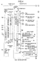
- FIG. 4 shows an electric circuit of the indoor unit 10.
- the electric circuit has a power supply board 70 and a control board 72.
- the power supply board 70 has a drive circuit 70A, a motor power supply circuit 70B, a control circuit power supply circuit 70C, and a serial circuit power supply circuit 70D.
- the drive circuit 70A is connected to the fan motor 70E that controls the amount of air supplied to the room.
- the motor power supply circuit 70B generates the power for driving various motors.
- the control circuit power supply circuit 70C generates power for the control circuit.
- the serial circuit power supply circuit 70D generates the power for the serial circuit.
- the control board 72 has a serial circuit 72A, a drive circuit 72B, and a microcomputer 72C.
- the serial circuit 72A is connected to the serial circuit power supply circuit 70D.
- the drive circuit 72B drives a motor.
- the microcomputer 72C functions as a control circuit.
- the drive circuit 72B is connected to an up/down flap motor 74A, left/right flap motors 74B and 74C, and a floor sensor motor 74D.
- the up/down flap motor 74A vertically moves a flap.
- the floor sensor motor 74D rotates a floor sensor that detects the temperature of the entire surface of the floor.
- the microcomputer 72C is connected to a display LED, an optical sensor 76B, and a receiving circuit 76A.
- the display LED is disposed on the display board 76 and displays an operation mode and so forth.
- the receiving circuit 76A receives an operation signal as infrared rays through the optical sensor 76B from the remote controller 14.
- the microcomputer 72C is connected to an area LED and a floor sensor.
- the area LED is disposed on a sensor board 78 and displays the temperature detecting area of the floor.
- the remote controller 14 causes the air conditioner to drive the flap motors 74A, 74B and 74C and exchange the flap angles and so forth, thereby selecting each mode of heating mode, cooling mode, dry mode, automatic operating mode, sleep mode, and so forth and changes the designated temperature, and amount of air supplied to the air conditioner.
- the microcomputer 72C is connected to a room temperature sensor 80A, a heat exchanger temperature sensor 80B, and a humidity sensor 80C.
- the room temperature sensor 80A detects the room temperature.
- the heat exchanger temperature sensor 80B detects the temperature of the refrigerant coil of the indoor heat exchanger 16.
- the humidity sensor 80C detects the humidity of the room.
- the microcomputer 72A is connected to self diagnosis switch that are disposed on the switch board 82. The operation selection switch selects one of the heating mode, the cooling mode, the dry mode, and the automatic operation mode.
- Display LEDs corresponding to the "heating mode”, “cooling mode”, “dry mode”, “automatic operation mode”, and “sleep mode” are disposed on the display board 76 and light corresponding to the operation modes.
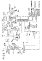
- FIG 5 shows an electric circuit of the outdoor unit 12.
- This electric circuit has a rectifier circuit 100 and a control board 102. Terminals (1) to (3) of the electric circuit of the outdoor unit 12 are connected to the electric circuit of the indoor unit 10 shown in Figure 4.
- the control board 102 has a serial circuit 102A, noise filters 102B, 102C, and 120D, a switching power supply circuit 102E, and microcomputer 102F.
- the serial circuit 102A is connected to the serial circuit power supply circuit 70D of the indoor unit 10.
- the noise filters 102B, 102C, and 120D remove noise.
- the switching power supply circuit 102E generates a power for switching the inverter 104.
- the microcomputer 102F functions as a control circuit.
- the switching power supply circuit 102E is connected to the inverter 104.
- the inverter 104 is connected to the compressor 26, which compresses the refrigerant.
- the microcomputer 102F is connected to an outer air temperature thermistor 110A, a coil temperature thermistor 110B, and a compressor temperature thermistor 110C.
- the outer air temperature thermistor 110A is an outer temperature sensor that detects the temperature of the outer air.
- the coil temperature thermistor 110B is a coil temperature sensor that detects the temperature of the refrigerant coil of the outdoor heat exchanger 28.
- the compressor temperature thermistor 110C is a temperature sensor that detects the temperature of the compressor 26.
- the noise filter 102B is connected to a fan motor 112A and a fan motor condenser 112B.
- the fan motor 112A supplies air to the outdoor heat exchanger 28.
- the four-way valve 27, which changes the flow direction of the refrigerant supplied from the compressor 26, is connected to the noise filter 102B.
- an operating signal is received by the receiving circuit 76A, and to determine whether or not the signal is a power on command or a timer designating command.
- a signal can be input so that the air conditioner will automatically operate at a predetermined time (for example, two hours later).
- the air conditioner When a power on command is detected, the air conditioner starts in the designated mode of the last operation.
- the received operation signal is analysed and it is determined whether or not the analysed result is a power off command, an air amount designating (changing) command, a temperature designating (changing) command, or a timer designating (changing) command.
- the determined result an item corresponding to the analysed result is selected.
- the operation of the air conditioner is stopped or the designated operation mode is executed.
- a desired temperature is designated with the temperature designating keys of the remote controller 14 and then the sleep mode switch button is pressed. With this key operation sequence, the remote controller 14 generates an operation signal.
- the operation signal is received by the receiving circuit 76A, the operation signal is analysed and it is determined that the operation signal represents the sleep mode and the designated temperature (desired temperature).
- the fan motor 70, the compressor 26, and so forth are controlled so that the air amount and the temperature are changed to provide a sleeping environment having an optimum temperature.
- a flag for causing a designated temperature (desired temperature) shift control to be executed once is initialised.
- "0" is stored in a flag register fr.
- the designated temperature t0 at present time is stored to the register.
- the room temperature t is detected by the room temperature sensor 80A.
- of the room temperature and the designated temperature t0 is obtained.
- is denoted by ⁇ t and stored in the register.
- the indoor unit 10 performs a fuzzy operation corresponding to ⁇ t and the variation of ⁇ t so as to calculate an increase/decrease amount ⁇ F of a frequency F for controlling the AC motor of the compressor 26.
- the frequency F for controlling the AC motor represents the operation power of the air conditioner.
- the operation power of the air conditioner in the case that the AC motor of the compressor is controlled corresponding to the frequency F is denoted by an operation power F.
- the increase/decrease amount ⁇ F of the operation power F calculated by the indoor unit 10 is sent to the outdoor unit 12 through a signal line.
- the outdoor unit 12 increases or decreases the operation power F at the time (namely, the frequency F of the AC motor) corresponding to the increase/decrease amount ⁇ F of the received operation power.
- the resultant operation power is denoted by F'.
- F' the operation power F is increased with a small amplitude.
- the room temperature is effectively approached to the designated temperature.
- the maximum power (maximum frequency) F is maintained.
- the real operation power F' is compensated by the microcomputer 102F of the outdoor unit 12 corresponding to various factors such as the current power consumption of the air conditioner at the present time, the temperature of the compressor 26, and the temperature of outside air.
- the real operation power F' is not always changed for ⁇ F, which is calculated by the indoor unit 10.
- the operation power F' tends to converge to an operation power that is balanced with the load of the air conditioner.
- step 314 it is determined whether or not the sleep mode has been selected.
- the flow advances to step 322.
- step 322 "0" is stored in the flag register fr. Thus, even if the sleep mode is selected after it is cleared, the temperature shift (compensation) control is performed. Thereafter, the flow returns to step 302. At step 302, the above-described process is repeated.
- the flow advances to the next step 316.
- the operation power F' obtained by the microcomputer 102F of the outdoor unit 12 is sent from the outdoor unit 12 to the indoor unit 10 through a signal line.
- the microcomputer 72C of the indoor unit 10 compares the received operation power F' with the operation power F stored before a predetermined time and calculates the increase/decrease amount ⁇ F' of the real operation power.
- ⁇ F' When ⁇ F' is a large positive value, the load of the air conditioner has been increased (namely, a window or a door has been opened or the room temperature exceeds the designated temperature). Thus, at this point, a large operation power is required. On the other hand, when ⁇ F' is a large negative value, the load of the air conditioner decreases (namely, the designated temperature has been changed). Thus, the required operation power becomes small.
- the absolute value of ⁇ F' is small, the magnitude of the load is balanced with the operation power F (namely, the designated temperature t0 almost accords with the room temperature t).
- step 320 it is determined whether or not the absolute value
- the constant T is designated in the range from 2 Hz to 5 Hz corresponding to the maximum operation power and so forth.
- the flow advances to step 322.
- step 322 "0" is stored in the flag resister fr. Thereafter, the flow returns to step 302.
- step 302 the above-described process is repeated. Thus, even, if the sleep mode is selected after it is cleared, the temperature shift control can be executed.
- the determined result is YES (namely,
- the flow advances to step 324.
- step 324 it is determined whether or not the content of the flag register fr is "1".
- the flow returns to step 302.
- the above-described process is repeated.
- the flow advances to the next step 326.
- "1" is stored in the flag register fr.
- step 328 it is determined whether the cooling mode or the heating mode has been selected.
- the flow advances to step 330.
- the flow advances to step 332.
- step 330 the value of the designated temperature t0 stored in the designated temperature register is read. The value of which 2 °C is added to t0 is stored in the designated temperature register. Thereafter, the flow returns to step 302. At step 302, the temperature control is performed corresponding to the designated temperature increased by 2°C. Of course, since the value of the flag register fr is "1", the designated temperature shift control is not performed. Unless the sleep mode is cleared, the changed designated temperature is maintained. Thus, the room temperature is not abnormally changed.
- an automatic temperature restoring function can be provided so that the initially designated temperature is restored when the sleep mode is cleared after the temperature shift control is performed.
- step 332 the value of the designated temperature t0 stored in the designated temperature resistor is read. The value of 2 °C is subtracted from t0 and the result is stored in the designated temperature register. Thereafter, the flow returns to step 302.
- step 302 the temperature control is performed for the designated temperature decreased by 2 °C. Likewise, while the designated temperature is maintained, the temperature control is performed.
- the temperature shift amount 2 °C was used.
- the temperature shift amount should be designated corresponding to the decrease in body temperature of a person who is asleep in the air conditioned environment.
- the temperature shift amount may be other than 2 °C.
- the temperature shift amount may be selected by the user.
- the temperature shift amount may be a function of the room temperature or a function of the designated temperature, instead of a constant.
- the temperature shift amount in the heating mode may be a function that is different from a function of the temperature shift amount in the cooling mode.
- the temperature shift amount can be selected corresponding to each application.
- Figures 7 and 8 are graphs showing time changes of the room temperature t in the case that the above-described operation power control is performed.
- Figure 7 is a graph showing a time change of the room temperature t in the case that the room temperature t is within the designated temperature t0 in the heating mode.
- a solid line 400 is a curve that represents a time change of the room temperature t in the case that temperature shift control according to the invention is performed.
- a dashed line 402 is a curve that represents a time change of the room temperature t in the case that the conventional temperature shift control is performed.
- the room temperature t increases from the initial room temperature ts and asymptotically approaches a straight line 404 that represents the designated temperature t0.
- the variation width ⁇ F' of the real operation power gradually decreases.
- ⁇ F' is T (for example, 3Hz) or less.
- the designated temperature t0 is shifted to t0 - 2 °C.
- the solid line 400 asymptotically approaches a straight line 406. Consequently, the room temperature t is maintained at the designated temperature t0 - 2 °C.
- the room temperature t increases from the initial room temperature ts as with the solid line 400. However, when the room temperature t almost accords with the designated temperature t0, the designated temperature is shifted to t0 - 2 °C. Thus, the dashed line 402 parts from the solid line 400. Thereafter, the dashed line 402 asymptotically approaches the straight line 406. Thus, the room temperature t is maintained at the designated temperature t0 - 2 °C.
- Figure 8 is a graph showing the temperature of a room against time in the case that the room temperature t is within the designated temperature t0 in the cooling mode.
- a solid line 420 is a curve that represents a time change of the room temperature t in the case that the temperature shift control according to the invention is performed.
- a dashed line 422 is a curve that represents a time change of the room temperature t in the case that the conventional temperature shift control is performed.
- the room temperature t decreases from the initial room temperature ts. Thereafter, the solid line asymptotically approaches a straight line 424 that represents the designated temperature t0.
- the variation width ⁇ F' of the real operation power gradually decreases.
- ⁇ F' is T (for example, 3 Hz) or less.
- the frequency for maintaining the designated temperature is designated.
- the designated temperature is maintained.
- the solid line 420 asymptotically approaches a straight line 426.
- the room temperature t is maintained at the designated temperature t0 + 2 °C.
- the room temperature t decreases from the initial room temperature ts as with the solid line 420. However, when the room temperature t almost accords with the designated temperature t0, the designated temperature is shifted to t0 + 2 °C. Thus, the dashed line 422 parts from the solid line 420 and asymptotically approaches a straight line 426 that represents the designated temperature t0 + 2 °C. Thus, the room temperature t is maintained at the designated temperature t0 + 2 °C.
- the air conditioner when the variation width ⁇ F' of the frequency for controlling the AC motor converges to a predetermined range, it is determined that the power of the air conditioner that is operating approaches the predetermined range of the power for maintaining the designated temperature. Thereafter, the temperature shift control is performed.
- the air conditioner can provide the user for a comfortable sleeping environment.
- the power of the air conditioner converges to an operation power of which the load of the air conditioner is balanced with the operation power at a temperature that is different from the designated temperature (desired temperature) and thereby the operation of the air conditioner becomes stable.
- the conventional air conditioner performs the temperature shift control corresponding to the difference between the designated temperature and the room temperature, it cannot detect a match of the room temperature and the designated temperature. Thus, the air conditioner may not occasionally change the designated temperature.
- the air conditioner even if the operation of the air conditioner becomes stable, since the air conditioner can detect a decrease of the variation width of the operation power, it can determine an occurrence of the stable state of the operation and thereby properly perform the designated temperature shift control.
- the present invention is not limited to the above-described embodiment.
- the frequency for controlling the AC motor was used as a means for representing the power of the air conditioning.
- another means can be used as long as it accurately represents the power of the air conditioner. For example, by controlling the voltage applied to a DC motor, the power of the air conditioner (the number of rotations of the DC motor) can be controlled.
- a means for determining whether or not the power of the air conditioner that is operating approaches a predetermined range necessary for maintaining a designed temperature another method using other than AF' can be used.
- a method for estimating a power K0 for maintaining the predetermined temperature and for comparing K0 with a present power K of the air conditioner can be used.
- any method can be used as long as it is determined whether or not the power of the air conditioner becomes stable at a temperature near the predetermined temperature and whether or not the power of the air conditioner approaches the predetermined range.
- the temperature shift control was performed in the sleep mode.
- the temperature shift control can be performed in another mode as long as it prevents the designated temperature from becoming improper due to for example a change of the body temperature of the user.
- the number of times of the temperature shift control can be three or more, not limited to one and two.
- the air conditioner of the present invention when the sleep mode or the like is selected, the variation of the rotations for controlling the motor of the compressor is detected. When the variation converges to the predetermined range, the designated (desired temperature) is shifted (compensated) to the predetermined temperature.
- the air conditioner of the present invention can provide a user for a comfortable sleeping temperature environment although the body temperature of the user decreases.
- the load of the air conditioner is balanced with the operation power at a temperature that is different from the designated temperature and thereby the operation becomes stable, since the stable can be determined, the same effect can be accomplished.
- the present invention since the temperature shift control is occasionally performed before the room reaches the designated temperature, the present invention contributes to energy saving.
Landscapes
- Engineering & Computer Science (AREA)
- Chemical & Material Sciences (AREA)
- Combustion & Propulsion (AREA)
- Mechanical Engineering (AREA)
- General Engineering & Computer Science (AREA)
- Physics & Mathematics (AREA)
- Human Computer Interaction (AREA)
- Signal Processing (AREA)
- General Physics & Mathematics (AREA)
- Automation & Control Theory (AREA)
- Fuzzy Systems (AREA)
- Mathematical Physics (AREA)
- Fluid Mechanics (AREA)
- Thermal Sciences (AREA)
- Air Conditioning Control Device (AREA)
Claims (6)
- Klimagerät, das betätigbar ist, um zu bewirken, daß sich eine Temperatur eines Raumes einer bestimmten Temperatur nähert, gekennzeichnet durch Mittel (72C, 102F) zum Erfassen, ob der von dem Klimagerät verbrauchte Strom innerhalb eines vorbestimmten Bereichs liegt, und Mittel (72C 102F) zum Ausgleichen der bestimmten Temperatur, wenn der vorbestimmte Bereich erreicht ist.
- Klimagerät nach Anspruch 1, wobei das Mittel (72C, 102F) zum Ausgleichen der bestimmten Temperatur einen Schalter enthält, wobei das Mittel betätigbar ist, um die bestimmte Temperatur in Abhängigkeit von der Stellung des Schalters auszugleichen.
- Klimagerät nach Anspruch 1 oder 2, wobei das Mittel (72C, 102F) zum Ausgleichen die bestimmte Temperatur senkt, wenn ein Heizmodus gewählt ist.
- Klimagerät nach einem der vorangehenden Ansprüche, wobei das Mittel (72C, 102F) zum Ausgleichen die bestimmte Temperatur erhöht, wenn ein Kühlmodus gewählt ist.
- Klimagerät nach einem der vorangehenden Ansprüche, wobei das Mittel (72C, 102F) zum Ausgleichen der Temperatur zum mehrmaligen Ausgleichen der Temperatur in einer bestimmten Periode betätigbar ist.
- Klimagerät nach einem der vorangehenden Ansprüche, umfassend einen Kompressor (26), einen Kondensator, eine Entspannungsvorrichtung und einen Verdampfer.
Applications Claiming Priority (3)
| Application Number | Priority Date | Filing Date | Title |
|---|---|---|---|
| JP6241386A JPH08105644A (ja) | 1994-10-05 | 1994-10-05 | 空気調和機 |
| JP241386/94 | 1994-10-05 | ||
| JP24138694 | 1994-10-05 |
Publications (3)
| Publication Number | Publication Date |
|---|---|
| EP0706106A2 EP0706106A2 (de) | 1996-04-10 |
| EP0706106A3 EP0706106A3 (de) | 1996-09-11 |
| EP0706106B1 true EP0706106B1 (de) | 2000-03-01 |
Family
ID=17073519
Family Applications (1)
| Application Number | Title | Priority Date | Filing Date |
|---|---|---|---|
| EP95306421A Expired - Lifetime EP0706106B1 (de) | 1994-10-05 | 1995-09-13 | Klimaanlage |
Country Status (8)
| Country | Link |
|---|---|
| US (1) | US5568733A (de) |
| EP (1) | EP0706106B1 (de) |
| JP (1) | JPH08105644A (de) |
| KR (1) | KR100327069B1 (de) |
| CN (1) | CN1092782C (de) |
| BR (1) | BR9504308A (de) |
| CA (1) | CA2158489C (de) |
| DE (1) | DE69515243T2 (de) |
Cited By (1)
| Publication number | Priority date | Publication date | Assignee | Title |
|---|---|---|---|---|
| US6881205B2 (en) | 2000-10-27 | 2005-04-19 | Kimberly-Clark Worldwide, Inc. | Independence of components in absorbent articles |
Families Citing this family (15)
| Publication number | Priority date | Publication date | Assignee | Title |
|---|---|---|---|---|
| JPH09113003A (ja) * | 1995-10-23 | 1997-05-02 | Sanyo Electric Co Ltd | 空気調和機 |
| FR2755215B1 (fr) * | 1996-10-28 | 1999-01-08 | Valeo Climatisation | Installation de chauffage, ventilation et/ou climatisation a regulation par logique floue, notamment pour vehicule automobile |
| DE10312694B4 (de) * | 2003-03-21 | 2007-06-21 | Stiebel Eltron Gmbh & Co. Kg | Gerätesteuerung |
| US7775454B2 (en) * | 2007-05-11 | 2010-08-17 | Emerson Electric Co. | Load management thermostat |
| WO2007090400A1 (en) * | 2006-02-10 | 2007-08-16 | Danfoss A/S | Method and system for controlling the climate in a house |
| US7531977B2 (en) * | 2006-09-19 | 2009-05-12 | Ise Corporation | HVAC system and method for over the road motor coaches |
| CN101886840B (zh) * | 2010-02-25 | 2012-09-26 | 海尔集团公司 | 一种空调压缩机频率控制方法及空调器 |
| JP2013092270A (ja) * | 2011-10-24 | 2013-05-16 | Panasonic Corp | 省エネルギー装置、省エネルギーシステムおよびプログラム |
| CN103486820B (zh) * | 2013-09-12 | 2015-12-09 | 泰州乐金电子冷机有限公司 | 温度调节装置、冰箱及温度调节方法 |
| CN104949265B (zh) * | 2015-06-03 | 2018-09-07 | 广东美的暖通设备有限公司 | 空调系统及空调系统的能源管理方法 |
| CN105352126A (zh) * | 2015-11-23 | 2016-02-24 | 珠海格力电器股份有限公司 | 空调器控制方法和系统 |
| CN105546750A (zh) * | 2016-01-05 | 2016-05-04 | 青岛海尔空调器有限总公司 | 床式与壁挂式或柜式一拖二空调器及其控制方法 |
| JPWO2018029783A1 (ja) * | 2016-08-09 | 2019-03-28 | 三菱電機株式会社 | 空気調和装置 |
| CN108518827B (zh) * | 2018-02-28 | 2019-09-20 | 珠海格力电器股份有限公司 | 空调系统的控制方法及空调系统 |
| CN116772301B (zh) * | 2023-06-21 | 2025-10-28 | 珠海格力电器股份有限公司 | 一种便携式空调 |
Family Cites Families (8)
| Publication number | Priority date | Publication date | Assignee | Title |
|---|---|---|---|---|
| US4335847A (en) * | 1980-05-27 | 1982-06-22 | Levine Michael R | Electronic thermostat with repetitive operation cycle |
| FR2536837B1 (fr) * | 1982-11-30 | 1988-03-04 | Electricite De France | Procede et dispositif de regulation du chauffage de locaux |
| JPS60142140A (ja) * | 1983-12-28 | 1985-07-27 | Matsushita Electric Ind Co Ltd | 空気調和機 |
| US4702305A (en) * | 1987-03-30 | 1987-10-27 | Honeywell Inc. | Temperature control system for control of a multiplant environmental unit |
| US5372015A (en) * | 1991-07-05 | 1994-12-13 | Kabushiki Kaisha Toshiba | Air conditioner controller |
| JPH0599484A (ja) * | 1991-07-12 | 1993-04-20 | Mitsubishi Electric Corp | 空気調和機の運転制御装置 |
| JPH0683113A (ja) * | 1992-09-01 | 1994-03-25 | Sanyo Chem Ind Ltd | 荷電制御剤 |
| US5410890A (en) * | 1994-01-27 | 1995-05-02 | Fujitsu General Limited | Control apparatus of air-conditioner |
-
1994
- 1994-10-05 JP JP6241386A patent/JPH08105644A/ja active Pending
-
1995
- 1995-03-16 KR KR1019950005440A patent/KR100327069B1/ko not_active Expired - Fee Related
- 1995-09-13 EP EP95306421A patent/EP0706106B1/de not_active Expired - Lifetime
- 1995-09-13 DE DE69515243T patent/DE69515243T2/de not_active Expired - Lifetime
- 1995-09-14 CA CA002158489A patent/CA2158489C/en not_active Expired - Fee Related
- 1995-09-29 US US08/536,440 patent/US5568733A/en not_active Expired - Lifetime
- 1995-10-04 CN CN95117231A patent/CN1092782C/zh not_active Expired - Fee Related
- 1995-10-05 BR BR9504308A patent/BR9504308A/pt not_active IP Right Cessation
Cited By (1)
| Publication number | Priority date | Publication date | Assignee | Title |
|---|---|---|---|---|
| US6881205B2 (en) | 2000-10-27 | 2005-04-19 | Kimberly-Clark Worldwide, Inc. | Independence of components in absorbent articles |
Also Published As
| Publication number | Publication date |
|---|---|
| CA2158489C (en) | 1999-03-30 |
| DE69515243D1 (de) | 2000-04-06 |
| US5568733A (en) | 1996-10-29 |
| EP0706106A3 (de) | 1996-09-11 |
| CN1092782C (zh) | 2002-10-16 |
| KR100327069B1 (ko) | 2002-08-21 |
| CA2158489A1 (en) | 1996-04-06 |
| EP0706106A2 (de) | 1996-04-10 |
| BR9504308A (pt) | 1996-10-08 |
| JPH08105644A (ja) | 1996-04-23 |
| DE69515243T2 (de) | 2000-09-07 |
| CN1132338A (zh) | 1996-10-02 |
| KR960014815A (ko) | 1996-05-22 |
Similar Documents
| Publication | Publication Date | Title |
|---|---|---|
| US5568733A (en) | Air conditioner | |
| US5588589A (en) | Air conditioner | |
| US5568732A (en) | Air conditioning apparatus and method of controlling same | |
| JPH05229334A (ja) | 空気調和装置 | |
| KR900005721B1 (ko) | 공기조화기의 운전제어장치 | |
| KR100315155B1 (ko) | 공기조화기의제어장치 | |
| JPH0989347A (ja) | 空気調和機 | |
| US4840220A (en) | Heat pump with electrically heated heat accumulator | |
| KR100359179B1 (ko) | 공기조화기 | |
| JP2006118732A (ja) | 空気調和機 | |
| JPH11132528A (ja) | 空気調和機 | |
| JPH08193742A (ja) | 空気調和機 | |
| JP3306126B2 (ja) | 空気調和機 | |
| JPH1096548A (ja) | 空気調和機 | |
| JPH0633896B2 (ja) | 空気調和機の除霜制御方法 | |
| JPH09152180A (ja) | 空気調和機の空気調和方法 | |
| JPH04288438A (ja) | 空気調和装置 | |
| JPH09152173A (ja) | 空気調和機 | |
| JP3865004B2 (ja) | 空気調和機の制御方法 | |
| KR0140567B1 (ko) | 냉/난방 겸용 에어컨의 실내/외 팬 제어방법 | |
| JPS6134054B2 (de) | ||
| JPS6131860A (ja) | 冷凍サイクル | |
| JPS61159042A (ja) | 空気調和機 | |
| KR100248776B1 (ko) | 공기조화기의운전제어방법 | |
| JPH03233242A (ja) | 空気調和機 |
Legal Events
| Date | Code | Title | Description |
|---|---|---|---|
| PUAI | Public reference made under article 153(3) epc to a published international application that has entered the european phase |
Free format text: ORIGINAL CODE: 0009012 |
|
| AK | Designated contracting states |
Kind code of ref document: A2 Designated state(s): DE FR GB IT |
|
| PUAL | Search report despatched |
Free format text: ORIGINAL CODE: 0009013 |
|
| AK | Designated contracting states |
Kind code of ref document: A3 Designated state(s): DE FR GB IT |
|
| 17P | Request for examination filed |
Effective date: 19961024 |
|
| 17Q | First examination report despatched |
Effective date: 19981208 |
|
| GRAG | Despatch of communication of intention to grant |
Free format text: ORIGINAL CODE: EPIDOS AGRA |
|
| GRAG | Despatch of communication of intention to grant |
Free format text: ORIGINAL CODE: EPIDOS AGRA |
|
| GRAH | Despatch of communication of intention to grant a patent |
Free format text: ORIGINAL CODE: EPIDOS IGRA |
|
| GRAH | Despatch of communication of intention to grant a patent |
Free format text: ORIGINAL CODE: EPIDOS IGRA |
|
| GRAA | (expected) grant |
Free format text: ORIGINAL CODE: 0009210 |
|
| AK | Designated contracting states |
Kind code of ref document: B1 Designated state(s): DE FR GB IT |
|
| REF | Corresponds to: |
Ref document number: 69515243 Country of ref document: DE Date of ref document: 20000406 |
|
| ET | Fr: translation filed | ||
| ITF | It: translation for a ep patent filed | ||
| PLBE | No opposition filed within time limit |
Free format text: ORIGINAL CODE: 0009261 |
|
| STAA | Information on the status of an ep patent application or granted ep patent |
Free format text: STATUS: NO OPPOSITION FILED WITHIN TIME LIMIT |
|
| 26N | No opposition filed | ||
| REG | Reference to a national code |
Ref country code: GB Ref legal event code: IF02 |
|
| PGFP | Annual fee paid to national office [announced via postgrant information from national office to epo] |
Ref country code: IT Payment date: 20080926 Year of fee payment: 14 |
|
| PGFP | Annual fee paid to national office [announced via postgrant information from national office to epo] |
Ref country code: GB Payment date: 20080917 Year of fee payment: 14 |
|
| PGFP | Annual fee paid to national office [announced via postgrant information from national office to epo] |
Ref country code: DE Payment date: 20090910 Year of fee payment: 15 |
|
| PGFP | Annual fee paid to national office [announced via postgrant information from national office to epo] |
Ref country code: FR Payment date: 20091012 Year of fee payment: 15 |
|
| GBPC | Gb: european patent ceased through non-payment of renewal fee |
Effective date: 20090913 |
|
| PG25 | Lapsed in a contracting state [announced via postgrant information from national office to epo] |
Ref country code: GB Free format text: LAPSE BECAUSE OF NON-PAYMENT OF DUE FEES Effective date: 20090913 |
|
| PG25 | Lapsed in a contracting state [announced via postgrant information from national office to epo] |
Ref country code: IT Free format text: LAPSE BECAUSE OF NON-PAYMENT OF DUE FEES Effective date: 20090913 |
|
| REG | Reference to a national code |
Ref country code: FR Ref legal event code: ST Effective date: 20110531 |
|
| REG | Reference to a national code |
Ref country code: DE Ref legal event code: R119 Ref document number: 69515243 Country of ref document: DE Effective date: 20110401 |
|
| PG25 | Lapsed in a contracting state [announced via postgrant information from national office to epo] |
Ref country code: DE Free format text: LAPSE BECAUSE OF NON-PAYMENT OF DUE FEES Effective date: 20110401 Ref country code: FR Free format text: LAPSE BECAUSE OF NON-PAYMENT OF DUE FEES Effective date: 20100930 |