EP0707080B1 - Procede de production d'acier fondu a faible teneur en carbone par degazage et decarburation sous vide - Google Patents
Procede de production d'acier fondu a faible teneur en carbone par degazage et decarburation sous vide Download PDFInfo
- Publication number
- EP0707080B1 EP0707080B1 EP94917160A EP94917160A EP0707080B1 EP 0707080 B1 EP0707080 B1 EP 0707080B1 EP 94917160 A EP94917160 A EP 94917160A EP 94917160 A EP94917160 A EP 94917160A EP 0707080 B1 EP0707080 B1 EP 0707080B1
- Authority
- EP
- European Patent Office
- Prior art keywords
- gas
- molten steel
- decarburization
- blowing
- vacuum
- Prior art date
- Legal status (The legal status is an assumption and is not a legal conclusion. Google has not performed a legal analysis and makes no representation as to the accuracy of the status listed.)
- Expired - Lifetime
Links
Images


Classifications
-
- C—CHEMISTRY; METALLURGY
- C21—METALLURGY OF IRON
- C21C—PROCESSING OF PIG-IRON, e.g. REFINING, MANUFACTURE OF WROUGHT-IRON OR STEEL; TREATMENT IN MOLTEN STATE OF FERROUS ALLOYS
- C21C7/00—Treating molten ferrous alloys, e.g. steel, not covered by groups C21C1/00 - C21C5/00
- C21C7/10—Handling in a vacuum
-
- C—CHEMISTRY; METALLURGY
- C21—METALLURGY OF IRON
- C21C—PROCESSING OF PIG-IRON, e.g. REFINING, MANUFACTURE OF WROUGHT-IRON OR STEEL; TREATMENT IN MOLTEN STATE OF FERROUS ALLOYS
- C21C7/00—Treating molten ferrous alloys, e.g. steel, not covered by groups C21C1/00 - C21C5/00
- C21C7/04—Removing impurities by adding a treating agent
- C21C7/068—Decarburising
-
- F—MECHANICAL ENGINEERING; LIGHTING; HEATING; WEAPONS; BLASTING
- F27—FURNACES; KILNS; OVENS; RETORTS
- F27D—DETAILS OR ACCESSORIES OF FURNACES, KILNS, OVENS OR RETORTS, IN SO FAR AS THEY ARE OF KINDS OCCURRING IN MORE THAN ONE KIND OF FURNACE
- F27D27/00—Stirring devices for molten material
- F27D2027/002—Gas stirring
Definitions
- This invention relates to a vacuum degassing and decarburization treatment for a molten steel using a vacuum degassing equipment, and more particularly to a production method, for a low carbon molten steel, which is advantageous from the aspects of cost of production and high efficiency, using a vacuum degassing and decarburization treatment which improves the recirculating or stirring gas for a molten steel.
- a method which exposes a molten steel to a reduced pressure by using vacuum treatment equipment is known as a method of degassing and decarburizing a molten steel according to the prior art.
- This method is a decarburization treatment method which promotes the reaction C + 1/2 O 2 ⁇ CO by reducing the pressure.
- the vacuum treatment equipment includes a lance and/or a tuyere for blowing an Ar gas into the molten steel so as to recirculate or stir the molten steel and to promote the treatment, a double tuyere for simultaneously blowing oxygen necessary for deoxidization and Ar for cooling it, and a lance and/or a tuyere for blowing Ar into the molten steel so as to stir the molten steel by the resulting fine bubbles, and to promote the treatment by increasing the area of the reaction interface.
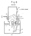
- Fig. 8 shows these members of an RH vacuum treatment equipment, by way of example.
- reference numeral 27 denotes an Ar gas blast tuyere for recirculating the molten steel between a molten steel ladle 21 and a vacuum degassing vessel
- reference numeral 28 denotes an Ar gas blast tuyere for stirring the molten steel
- reference numeral 24 denotes an Ar gas blast tuyere for recirculating the molten steel between the molten steel ladle 21 and the vacuum degassing vessel
- reference numeral 30 denotes a double tuyere for simultaneously blowing oxygen necessary for decarburization from an inner pipe and an Ar gas for cooling the inner pipe and a refractory around the inner pipe from an outer pipe. Because the Ar gas is blown from these lances and/or tuyeres, vacuum degassing and decarburization treatment can be promoted.
- JP-A-56-44711 discloses a method which blows a CO 2 gas during treatment by using a single pipe in place of the double pipe. This is the method which vacuum decarburizes the molten steel by the endothermic reaction C + CO 2 ⁇ 2CO.
- the decarburization reaction does not proceed below a certain carbon concentration of the molten steel even when the CO 2 gas is blown into the molten steel, and a low carbon steel having a carbon concentration of below 50 (ppm) cannot be produced.
- a deoxidizing alloy such as Al or Si
- the oxygen concentration increases, on the contrary, when CO 2 is continuously blown into the molten steel even after the addition of this alloy, so that an excessive amount of the alloy must be added to remove this oxygen, and the resulting fine oxides deteriorate the cleanness of the molten steel.
- JP-A-56 044 711 discloses inblow of CO 2 through a tuyere below the steel bath surface in a RH vacuum vessel in order to decarburize the steel without generating heat while Ar is blown in through a lower tuyere to assist recirculation.
- JP-A-2 267 213 discloses inblow of Ar through side blow tuyeres below the steel bath surface in a RH vacuum vessel in order to accelerate decarburization in producing extremely low C steel.
- the present invention relates to a method of economically, and moreover, without any troubles, producing a molten steel by partly replacing the expensive Ar gas by an economical gas.
- the inventors of the present invention have examined the relationship between a CO 2 gas and a decarburization speed of a molten steel by conducting various experiments when the CO 2 gas is used as a gas for recirculating or stirring the molten steel inside an RH vacuum degassing vessel using vacuum degassing equipment.
- an immersion pipe 3 of an RH vacuum degassing vessel 9 is immersed into a molten steel 2 inside a molten steel ladle 1, and a CO 2 gas and an Ar gas are blown as gasses for recirculating the molten steel from an injection nozzle 4 of an injection lance 5 disposed at a lower part of this immersion pipe 3.
- the Ar gas as a stirring gas is blown into the molten steel 2 from a stirring gas pipe 8 so as to recirculate the molten steel 2 inside the molten steel ladle 1, to stir the molten steel 2 and to decarburize it.
- Fig. 2 shows the time shift of a carbon concentration (thick line) of the molten steel 2 in this instance.
- the blown CO 2 gas decomposes into C and O, and the resulting carbon (C) dissolves into the molten steel 2.
- the carbon concentration of the molten steel 2 is relatively high from 150 to 300 (ppm)
- the quantity of C dissolved into the molten steel is relatively small, so that its influences hardly exists, and decarburization is quickly promoted in the same way as in the case of the Ar gas.
- the carbon concentration reaches the ranges of 50 to 150 (ppm)
- the decarburization rate drops.
- the carbon concentration of the molten steel 2 becomes about 50 (ppm)
- the dissolving quantity of C, resulting from the CO 2 gas, into the molten steel 2 balances the decarburization quantity, so that decarburization stops.
- decarburization can be economically carried out to a desired carbon concentration without inviting the stop of decarburization.
- decarburization can be carried out more economically to a desired carbon concentration without inviting the stop of decarburization by blowing the CO 2 gas into the molten steel from the start of the degassing treatment so as to subject the molten steel to the vacuum degassing decarburization treatment and switching the gas from the CO 2 gas to the Ar gas before the carbon concentration of the molten steel 2 reaches 50 (ppm).
- the gas cost becomes lower when switching of the gas is made at a lower carbon concentration between 50 and 150 (ppm), but the treatment time becomes longer as much as the lower concentration. Accordingly, when a long treatment time can be secured inside this RH vacuum degassing vessel 9, the CO 2 gas is preferably switched to the Ar gas before the carbon concentration reaches 50 (ppm) as stipulated by the third technical feature of the present invention, and when a long treatment time cannot be secured, the CO 2 gas is preferably switched to the Ar gas between the carbon concentration of 150 and 50 (ppm) as stipulated by the fourth technical feature of the present invention.
- a gas for protecting the lance or tuyere, which is not immersed in the molten steel, before and after the vacuum treatment may be CO 2 gas because it does not at all render any problem. Therefore, it is preferred to reduce the cost by using the CO 2 gas in place of the expensive Ar gas.
- the molten steel may be arbitrarily heated by adding the deoxidizing agent using Al or Si.
- the Ar gas is exclusively used, and the CO 2 gas is blown preferably from the start of the decarburization treatment of the molten steel till the carbon concentration of the molten steel is from 150 to 50 (ppm).
- the CO 2 gas is switched to the Ar gas. In this way, it has been found that decarburization can be conducted economically to a desired carbon concentration.
- Fig. 1 shows the lance and the tuyere when the Ar and CO 2 gasses are blown in the RH vacuum treatment equipment.
- reference numeral 7 denotes a gas blast tuyere for recirculating the molten steel between the molten steel ladle 1 and the vacuum degassing vessel 9
- reference numeral 8 denotes a gas blast tuyere for stirring the molten steel
- reference numeral 4 denotes a gas blast tuyere for recirculating the molten steel between the molten steel ladle 1 and the vacuum degassing vessel 9
- reference numeral 10 denotes a double tuyere for blowing oxygen necessary for decarburization from an inner pipe and for simultaneously blowing a gas for cooling the inner pipe and the refractory around the inner pipe from an outer pipe.
- the application of the finding of the present invention is not particularly limited to the RH vacuum treatment equipment having two immersion pipes but can be similarly applied to a DH vacuum treatment equipment having one immersion pipe, and to the case where a ladle is disposed inside a vacuum pit and the molten steel inside the ladle is vacuum treated.
- a to-be-treated molten steel 2 inside a molten steel ladle 1 having a molten steel quantity of 340 (t) and a carbon concentration of 310 (ppm) was controlled and treated inside the RH vacuum degassing vessel 9 so that a final target vacuum inside the RH degassing vessel was not higher than 2 (Torr).
- treatment was started by using 2.5 (N m 3 /min) of the CO 2 gas as the recirculating gas to be blown from the injection nozzle 4 and 4.5 (N m 3 /min) of the CO 2 gas as the stirring gas to be blown from the stirring gas pipe 8 as shown in Fig. 3. Both of these CO 2 gases were switched to the Ar gas (in the same quantity as each of the CO 2 gas) at the time at which the carbon concentration of the treated molten steel 2 was estimated as 150 (ppm) (six minutes from the start of the treatment). As a Comparative Example, the operation was similarly carried out by blowing the same quantity of the Ar gas alone.
- a to-be-treated molten steel 2 inside a molten steel ladle 1 having a molten steel quantity of 342 (t) and a carbon concentration of 320 (ppm) was controlled and treated inside the RH vacuum degassing vessel 9 shown in Fig. 1 so that a final target value of vacuum was not higher than 2 (Torr).
- treatment was started by using 2.5 (N m 3 /min) of the CO 2 gas as the recirculating gas to be blown from the injection nozzle 4 and 4.5 (N m 3 /min) of the CO 2 gas as the stirring gas to be blown from the stirring gas pipe 8 as shown in Fig. 4. Both of these CO 2 gases were switched to the Ar gas (in the same quantity as each of the CO 2 gases) at the time at which the carbon concentration of the treated molten steel 2 was estimated as 100 (ppm). As a Comparative Example, the operation was similarly carried out by blowing the same quantity of the Ar gas alone.
- a to-be-treated molten steel 2 inside a molten steel ladle 1 having a molten steel quantity of 345 (t) and a carbon concentration of 303 (ppm) was controlled and treated inside the RH vacuum degassing vessel 9 shown in Fig. 1 so that a final target value of vacuum was not higher than 2 (Torr).
- a to-be-treated molten steel 2 inside a molten steel ladle 1 having a molten steel quantity of 353 (t) and a carbon concentration of 313 (ppm) was controlled and treated inside the RH vacuum degassing vessel 9 shown in Fig. 1 so that a final target value of vacuum was not higher than 2 (Torr).
- a to-be-treated molten steel 2 inside a molten steel ladle 1 having a molten steel quantity of 353 (t) and a carbon concentration of 560 (ppm) was controlled and treated inside the RH vacuum degassing vessel 9 shown in Fig. 1 so that a final target value of vacuum was not higher than 2 (Torr).
- the molten steel could be completely deoxidized by the same alloy feed quantity as when only the Ar gas was used, and about 42 (N m 3 /min) of the Ar gas could be replaced by the CO 2 gas without extending the RH degassing treatment time.
- the present invention uses the CO 2 gas as the recirculating gas and as the stirring gas from the start of the treatment, or for a predetermined period of time, and switches it to the Ar gas during the process in accordance with the carbon concentration of the molten steel or with the addition of the deoxidizing alloy.
- the present invention can execute the degassing treatment of the molten steel by using the more economical CO 2 gas and moreover, without inviting a stoppage of decarburization and an increase of the amount of addition of the deoxidizing alloy, and can reduce the gas cost of the vacuum treatment.
Landscapes
- Chemical & Material Sciences (AREA)
- Engineering & Computer Science (AREA)
- Materials Engineering (AREA)
- Metallurgy (AREA)
- Organic Chemistry (AREA)
- Treatment Of Steel In Its Molten State (AREA)
- Waste-Gas Treatment And Other Accessory Devices For Furnaces (AREA)
Claims (6)
- Procédé de décarburation et de dégazage sous vide d'un acier fondu pour la production d'un acier fondu à faible teneur en carbone, le procédé comprenant :la disposition d'un appareillage de traitement sous vide possédant une lance et/ou une tuyère de soufflage d'un gaz dans l'acier fondu,le soufflage de CO2 gazeux dans l'acier fondu par la lance et/ou la tuyère depuis le début de la décarburation du dégazage sous vide pour l'exécution d'un traitement de décarburation de dégazage sous vide de l'acier fondu par recirculation ou agitation de l'acier fondu par CO gazeux créé par décomposition de CO2 gazeux, etla commutation du soufflage de CO2 gazeux au soufflage d'argon gazeux uniquement dans l'acier fondu par la lance et/ou la tuyère dès que la concentration du carbone dans l'acier fondu atteint une valeur prédéterminée à laquelle la vitesse de décarburation de l'acier fondu diminue.
- Procédé de décarburation et de dégazage sous vide d'acier fondu selon la revendication 1, dans lequel le soufflage de CO2 gazeux est effectué lorsque la concentration de carbone de l'acier fondu est supérieure à 50 ppm, et le soufflage de l'argon gazeux est réalisé lorsque la concentration du carbone dans l'acier fondu ne dépasse pas 50 ppm.
- Procédé de décarburation et de dégazage sous vide d'acier fondu selon la revendication 1 ou 2, dans lequel le soufflage de CO2 gazeux est remplacé par le soufflage d'argon gazeux lorsque la concentration du carbone dans l'acier fondu atteint 50 ppm.
- Procédé de décarburation et de dégazage sous vide d'acier fondu selon la revendication 1, dans lequel le soufflage de CO2 gazeux est remplacé par le soufflage de l'argon gazeux lorsque la concentration du carbone dans l'acier fondu est comprise entre 150 et 50 ppm.
- Procédé de décarburation et de dégazage sous vide d'acier fondu destiné à la production d'un acier fondu à faible teneur en carbone, le procédé comprenant :la disposition d'un appareillage de traitement sous vide ayant une lance et/ou une tuyère de soufflage d'un gaz dans l'acier fondu,l'exécution d'un traitement de décarburation et de dégazage sous vide de l'acier fondu par soufflage de CO2 gazeux dans l'acier fondu à l'aide de la lance et/ou d'une tuyère dès le début du traitement de décarburation et de dégazage sous vide, etl'addition d'un agent de désoxydation à l'acier fondu pendant le traitement de décarburation et de dégazage sous vide,puis l'addition de l'agent de désoxydation, et le remplacement du soufflage de CO2 gazeux par un soufflage uniquement d'argon gazeux dans l'acier fondu par la lance et/ou la tuyère.
- Procédé de décarburation et de dégazage sous vide d'un acier fondu selon l'une quelconque des revendications 1 à 5, comprenant en outre une étape de soufflage d'argon gazeux dans l'acier fondu par la lance et/ou la tuyère pendant le soufflage de CO2 gazeux.
Applications Claiming Priority (4)
| Application Number | Priority Date | Filing Date | Title |
|---|---|---|---|
| JP134333/93 | 1993-06-04 | ||
| JP13433393 | 1993-06-04 | ||
| JP13433393 | 1993-06-04 | ||
| PCT/JP1994/000911 WO1994029488A1 (fr) | 1993-06-04 | 1994-06-06 | Procede de production d'acier fondu a faible teneur en carbone par degazage et decarburation sous vide |
Publications (3)
| Publication Number | Publication Date |
|---|---|
| EP0707080A1 EP0707080A1 (fr) | 1996-04-17 |
| EP0707080A4 EP0707080A4 (fr) | 1996-07-03 |
| EP0707080B1 true EP0707080B1 (fr) | 2001-04-04 |
Family
ID=15125893
Family Applications (1)
| Application Number | Title | Priority Date | Filing Date |
|---|---|---|---|
| EP94917160A Expired - Lifetime EP0707080B1 (fr) | 1993-06-04 | 1994-06-06 | Procede de production d'acier fondu a faible teneur en carbone par degazage et decarburation sous vide |
Country Status (9)
| Country | Link |
|---|---|
| US (1) | US5693120A (fr) |
| EP (1) | EP0707080B1 (fr) |
| JP (1) | JP3176374B2 (fr) |
| KR (1) | KR0159182B1 (fr) |
| CN (1) | CN1037783C (fr) |
| BR (1) | BR9406712A (fr) |
| CA (1) | CA2163893C (fr) |
| ES (1) | ES2155853T3 (fr) |
| WO (1) | WO1994029488A1 (fr) |
Cited By (1)
| Publication number | Priority date | Publication date | Assignee | Title |
|---|---|---|---|---|
| RU2215047C2 (ru) * | 2001-12-25 | 2003-10-27 | Открытое акционерное общество "Новолипецкий металлургический комбинат" | Устройство для циркуляционного вакуумирования стали |
Families Citing this family (19)
| Publication number | Priority date | Publication date | Assignee | Title |
|---|---|---|---|---|
| DE4328045C2 (de) * | 1993-08-20 | 2001-02-08 | Ald Vacuum Techn Ag | Verfahren zum Entkohlen von kohlenstoffhaltigen Metallschmelzen |
| US5603749A (en) * | 1995-03-07 | 1997-02-18 | Bethlehem Steel Corporation | Apparatus and method for vacuum treating molten steel |
| KR100270113B1 (ko) * | 1996-10-08 | 2000-10-16 | 이구택 | 극저탄소강의 용강 제조장치 |
| KR100627468B1 (ko) * | 2000-05-18 | 2006-09-22 | 주식회사 포스코 | 용강의 저취 교반방법 |
| WO2002048409A1 (fr) * | 2000-12-13 | 2002-06-20 | Kawasaki Steel Corporation | Procede servant a fabriquer un acier possedant une teneur elevee en azote et extremement basse en carbone |
| EP1568790A1 (fr) * | 2004-02-24 | 2005-08-31 | Paul Wurth S.A. | Dispositif pour le traitement de métal liquide en poche |
| CN102146498A (zh) * | 2010-02-05 | 2011-08-10 | 鞍钢股份有限公司 | 一种ans精炼炉喷吹co2生产低碳钢的精炼方法 |
| CN102146494A (zh) * | 2010-02-05 | 2011-08-10 | 鞍钢股份有限公司 | 一种细小氧化物弥散钢的生产方法 |
| CN102146501B (zh) * | 2010-02-05 | 2013-07-03 | 鞍钢股份有限公司 | 一种vod喷吹co2生产不锈钢的精炼方法 |
| RU2430974C1 (ru) * | 2010-04-30 | 2011-10-10 | Владимир Викторович Тиняков | Способ вакуумирования стали |
| CA2755110C (fr) | 2010-10-13 | 2014-07-15 | Unisearch Associates Inc. | Methode et appareil permettant la commande de processus amelioree et la determination en temps reel de teneur en carbone pendant le degazage par le vide de metaux en fusion |
| CN102560002A (zh) * | 2010-12-11 | 2012-07-11 | 鞍钢股份有限公司 | 一种去除钢液中细小夹杂物的方法及喷吹装置 |
| CN108330253A (zh) * | 2018-01-24 | 2018-07-27 | 北京首钢国际工程技术有限公司 | 一种用vd装置生产超低碳钢的方法 |
| CN113614255A (zh) * | 2019-02-13 | 2021-11-05 | 沙特基础工业全球技术公司 | 利用二氧化碳进行钢脱碳 |
| CN109680125B (zh) * | 2019-02-19 | 2021-01-26 | 南京钢铁股份有限公司 | 采用二氧化碳作为提升气体的真空精炼方法 |
| CN110592325B (zh) * | 2019-10-30 | 2021-06-22 | 攀钢集团攀枝花钢铁研究院有限公司 | 一种钢水的rh深脱碳的方法 |
| CN110976787B (zh) * | 2019-12-13 | 2021-08-17 | 首钢集团有限公司 | 一种超低碳钢的中包保护浇铸方法 |
| CN110982992A (zh) * | 2019-12-16 | 2020-04-10 | 首钢集团有限公司 | 一种rh真空脱碳方法 |
| CN112226582A (zh) * | 2020-08-26 | 2021-01-15 | 南京钢铁股份有限公司 | 一种rh精炼深度净化钢液的方法 |
Family Cites Families (8)
| Publication number | Priority date | Publication date | Assignee | Title |
|---|---|---|---|---|
| US4071356A (en) * | 1976-11-24 | 1978-01-31 | Nippon Steel Corporation | Method for refining a molten steel in vacuum |
| JPS5644711A (en) * | 1979-09-17 | 1981-04-24 | Nippon Kokan Kk <Nkk> | Decarbonization method of molten steel under reduced pressure |
| SU901298A1 (ru) * | 1980-04-22 | 1982-01-30 | Московский Ордена Трудового Красного Знамени Институт Стали И Сплавов | Способ обезуглероживани нержавеющих сталей |
| JPS6119727A (ja) * | 1984-07-04 | 1986-01-28 | Sumitomo Metal Ind Ltd | 真空脱ガス設備排ガスの処理方法 |
| JPS63111116A (ja) * | 1986-10-29 | 1988-05-16 | Sumitomo Metal Ind Ltd | 真空脱ガス設備排ガスの使用方法 |
| JPH02267213A (ja) * | 1989-04-05 | 1990-11-01 | Sumitomo Metal Ind Ltd | 溶鋼の真空脱炭方法 |
| JPH0361317A (ja) * | 1989-07-27 | 1991-03-18 | Nkk Corp | 極低炭素鋼の溶製方法 |
| JP2855867B2 (ja) * | 1990-10-01 | 1999-02-10 | 大同特殊鋼株式会社 | 含クロム溶鋼の精錬法 |
-
1994
- 1994-06-06 ES ES94917160T patent/ES2155853T3/es not_active Expired - Lifetime
- 1994-06-06 CN CN94192631A patent/CN1037783C/zh not_active Expired - Fee Related
- 1994-06-06 US US08/553,708 patent/US5693120A/en not_active Expired - Fee Related
- 1994-06-06 WO PCT/JP1994/000911 patent/WO1994029488A1/fr not_active Ceased
- 1994-06-06 EP EP94917160A patent/EP0707080B1/fr not_active Expired - Lifetime
- 1994-06-06 KR KR1019950705443A patent/KR0159182B1/ko not_active Expired - Fee Related
- 1994-06-06 BR BR9406712A patent/BR9406712A/pt not_active IP Right Cessation
- 1994-06-06 CA CA002163893A patent/CA2163893C/fr not_active Expired - Fee Related
- 1994-06-06 JP JP50156895A patent/JP3176374B2/ja not_active Expired - Fee Related
Cited By (1)
| Publication number | Priority date | Publication date | Assignee | Title |
|---|---|---|---|---|
| RU2215047C2 (ru) * | 2001-12-25 | 2003-10-27 | Открытое акционерное общество "Новолипецкий металлургический комбинат" | Устройство для циркуляционного вакуумирования стали |
Also Published As
| Publication number | Publication date |
|---|---|
| CN1126497A (zh) | 1996-07-10 |
| BR9406712A (pt) | 1996-03-19 |
| JP3176374B2 (ja) | 2001-06-18 |
| CN1037783C (zh) | 1998-03-18 |
| US5693120A (en) | 1997-12-02 |
| KR0159182B1 (ko) | 1999-01-15 |
| WO1994029488A1 (fr) | 1994-12-22 |
| ES2155853T3 (es) | 2001-06-01 |
| KR960702869A (ko) | 1996-05-23 |
| CA2163893A1 (fr) | 1994-12-22 |
| EP0707080A1 (fr) | 1996-04-17 |
| EP0707080A4 (fr) | 1996-07-03 |
| CA2163893C (fr) | 1999-07-27 |
Similar Documents
| Publication | Publication Date | Title |
|---|---|---|
| EP0707080B1 (fr) | Procede de production d'acier fondu a faible teneur en carbone par degazage et decarburation sous vide | |
| JPWO1994029488A1 (ja) | 真空脱ガス脱炭処理による低炭素溶鋼の製造方法 | |
| EP0331751B1 (fr) | PROCEDE DE DECARBURISATION DE FONTE BRUTE A HAUTE TENEUR EN Cr | |
| US4944799A (en) | Method of producing stainless molten steel by smelting reduction | |
| JP2776118B2 (ja) | 無方向性電磁鋼板材の溶製方法 | |
| EP0520085A1 (fr) | Procédé d'élaboration d'acier à très faible teneur en carbone | |
| JPH0734117A (ja) | 清浄度に優れた極低炭素鋼の製造方法 | |
| JP3390478B2 (ja) | 高清浄度鋼の溶製方法 | |
| JP2000212641A (ja) | 溶鋼の高速真空精錬方法 | |
| JP2728184B2 (ja) | 溶鋼の酸素上吹き減圧脱炭法 | |
| JPH09143546A (ja) | Rh脱ガス設備での酸素上吹方法 | |
| JPH08302419A (ja) | 溶鋼の精錬方法 | |
| JP3297998B2 (ja) | 高清浄極低炭素鋼の溶製方法 | |
| JP3127733B2 (ja) | 高清浄性極低炭素鋼の製造方法 | |
| JP3297765B2 (ja) | 溶鋼の脱硫方法 | |
| JPH0128807B2 (fr) | ||
| JP2003171716A (ja) | 真空脱ガス槽付着地金の除去方法 | |
| JPH04329818A (ja) | 含クロム溶鋼の低c域脱炭方法 | |
| JP3842857B2 (ja) | 溶鋼のrh脱ガス処理方法 | |
| JPH0543930A (ja) | 常圧下における極低炭素鋼の溶製方法 | |
| JP2897647B2 (ja) | 低水素極低硫鋼の溶製方法 | |
| JPH06256836A (ja) | 高清浄度極低炭素鋼の溶製方法 | |
| JP2914126B2 (ja) | 溶鉄からの脱銅・脱錫法 | |
| JP2962163B2 (ja) | 高清浄極低炭素鋼の溶製方法 | |
| JPH0941028A (ja) | 高清浄性極低炭素鋼の製造方法 |
Legal Events
| Date | Code | Title | Description |
|---|---|---|---|
| PUAI | Public reference made under article 153(3) epc to a published international application that has entered the european phase |
Free format text: ORIGINAL CODE: 0009012 |
|
| 17P | Request for examination filed |
Effective date: 19951229 |
|
| AK | Designated contracting states |
Kind code of ref document: A1 Designated state(s): ES FR IT NL |
|
| A4 | Supplementary search report drawn up and despatched |
Effective date: 19960517 |
|
| AK | Designated contracting states |
Kind code of ref document: A4 Designated state(s): ES FR IT NL |
|
| 17Q | First examination report despatched |
Effective date: 19990421 |
|
| GRAG | Despatch of communication of intention to grant |
Free format text: ORIGINAL CODE: EPIDOS AGRA |
|
| GRAG | Despatch of communication of intention to grant |
Free format text: ORIGINAL CODE: EPIDOS AGRA |
|
| GRAH | Despatch of communication of intention to grant a patent |
Free format text: ORIGINAL CODE: EPIDOS IGRA |
|
| GRAH | Despatch of communication of intention to grant a patent |
Free format text: ORIGINAL CODE: EPIDOS IGRA |
|
| GRAA | (expected) grant |
Free format text: ORIGINAL CODE: 0009210 |
|
| AK | Designated contracting states |
Kind code of ref document: B1 Designated state(s): ES FR IT NL |
|
| REG | Reference to a national code |
Ref country code: ES Ref legal event code: FG2A Ref document number: 2155853 Country of ref document: ES Kind code of ref document: T3 |
|
| ITF | It: translation for a ep patent filed | ||
| ET | Fr: translation filed | ||
| PLBE | No opposition filed within time limit |
Free format text: ORIGINAL CODE: 0009261 |
|
| STAA | Information on the status of an ep patent application or granted ep patent |
Free format text: STATUS: NO OPPOSITION FILED WITHIN TIME LIMIT |
|
| 26N | No opposition filed | ||
| PGFP | Annual fee paid to national office [announced via postgrant information from national office to epo] |
Ref country code: FR Payment date: 20020610 Year of fee payment: 9 |
|
| PGFP | Annual fee paid to national office [announced via postgrant information from national office to epo] |
Ref country code: ES Payment date: 20020618 Year of fee payment: 9 |
|
| PGFP | Annual fee paid to national office [announced via postgrant information from national office to epo] |
Ref country code: NL Payment date: 20020628 Year of fee payment: 9 |
|
| PG25 | Lapsed in a contracting state [announced via postgrant information from national office to epo] |
Ref country code: ES Free format text: LAPSE BECAUSE OF NON-PAYMENT OF DUE FEES Effective date: 20030607 |
|
| PG25 | Lapsed in a contracting state [announced via postgrant information from national office to epo] |
Ref country code: NL Free format text: LAPSE BECAUSE OF NON-PAYMENT OF DUE FEES Effective date: 20040101 |
|
| PG25 | Lapsed in a contracting state [announced via postgrant information from national office to epo] |
Ref country code: FR Free format text: LAPSE BECAUSE OF NON-PAYMENT OF DUE FEES Effective date: 20040227 |
|
| NLV4 | Nl: lapsed or anulled due to non-payment of the annual fee |
Effective date: 20040101 |
|
| REG | Reference to a national code |
Ref country code: FR Ref legal event code: ST |
|
| REG | Reference to a national code |
Ref country code: ES Ref legal event code: FD2A Effective date: 20030607 |
|
| PG25 | Lapsed in a contracting state [announced via postgrant information from national office to epo] |
Ref country code: IT Free format text: LAPSE BECAUSE OF NON-PAYMENT OF DUE FEES;WARNING: LAPSES OF ITALIAN PATENTS WITH EFFECTIVE DATE BEFORE 2007 MAY HAVE OCCURRED AT ANY TIME BEFORE 2007. THE CORRECT EFFECTIVE DATE MAY BE DIFFERENT FROM THE ONE RECORDED. Effective date: 20050606 |