EP0707740B1 - Gerät mit vierbeinspule - Google Patents
Gerät mit vierbeinspule Download PDFInfo
- Publication number
- EP0707740B1 EP0707740B1 EP94918293A EP94918293A EP0707740B1 EP 0707740 B1 EP0707740 B1 EP 0707740B1 EP 94918293 A EP94918293 A EP 94918293A EP 94918293 A EP94918293 A EP 94918293A EP 0707740 B1 EP0707740 B1 EP 0707740B1
- Authority
- EP
- European Patent Office
- Prior art keywords
- plug
- location
- connection
- winding end
- locations
- Prior art date
- Legal status (The legal status is an assumption and is not a legal conclusion. Google has not performed a legal analysis and makes no representation as to the accuracy of the status listed.)
- Expired - Lifetime
Links
- 238000004804 winding Methods 0.000 claims abstract description 13
- 238000010276 construction Methods 0.000 abstract description 2
- 238000013459 approach Methods 0.000 description 1
Images
Classifications
-
- H—ELECTRICITY
- H01—ELECTRIC ELEMENTS
- H01H—ELECTRIC SWITCHES; RELAYS; SELECTORS; EMERGENCY PROTECTIVE DEVICES
- H01H50/00—Details of electromagnetic relays
- H01H50/44—Magnetic coils or windings
- H01H50/443—Connections to coils
-
- H—ELECTRICITY
- H01—ELECTRIC ELEMENTS
- H01F—MAGNETS; INDUCTANCES; TRANSFORMERS; SELECTION OF MATERIALS FOR THEIR MAGNETIC PROPERTIES
- H01F5/00—Coils
- H01F5/04—Arrangements of electric connections to coils, e.g. leads
-
- H—ELECTRICITY
- H01—ELECTRIC ELEMENTS
- H01H—ELECTRIC SWITCHES; RELAYS; SELECTORS; EMERGENCY PROTECTIVE DEVICES
- H01H11/00—Apparatus or processes specially adapted for the manufacture of electric switches
- H01H11/0006—Apparatus or processes specially adapted for the manufacture of electric switches for converting electric switches
- H01H11/0031—Apparatus or processes specially adapted for the manufacture of electric switches for converting electric switches for allowing different types or orientation of connections to contacts
-
- H—ELECTRICITY
- H01—ELECTRIC ELEMENTS
- H01H—ELECTRIC SWITCHES; RELAYS; SELECTORS; EMERGENCY PROTECTIVE DEVICES
- H01H50/00—Details of electromagnetic relays
- H01H50/02—Bases; Casings; Covers
- H01H50/021—Bases; Casings; Covers structurally combining a relay and an electronic component, e.g. varistor, RC circuit
Definitions
- the invention relates to a switching device with a four-legged coil.
- Such a device is e.g. disclosed in DE-OS 30 17 561.
- This is an electromagnetic switching device, e.g. a contactor with adjacent connection levels and with a coil body, which has approaches in the rear connection level for producing a diagonal connection.
- the coil body is provided with two projections pointing in the direction of the adjacent connection planes for receiving plug-in connection terminals. Their connection screws are in the connection level adjacent to the rear connection level.
- This design optimizes the coil connection options in the switching device in a simple manner with regard to the number of connection levels. This makes it possible, if there is insufficient space in the area of the rear connection level, instead of the diagonal connections located here, to use the two additional connection options located in the area of the adjacent front level for producing a vertical connection for the coils.
- the coil former used here enables the switching device to be easily converted by simply plugging in and out of these connecting terminals without the need for a new coil former.
- care must be taken that the connections are not accidentally mixed up.
- the invention therefore aims to provide a device of the type mentioned above, in which the faulty connection leading to a short circuit is avoided.
- This will be the case with the The above device is achieved in that the first winding end of the four-legged coil is assigned first slots and its second winding end has second slots for electrical connection to a supply voltage, the first slots being designed differently from the second slots, and the first winding end by inserting a first terminal in one of the first slots and the second winding end is contacted by inserting a second terminal into one of the second slots.
- the first connection terminal has a shape coding adapted to the first slot and the second connection terminal has a shape coding adapted to the second slot.
- the devices of the claimed design offer individual connection options at the customer.
- the arbitrary reversibility of the connections enables a freely selectable connection, e.g. from circuit breakers or overload relays to a switching device taking into account the special spatial conditions.
- Free slots on one side of the device are e.g. can be used to connect a circuit block.
- the form coding of the connection terminals reliably prevents any other possible confusion.
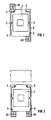
- FIG. 1 shows a sectional view of a housing 6 of a device, e.g. of a switching device, shown with a four-leg coil 1, which has a first winding end 2 and a second winding end 3. From the first winding end 2 there are electrical leads to two first slots 4 and from the second winding end 3 there are electrical leads to two second slots 5, each of which is provided on the outer wall of the housing 6. Slots 4 and 5 are designed differently to differentiate them.
- the device is connected via two special connection terminals A1 and A2 with a specific shape coding adapted to the slots 4, 5, so that the connector A1 can only be plugged into one of the slots 4 and the connector A2 only into one of the slots 5.
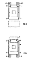
- the respective opposite free side can be used in a modular construction, e.g. to arrange a circuit breaker or an overload relay.
- the invention also offers the possibility of connecting the still free slots 4, 5 on one side of the device, e.g. a circuit block 7 to use.
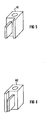
- FIG. 5,6 A possible design of the form-coded connections A1 and A2 is shown in FIG. 5,6.
- the parallelepiped-shaped terminals A1 and A2 differ only in that one side extends the right-hand side of the conductive centerpiece by a web (FIG. 5), while the other terminal has the side on the left opposite the conductive centerpiece (FIG 6) is.
Landscapes
- Engineering & Computer Science (AREA)
- Power Engineering (AREA)
- Physics & Mathematics (AREA)
- Electromagnetism (AREA)
- Details Of Connecting Devices For Male And Female Coupling (AREA)
- Connections Arranged To Contact A Plurality Of Conductors (AREA)
Abstract
Description
- Die Erfindung bezieht sich auf ein Schaltgerät, mit einer Vierbeinspule.
- Ein solches Gerät ist z.B. in der DE-OS 30 17 561 offenbart. Hier handelt es sich um ein elektromagnetisches Schaltgerät, z.B. ein Schütz mit benachbarten Anschlußebenen und mit einem Spulenkörper, der in der hinteren Anschlußebene liegende Ansätze zur Herstellung eines Diagonalanschlusses aufweist. Der Spulenkörper ist mit zwei in Richtung der benachbarten Anschlußebenen weisenden Vorsprüngen zur Aufnahme von einsteckbaren Anschlußklemmen versehen. Deren Anschlußschrauben liegen in der der hinteren Anschlußebene benachbarten Anschlußebene. Durch diese Ausführung sind bei dem Schaltgerät die Spulenanschlußmöglichkeiten auf einfache Weise, im Hinblick auf Zahl der Anschlußebenen, optimiert. Damit ist es möglich, bei nicht ausreichenden Platzverhältnissen im Bereich der hinteren Anschlußebene anstelle der hier liegenden Diagonalanschlüsse die im Bereich der benachbarten vorderen Ebene liegenden zwei zusätzlichen Anschlußmöglichkeiten zur Herstellung eines Vertikalanschlusses für die Spulen zu verwenden. Der hier eingesetzte Spulenkörper ermöglicht eine einfache Umrüstung des Schaltgeräts, in dem lediglich in diesen Anschlußklemmen eingesteckt bzw. herausgenommen werden, ohne daß ein neuer Spulenkörper erforderlich ist. Bei der hier beschriebenen Vierbeinspule ist zur Verhinderung von Kurzschlüssen beim Anschluß an eine Spannungsversorgung darauf zu achten, daß die Anschlüsse nicht versehentlich verwechselt werden.
- Die Erfindung zielt daher darauf ab, ein Gerät der obengenannten Art zu schaffen, bei dem der zum Kurzschluß führende fehlerhafte Anschluß vermieden wird. Dies wird bei dem obengenannten Gerät dadurch erreicht, daß dem ersten Wicklungsende der Vierbeinspule erste Steckplätze und ihrem zweiten Wicklungsende zweite Steckplätze zum elektrischen Anschluß an eine Versorgungsspannung zugeordnet sind, wobei die ersten Steckplätze verschieden von den zweiten Steckplätzen gestaltet sind, und das erste Wicklungsende durch Einschub einer ersten Anschlußklemme in einen der ersten Steckplätze und das zweite Wicklungsende durch Einschub einer zweiten Anschlußklemme in einen der zweiten Steckplätze kontaktiert ist. Weiterhin weist die erste Anschlußklemme eine dem ersten Steckplatz angepaßte Formkodierung und die zweite Anschlußklemme eine dem zweiten Steckplatz angepaßte Formkodierung auf. Weitere vorteilhafte Ausgestaltungen der Erfindung sind den Ansprüchen 2 bis 4 zu entnehmen.
- Die Geräte nach beanspruchter Bauart bieten individuelle Anschlußmöglichkeit beim Kunden. Die beliebige Umsteckbarkeit der Anschlüsse ermöglicht einen freiwählbaren Anschluß, z.B. von Leistungsschaltern oder Überlastrelais an ein Schaltgerät unter Berücksichtigung der speziellen räumlichen Verhältnisse. Freie Steckplätze an einer Seite des Geräts sind z.B. zum Anschluß eines Beschaltungsbausteins nutzbar. Durch die Formkodierung der Anschlußklemmen wird eine sonst mögliche Verwechslung sicher ausgeschlossen.
- Eine Ausführungsform der Erfindung wird im folgenden anhand einer Zeichnung näher erläutert. Es zeigen:
- FIG 1
- ein Gerät mit einer Vierbeinspule und steckbaren Anschlußklemmen im Schnitt,
- FIG 2,3
- ein Gerät mit Vierbeinspule und einseitig gesteckten Anschlußklemmen,
- FIG 4
- ein Gerät mit einseitig gesteckten Anschlußklemmen und einem zusätzlich angeschlossenen Beschaltungsbaustein,
- FIG 5,6
- formkodierte Anschlußklemmen.
- In FIG 1 ist in einer Schnittdarstellung andeutungsweise ein Gehäuse 6 eines Gerätes, z.B. eines Schaltgerätes, mit einer Vierbeinspule 1 dargestellt, die ein erstes Wicklungsende 2 und ein zweites Wicklungsende 3 aufweist. Vom ersten Wicklungsende 2 gibt es elektrische Zuleitungen zu zwei ersten Steckplätzen 4 und vom zweiten Wicklungsende 3 sind elektrische Zuleitungen zu zwei zweiten Steckplätzen 5 vorhanden, die jeweils an der Außenwand des Gehäuses 6 vorgesehen sind. Die Steckplätze 4 und 5 sind zu ihrer Unterscheidung verschieden gestaltet. Der Anschluß des Geräts erfolgt über zwei spezielle Anschlußklemmen A1 und A2 mit einer bestimmten an die Steckplätze 4, 5 angepaßten Formkodierung, so daß der Anschluß A1 nur in einen der Steckplätze 4 und der Anschluß A2 nur in einen der Steckplätze 5 steckbar ist. Damit ergibt sich neben der in FIG 1 dargestellten Anordnung der diagonal gegenüberliegenden Anschlüsse A1 und A2 die Möglichkeit, die Anschlüsse, wie in FIG 2,3 gezeigt, nur einseitig, z.B. an der Unterseite oder an der Oberseite des Geräts, einzustecken. Somit kann, wie in FIG 2,3 angedeutet, die jeweils gegenüberliegende freie Seite bei einer Modulbauweise dazu genutzt werden, z.B. einen Leistungsschalter oder ein Uberlastrelais anzuordnen.
- Gemäß FIG 4 bietet die Erfindung außerdem die Möglichkeit, die noch freien Steckplätze 4, 5 auf einer Seite des Geräts zum Anschluß, z.B. eines Beschaltungsbausteins 7, zu nutzen.
- In FIG 5,6 ist eine mögliche Gestaltungsform der formkodierten Anschlüsse A1 und A2 gezeigt. Die quaderförmigen Anschlußklemmen A1 und A2 unterscheiden sich lediglich dadurch, daß bei der einen die Seite rechtsseitig vom leitenden Mittelstück durch einen Steg verlängert ist (FIG 5), während es bei der anderen Anschlußklemme die gegenüber dem leitenden Mittelstück in der Ansicht links liegende Seite (FIG 6) ist.
Claims (4)
- Schaltgerät mit einer Vierbeinspule (1), derem ersten Wicklungsende (2) erste Steckplätze (4) und derem zweiten Wicklungsende (3) zweite Steckplätze (5) zum elektrischen Anschluß an eine Versorgungsspannung zugeordnet sind, wobei die ersten Steckplätze (4) verschieden von ihren zweiten Steckplätzen (5) gestaltet sind und das erste Wicklungsende (2) durch Einschub einer ersten Anschlußklemme (A1) in einen der ersten Steckplätze (4) und das zweite Wicklungsende (3) durch Einschub einer zweiten Anschlußklemme (A2) in einen der zweiten Steckplätze (5) kontaktiert ist und wobei die erste Anschlußklemme (A1) eine dem ersten Steckplatz (4) angepaßte Formkodierung und die zweite Anschlußklemme (A2) eine dem zweiten Steckplatz (5) angepaßte Formkodierung aufweist.
- Gerät nach Anspruch 1,
dadurch gekennzeichnet,
daß an zwei Seiten des Geräts jeweils mindestens ein erster (4) und ein zweiter Steckplatz (5) vorgesehen sind. - Gerät nach Anspruch 1 oder 2,
dadurch gekennzeichnet,
daß jeweils an der Ober- und Unterseite des Gerätes bezogen auf seine Einbaulage mindestens ein erster (4) und ein zweiter Steckplatz (5) vorgesehen sind. - Gerät nach einem der vorangehenden Ansprüche,
dadurch gekennzeichnet,
daß an einer Seite des Geräts über einen ersten (4) und einen zweiten Steckplatz (5) ein Beschaltungsbaustein (7) anschließbar ist.
Applications Claiming Priority (3)
| Application Number | Priority Date | Filing Date | Title |
|---|---|---|---|
| DE4322648 | 1993-07-07 | ||
| DE4322648A DE4322648C1 (de) | 1993-07-07 | 1993-07-07 | Gerät mit Vierbeinspule |
| PCT/DE1994/000713 WO1995002255A1 (de) | 1993-07-07 | 1994-06-22 | Gerät mit vierbeinspule |
Publications (2)
| Publication Number | Publication Date |
|---|---|
| EP0707740A1 EP0707740A1 (de) | 1996-04-24 |
| EP0707740B1 true EP0707740B1 (de) | 1996-11-27 |
Family
ID=6492200
Family Applications (1)
| Application Number | Title | Priority Date | Filing Date |
|---|---|---|---|
| EP94918293A Expired - Lifetime EP0707740B1 (de) | 1993-07-07 | 1994-06-22 | Gerät mit vierbeinspule |
Country Status (6)
| Country | Link |
|---|---|
| US (1) | US5724018A (de) |
| EP (1) | EP0707740B1 (de) |
| JP (1) | JPH09504405A (de) |
| CN (1) | CN1035738C (de) |
| DE (2) | DE4322648C1 (de) |
| WO (1) | WO1995002255A1 (de) |
Cited By (1)
| Publication number | Priority date | Publication date | Assignee | Title |
|---|---|---|---|---|
| EP1918958A1 (de) * | 2006-11-02 | 2008-05-07 | ABB France | Schaltschütz mit Modulanschluss zur Spule |
Families Citing this family (7)
| Publication number | Priority date | Publication date | Assignee | Title |
|---|---|---|---|---|
| EP0727802A3 (de) * | 1995-02-16 | 1997-12-10 | Rockwell Automation AG | Elektromagnetisches Schaltgerät, insbesondere Schütz |
| DE19814400C1 (de) * | 1998-03-31 | 1999-12-23 | Moeller Gmbh | Elektromagnetisches Schaltgerät mit mehrteiligem Gehäuse |
| DE19814432C1 (de) * | 1998-03-31 | 1999-12-23 | Moeller Gmbh | Elektromagnetisches Schaltgerät mit einem mehrteiligen Gehäuse |
| US7714292B2 (en) * | 2006-02-01 | 2010-05-11 | Koninklijke Philips Electronics N.V. | Geiger mode avalanche photodiode |
| GB2434925B (en) * | 2006-02-07 | 2010-08-18 | Motorola Inc | Electrical device with an I/O wiring interface |
| DE102007013052B3 (de) * | 2007-03-19 | 2008-09-04 | Siemens Ag | Elektromagnetisches Gerät mit verschiebbaren Anschlüssen |
| US20130200055A1 (en) * | 2012-02-02 | 2013-08-08 | Lincoln Global, Inc. | Power source and wire feeder matching |
Family Cites Families (5)
| Publication number | Priority date | Publication date | Assignee | Title |
|---|---|---|---|---|
| GB633394A (en) * | 1947-08-14 | 1949-12-12 | Crabtree & Co Ltd J A | Improvements in electromagnetic switches |
| DE3017561C2 (de) * | 1980-05-08 | 1986-07-03 | Licentia Patent-Verwaltungs-Gmbh, 6000 Frankfurt | Schaltgerät |
| DD201067A1 (de) * | 1981-11-20 | 1983-06-29 | Henry Baumruker | Spule fuer elektromagnetische schaltgeraete |
| WO1991018408A1 (de) * | 1990-05-14 | 1991-11-28 | Siemens Aktiengesellschaft | Elektromagnetisches schaltsystem und verfahren zu dessen herstellung |
| JPH06319054A (ja) * | 1993-05-07 | 1994-11-15 | Matsushita Electric Ind Co Ltd | フライバックトランス |
-
1993
- 1993-07-07 DE DE4322648A patent/DE4322648C1/de not_active Expired - Fee Related
-
1994
- 1994-06-22 WO PCT/DE1994/000713 patent/WO1995002255A1/de not_active Ceased
- 1994-06-22 JP JP6524675A patent/JPH09504405A/ja active Pending
- 1994-06-22 US US08/571,946 patent/US5724018A/en not_active Expired - Lifetime
- 1994-06-22 EP EP94918293A patent/EP0707740B1/de not_active Expired - Lifetime
- 1994-06-22 DE DE59401173T patent/DE59401173D1/de not_active Expired - Fee Related
- 1994-06-22 CN CN94192677A patent/CN1035738C/zh not_active Expired - Fee Related
Cited By (3)
| Publication number | Priority date | Publication date | Assignee | Title |
|---|---|---|---|---|
| EP1918958A1 (de) * | 2006-11-02 | 2008-05-07 | ABB France | Schaltschütz mit Modulanschluss zur Spule |
| FR2908233A1 (fr) * | 2006-11-02 | 2008-05-09 | Abb Entrelec Soc Par Actions S | Contacteur a raccordement modulaire de la bobine |
| US7679477B2 (en) | 2006-11-02 | 2010-03-16 | Abb France | Contactor with modular connection of the coil |
Also Published As
| Publication number | Publication date |
|---|---|
| CN1126527A (zh) | 1996-07-10 |
| US5724018A (en) | 1998-03-03 |
| JPH09504405A (ja) | 1997-04-28 |
| DE4322648C1 (de) | 1994-08-18 |
| CN1035738C (zh) | 1997-08-27 |
| DE59401173D1 (de) | 1997-01-09 |
| WO1995002255A1 (de) | 1995-01-19 |
| EP0707740A1 (de) | 1996-04-24 |
Similar Documents
| Publication | Publication Date | Title |
|---|---|---|
| AT399064B (de) | Elektrische schaltvorrichtung mit thermischem schutz | |
| DE69008139T2 (de) | Bauelementensatz zum gleizeitigen elektrischen Verbinden einer Mehrzahl von modularen Selbstschaltern. | |
| DE60037215T2 (de) | Elektrischer Jack-Steckverbinder mit wählbarer Anpassung | |
| DE2547344A1 (de) | Fehlerstromschutzschalter in steckdosenausfuehrung | |
| EP0707740B1 (de) | Gerät mit vierbeinspule | |
| DE9211314U1 (de) | Mehrpolige Anschlußklemme | |
| DE19939020A1 (de) | Elektromagnetisches Schaltschütz | |
| EP0079016B1 (de) | Steckverbindung mit schaltbarer Kontaktbrücke | |
| DE69420923T2 (de) | Differentialschutzblock mit Kabeldurchgang | |
| DE19703006C2 (de) | Steckfassung für Relais | |
| DE3438422A1 (de) | Elektrisches schaltgeraet | |
| EP0316259A2 (de) | Anschlussleiste aus mehreren Teilleisten | |
| EP0311732B1 (de) | Büromaschine, insbesondere Matrixdrucker | |
| DE2618288B2 (de) | Installations-Selbstschalter | |
| DE3620416C2 (de) | ||
| DE10011385A1 (de) | Einbaugerät für elektrische Niederspannungsinstallation | |
| EP0262554A2 (de) | Einrichtung zum Verbinden von Installationsgeräten mit Stromsammelschiene eines Grundsammelschienensystems | |
| DE2907207A1 (de) | Umschaltsteckverbindung | |
| DE19846219B4 (de) | Stromschalter | |
| DE102023117907B4 (de) | Geräteträger-modul und montagetafel-system mit einem solchen geräteträger-modul | |
| EP0595304B1 (de) | Schirmeinrichtung für rechteckige Kabelstecker | |
| DE9319716U1 (de) | Installationseinrichtung mit Einsätzen für Schalter- oder Steckkontaktelemente | |
| DE69310590T2 (de) | Schalttafel für Niederspannungsdrehstromszähler | |
| EP0432859B1 (de) | Kontaktvorrichtung zur lösbaren Aufnahme von Trennkontaktstücken eines mehrpoligen Schaltgerätes | |
| EP0656638A2 (de) | Lasttrennschalter |
Legal Events
| Date | Code | Title | Description |
|---|---|---|---|
| PUAI | Public reference made under article 153(3) epc to a published international application that has entered the european phase |
Free format text: ORIGINAL CODE: 0009012 |
|
| 17P | Request for examination filed |
Effective date: 19950724 |
|
| AK | Designated contracting states |
Kind code of ref document: A1 Designated state(s): CH DE FR GB IT LI SE |
|
| GRAG | Despatch of communication of intention to grant |
Free format text: ORIGINAL CODE: EPIDOS AGRA |
|
| GRAH | Despatch of communication of intention to grant a patent |
Free format text: ORIGINAL CODE: EPIDOS IGRA |
|
| 17Q | First examination report despatched |
Effective date: 19960507 |
|
| GRAH | Despatch of communication of intention to grant a patent |
Free format text: ORIGINAL CODE: EPIDOS IGRA |
|
| GRAA | (expected) grant |
Free format text: ORIGINAL CODE: 0009210 |
|
| AK | Designated contracting states |
Kind code of ref document: B1 Designated state(s): CH DE FR GB IT LI SE |
|
| PG25 | Lapsed in a contracting state [announced via postgrant information from national office to epo] |
Ref country code: IT Free format text: LAPSE BECAUSE OF FAILURE TO SUBMIT A TRANSLATION OF THE DESCRIPTION OR TO PAY THE FEE WITHIN THE PRESCRIBED TIME-LIMIT;WARNING: LAPSES OF ITALIAN PATENTS WITH EFFECTIVE DATE BEFORE 2007 MAY HAVE OCCURRED AT ANY TIME BEFORE 2007. THE CORRECT EFFECTIVE DATE MAY BE DIFFERENT FROM THE ONE RECORDED. Effective date: 19961127 |
|
| REG | Reference to a national code |
Ref country code: CH Ref legal event code: NV Representative=s name: SIEMENS SCHWEIZ AG |
|
| REF | Corresponds to: |
Ref document number: 59401173 Country of ref document: DE Date of ref document: 19970109 |
|
| ET | Fr: translation filed | ||
| GBT | Gb: translation of ep patent filed (gb section 77(6)(a)/1977) |
Effective date: 19970130 |
|
| PGFP | Annual fee paid to national office [announced via postgrant information from national office to epo] |
Ref country code: SE Payment date: 19970612 Year of fee payment: 4 |
|
| PGFP | Annual fee paid to national office [announced via postgrant information from national office to epo] |
Ref country code: CH Payment date: 19970912 Year of fee payment: 4 |
|
| PLBE | No opposition filed within time limit |
Free format text: ORIGINAL CODE: 0009261 |
|
| STAA | Information on the status of an ep patent application or granted ep patent |
Free format text: STATUS: NO OPPOSITION FILED WITHIN TIME LIMIT |
|
| 26N | No opposition filed | ||
| PG25 | Lapsed in a contracting state [announced via postgrant information from national office to epo] |
Ref country code: GB Free format text: LAPSE BECAUSE OF NON-PAYMENT OF DUE FEES Effective date: 19980622 |
|
| PG25 | Lapsed in a contracting state [announced via postgrant information from national office to epo] |
Ref country code: SE Free format text: LAPSE BECAUSE OF NON-PAYMENT OF DUE FEES Effective date: 19980623 |
|
| PG25 | Lapsed in a contracting state [announced via postgrant information from national office to epo] |
Ref country code: LI Free format text: LAPSE BECAUSE OF NON-PAYMENT OF DUE FEES Effective date: 19980630 Ref country code: CH Free format text: LAPSE BECAUSE OF NON-PAYMENT OF DUE FEES Effective date: 19980630 |
|
| GBPC | Gb: european patent ceased through non-payment of renewal fee |
Effective date: 19980622 |
|
| REG | Reference to a national code |
Ref country code: CH Ref legal event code: PL |
|
| EUG | Se: european patent has lapsed |
Ref document number: 94918293.5 |
|
| PGFP | Annual fee paid to national office [announced via postgrant information from national office to epo] |
Ref country code: FR Payment date: 20090616 Year of fee payment: 16 |
|
| PGFP | Annual fee paid to national office [announced via postgrant information from national office to epo] |
Ref country code: DE Payment date: 20090821 Year of fee payment: 16 |
|
| REG | Reference to a national code |
Ref country code: FR Ref legal event code: ST Effective date: 20110228 |
|
| PG25 | Lapsed in a contracting state [announced via postgrant information from national office to epo] |
Ref country code: DE Free format text: LAPSE BECAUSE OF NON-PAYMENT OF DUE FEES Effective date: 20110101 |
|
| PG25 | Lapsed in a contracting state [announced via postgrant information from national office to epo] |
Ref country code: FR Free format text: LAPSE BECAUSE OF NON-PAYMENT OF DUE FEES Effective date: 20100630 |