EP0707740B1 - Appareil avec bobine a quatre branches - Google Patents
Appareil avec bobine a quatre branches Download PDFInfo
- Publication number
- EP0707740B1 EP0707740B1 EP94918293A EP94918293A EP0707740B1 EP 0707740 B1 EP0707740 B1 EP 0707740B1 EP 94918293 A EP94918293 A EP 94918293A EP 94918293 A EP94918293 A EP 94918293A EP 0707740 B1 EP0707740 B1 EP 0707740B1
- Authority
- EP
- European Patent Office
- Prior art keywords
- plug
- location
- connection
- winding end
- locations
- Prior art date
- Legal status (The legal status is an assumption and is not a legal conclusion. Google has not performed a legal analysis and makes no representation as to the accuracy of the status listed.)
- Expired - Lifetime
Links
- 238000004804 winding Methods 0.000 claims abstract description 13
- 238000010276 construction Methods 0.000 abstract description 2
- 238000013459 approach Methods 0.000 description 1
Images
Classifications
-
- H—ELECTRICITY
- H01—ELECTRIC ELEMENTS
- H01H—ELECTRIC SWITCHES; RELAYS; SELECTORS; EMERGENCY PROTECTIVE DEVICES
- H01H50/00—Details of electromagnetic relays
- H01H50/44—Magnetic coils or windings
- H01H50/443—Connections to coils
-
- H—ELECTRICITY
- H01—ELECTRIC ELEMENTS
- H01F—MAGNETS; INDUCTANCES; TRANSFORMERS; SELECTION OF MATERIALS FOR THEIR MAGNETIC PROPERTIES
- H01F5/00—Coils
- H01F5/04—Arrangements of electric connections to coils, e.g. leads
-
- H—ELECTRICITY
- H01—ELECTRIC ELEMENTS
- H01H—ELECTRIC SWITCHES; RELAYS; SELECTORS; EMERGENCY PROTECTIVE DEVICES
- H01H11/00—Apparatus or processes specially adapted for the manufacture of electric switches
- H01H11/0006—Apparatus or processes specially adapted for the manufacture of electric switches for converting electric switches
- H01H11/0031—Apparatus or processes specially adapted for the manufacture of electric switches for converting electric switches for allowing different types or orientation of connections to contacts
-
- H—ELECTRICITY
- H01—ELECTRIC ELEMENTS
- H01H—ELECTRIC SWITCHES; RELAYS; SELECTORS; EMERGENCY PROTECTIVE DEVICES
- H01H50/00—Details of electromagnetic relays
- H01H50/02—Bases; Casings; Covers
- H01H50/021—Bases; Casings; Covers structurally combining a relay and an electronic component, e.g. varistor, RC circuit
Definitions
- the invention relates to a switching device with a four-legged coil.
- Such a device is e.g. disclosed in DE-OS 30 17 561.
- This is an electromagnetic switching device, e.g. a contactor with adjacent connection levels and with a coil body, which has approaches in the rear connection level for producing a diagonal connection.
- the coil body is provided with two projections pointing in the direction of the adjacent connection planes for receiving plug-in connection terminals. Their connection screws are in the connection level adjacent to the rear connection level.
- This design optimizes the coil connection options in the switching device in a simple manner with regard to the number of connection levels. This makes it possible, if there is insufficient space in the area of the rear connection level, instead of the diagonal connections located here, to use the two additional connection options located in the area of the adjacent front level for producing a vertical connection for the coils.
- the coil former used here enables the switching device to be easily converted by simply plugging in and out of these connecting terminals without the need for a new coil former.
- care must be taken that the connections are not accidentally mixed up.
- the invention therefore aims to provide a device of the type mentioned above, in which the faulty connection leading to a short circuit is avoided.
- This will be the case with the The above device is achieved in that the first winding end of the four-legged coil is assigned first slots and its second winding end has second slots for electrical connection to a supply voltage, the first slots being designed differently from the second slots, and the first winding end by inserting a first terminal in one of the first slots and the second winding end is contacted by inserting a second terminal into one of the second slots.
- the first connection terminal has a shape coding adapted to the first slot and the second connection terminal has a shape coding adapted to the second slot.
- the devices of the claimed design offer individual connection options at the customer.
- the arbitrary reversibility of the connections enables a freely selectable connection, e.g. from circuit breakers or overload relays to a switching device taking into account the special spatial conditions.
- Free slots on one side of the device are e.g. can be used to connect a circuit block.
- the form coding of the connection terminals reliably prevents any other possible confusion.
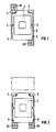
- FIG. 1 shows a sectional view of a housing 6 of a device, e.g. of a switching device, shown with a four-leg coil 1, which has a first winding end 2 and a second winding end 3. From the first winding end 2 there are electrical leads to two first slots 4 and from the second winding end 3 there are electrical leads to two second slots 5, each of which is provided on the outer wall of the housing 6. Slots 4 and 5 are designed differently to differentiate them.
- the device is connected via two special connection terminals A1 and A2 with a specific shape coding adapted to the slots 4, 5, so that the connector A1 can only be plugged into one of the slots 4 and the connector A2 only into one of the slots 5.
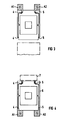
- the respective opposite free side can be used in a modular construction, e.g. to arrange a circuit breaker or an overload relay.
- the invention also offers the possibility of connecting the still free slots 4, 5 on one side of the device, e.g. a circuit block 7 to use.
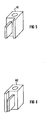
- FIG. 5,6 A possible design of the form-coded connections A1 and A2 is shown in FIG. 5,6.
- the parallelepiped-shaped terminals A1 and A2 differ only in that one side extends the right-hand side of the conductive centerpiece by a web (FIG. 5), while the other terminal has the side on the left opposite the conductive centerpiece (FIG 6) is.
Landscapes
- Engineering & Computer Science (AREA)
- Power Engineering (AREA)
- Physics & Mathematics (AREA)
- Electromagnetism (AREA)
- Details Of Connecting Devices For Male And Female Coupling (AREA)
- Connections Arranged To Contact A Plurality Of Conductors (AREA)
Abstract
Claims (4)
- Appareil de coupure comportant une bobine (1) à quatre branches à la première extrémité (2) d'enroulement de laquelle sont associés des premiers emplacements (4) d'enfichage et à la deuxième extrémité (3) d'enroulement de laquelle sont associés des deuxièmes emplacements (5) d'enfichage pour le raccordement électrique à une tension d'alimentation, les premiers emplacements (4) d'enfichage étant agencés différemment de ses deuxièmes emplacements (5) d'enfichage et la première extrémité (2) d'enroulement étant mise en contact en enfonçant une première borne (A1) de raccordement dans un des premiers emplacements (4) d'enfichage et la deuxième extrémité (3) d'enroulement étant mise en contact en enfonçant une deuxième borne (A2) de raccordement dans un des deuxièmes emplacements (5) d'enfichage, et la première borne (A1) de raccordement comporte un codage de forme adapté au premier emplacement (4) d'enfichage et la deuxième borne (A2) de raccordement comporte un codage de forme adapté au deuxième emplacement (5) d'enfichage.
- Appareil suivant la revendication 1, caractérisé en ce qu'il est prévu de deux côtés de l'appareil au moins un premier emplacement (4) d'enfichage et un deuxième emplacement (5) d'enfichage.
- Appareil suivant la revendication 1 ou 2, caractérisé en ce qu'il est prévu du côté supérieur et du côté inférieur de l'appareil rapporté à sa position de montage au moins un premier emplacement (4) d'enfichage et un deuxième emplacement (5) d'enfichage.
- Appareil suivant une des revendications précédentes, caractérisé en ce qu'un module (7) de câblage peut être raccordé d'un côté de l'appareil par l'intermédiaire d'un premier emplacement (4) d'enfichage et d'un deuxième emplacement (5) d'enfichage.
Applications Claiming Priority (3)
| Application Number | Priority Date | Filing Date | Title |
|---|---|---|---|
| DE4322648 | 1993-07-07 | ||
| DE4322648A DE4322648C1 (de) | 1993-07-07 | 1993-07-07 | Gerät mit Vierbeinspule |
| PCT/DE1994/000713 WO1995002255A1 (fr) | 1993-07-07 | 1994-06-22 | Appareil avec bobine a quatre branches |
Publications (2)
| Publication Number | Publication Date |
|---|---|
| EP0707740A1 EP0707740A1 (fr) | 1996-04-24 |
| EP0707740B1 true EP0707740B1 (fr) | 1996-11-27 |
Family
ID=6492200
Family Applications (1)
| Application Number | Title | Priority Date | Filing Date |
|---|---|---|---|
| EP94918293A Expired - Lifetime EP0707740B1 (fr) | 1993-07-07 | 1994-06-22 | Appareil avec bobine a quatre branches |
Country Status (6)
| Country | Link |
|---|---|
| US (1) | US5724018A (fr) |
| EP (1) | EP0707740B1 (fr) |
| JP (1) | JPH09504405A (fr) |
| CN (1) | CN1035738C (fr) |
| DE (2) | DE4322648C1 (fr) |
| WO (1) | WO1995002255A1 (fr) |
Cited By (1)
| Publication number | Priority date | Publication date | Assignee | Title |
|---|---|---|---|---|
| EP1918958A1 (fr) * | 2006-11-02 | 2008-05-07 | ABB France | Contacteur à raccordement modulaire de la bobine |
Families Citing this family (7)
| Publication number | Priority date | Publication date | Assignee | Title |
|---|---|---|---|---|
| EP0727802A3 (fr) * | 1995-02-16 | 1997-12-10 | Rockwell Automation AG | Dispositif de commutation électromagnétique, en particulier contacteur |
| DE19814400C1 (de) * | 1998-03-31 | 1999-12-23 | Moeller Gmbh | Elektromagnetisches Schaltgerät mit mehrteiligem Gehäuse |
| DE19814432C1 (de) * | 1998-03-31 | 1999-12-23 | Moeller Gmbh | Elektromagnetisches Schaltgerät mit einem mehrteiligen Gehäuse |
| US7714292B2 (en) * | 2006-02-01 | 2010-05-11 | Koninklijke Philips Electronics N.V. | Geiger mode avalanche photodiode |
| GB2434925B (en) * | 2006-02-07 | 2010-08-18 | Motorola Inc | Electrical device with an I/O wiring interface |
| DE102007013052B3 (de) * | 2007-03-19 | 2008-09-04 | Siemens Ag | Elektromagnetisches Gerät mit verschiebbaren Anschlüssen |
| US20130200055A1 (en) * | 2012-02-02 | 2013-08-08 | Lincoln Global, Inc. | Power source and wire feeder matching |
Family Cites Families (5)
| Publication number | Priority date | Publication date | Assignee | Title |
|---|---|---|---|---|
| GB633394A (en) * | 1947-08-14 | 1949-12-12 | Crabtree & Co Ltd J A | Improvements in electromagnetic switches |
| DE3017561C2 (de) * | 1980-05-08 | 1986-07-03 | Licentia Patent-Verwaltungs-Gmbh, 6000 Frankfurt | Schaltgerät |
| DD201067A1 (de) * | 1981-11-20 | 1983-06-29 | Henry Baumruker | Spule fuer elektromagnetische schaltgeraete |
| WO1991018408A1 (fr) * | 1990-05-14 | 1991-11-28 | Siemens Aktiengesellschaft | Systeme commutateur electromagnetique et son procede de production |
| JPH06319054A (ja) * | 1993-05-07 | 1994-11-15 | Matsushita Electric Ind Co Ltd | フライバックトランス |
-
1993
- 1993-07-07 DE DE4322648A patent/DE4322648C1/de not_active Expired - Fee Related
-
1994
- 1994-06-22 WO PCT/DE1994/000713 patent/WO1995002255A1/fr not_active Ceased
- 1994-06-22 JP JP6524675A patent/JPH09504405A/ja active Pending
- 1994-06-22 US US08/571,946 patent/US5724018A/en not_active Expired - Lifetime
- 1994-06-22 EP EP94918293A patent/EP0707740B1/fr not_active Expired - Lifetime
- 1994-06-22 DE DE59401173T patent/DE59401173D1/de not_active Expired - Fee Related
- 1994-06-22 CN CN94192677A patent/CN1035738C/zh not_active Expired - Fee Related
Cited By (3)
| Publication number | Priority date | Publication date | Assignee | Title |
|---|---|---|---|---|
| EP1918958A1 (fr) * | 2006-11-02 | 2008-05-07 | ABB France | Contacteur à raccordement modulaire de la bobine |
| FR2908233A1 (fr) * | 2006-11-02 | 2008-05-09 | Abb Entrelec Soc Par Actions S | Contacteur a raccordement modulaire de la bobine |
| US7679477B2 (en) | 2006-11-02 | 2010-03-16 | Abb France | Contactor with modular connection of the coil |
Also Published As
| Publication number | Publication date |
|---|---|
| CN1126527A (zh) | 1996-07-10 |
| US5724018A (en) | 1998-03-03 |
| JPH09504405A (ja) | 1997-04-28 |
| DE4322648C1 (de) | 1994-08-18 |
| CN1035738C (zh) | 1997-08-27 |
| DE59401173D1 (de) | 1997-01-09 |
| WO1995002255A1 (fr) | 1995-01-19 |
| EP0707740A1 (fr) | 1996-04-24 |
Similar Documents
| Publication | Publication Date | Title |
|---|---|---|
| AT399064B (de) | Elektrische schaltvorrichtung mit thermischem schutz | |
| DE69008139T2 (de) | Bauelementensatz zum gleizeitigen elektrischen Verbinden einer Mehrzahl von modularen Selbstschaltern. | |
| DE60037215T2 (de) | Elektrischer Jack-Steckverbinder mit wählbarer Anpassung | |
| DE2547344A1 (de) | Fehlerstromschutzschalter in steckdosenausfuehrung | |
| EP0707740B1 (fr) | Appareil avec bobine a quatre branches | |
| DE9211314U1 (de) | Mehrpolige Anschlußklemme | |
| DE19939020A1 (de) | Elektromagnetisches Schaltschütz | |
| EP0079016B1 (fr) | Connexion enfichable avec pont de contact interrupteur | |
| DE69420923T2 (de) | Differentialschutzblock mit Kabeldurchgang | |
| DE19703006C2 (de) | Steckfassung für Relais | |
| DE3438422A1 (de) | Elektrisches schaltgeraet | |
| EP0316259A2 (fr) | Bloc de connexion formé de plusieurs sous-blocs | |
| EP0311732B1 (fr) | Appareil de bureau, notamment imprimante à matrice | |
| DE2618288B2 (de) | Installations-Selbstschalter | |
| DE3620416C2 (fr) | ||
| DE10011385A1 (de) | Einbaugerät für elektrische Niederspannungsinstallation | |
| EP0262554A2 (fr) | Dispositif de connexion d'appareils d'installation aux barres de courant d'un système de base de barres omnibus | |
| DE2907207A1 (de) | Umschaltsteckverbindung | |
| DE19846219B4 (de) | Stromschalter | |
| DE102023117907B4 (de) | Geräteträger-modul und montagetafel-system mit einem solchen geräteträger-modul | |
| EP0595304B1 (fr) | Dispositif de blindage pour connecteur de câble rectangulaire | |
| DE9319716U1 (de) | Installationseinrichtung mit Einsätzen für Schalter- oder Steckkontaktelemente | |
| DE69310590T2 (de) | Schalttafel für Niederspannungsdrehstromszähler | |
| EP0432859B1 (fr) | Dispositif de contact apte à recevoir des contacts de coupure amovibles d'un appareil de commutation multipolaire | |
| EP0656638A2 (fr) | Disjoncteur sectionneur |
Legal Events
| Date | Code | Title | Description |
|---|---|---|---|
| PUAI | Public reference made under article 153(3) epc to a published international application that has entered the european phase |
Free format text: ORIGINAL CODE: 0009012 |
|
| 17P | Request for examination filed |
Effective date: 19950724 |
|
| AK | Designated contracting states |
Kind code of ref document: A1 Designated state(s): CH DE FR GB IT LI SE |
|
| GRAG | Despatch of communication of intention to grant |
Free format text: ORIGINAL CODE: EPIDOS AGRA |
|
| GRAH | Despatch of communication of intention to grant a patent |
Free format text: ORIGINAL CODE: EPIDOS IGRA |
|
| 17Q | First examination report despatched |
Effective date: 19960507 |
|
| GRAH | Despatch of communication of intention to grant a patent |
Free format text: ORIGINAL CODE: EPIDOS IGRA |
|
| GRAA | (expected) grant |
Free format text: ORIGINAL CODE: 0009210 |
|
| AK | Designated contracting states |
Kind code of ref document: B1 Designated state(s): CH DE FR GB IT LI SE |
|
| PG25 | Lapsed in a contracting state [announced via postgrant information from national office to epo] |
Ref country code: IT Free format text: LAPSE BECAUSE OF FAILURE TO SUBMIT A TRANSLATION OF THE DESCRIPTION OR TO PAY THE FEE WITHIN THE PRESCRIBED TIME-LIMIT;WARNING: LAPSES OF ITALIAN PATENTS WITH EFFECTIVE DATE BEFORE 2007 MAY HAVE OCCURRED AT ANY TIME BEFORE 2007. THE CORRECT EFFECTIVE DATE MAY BE DIFFERENT FROM THE ONE RECORDED. Effective date: 19961127 |
|
| REG | Reference to a national code |
Ref country code: CH Ref legal event code: NV Representative=s name: SIEMENS SCHWEIZ AG |
|
| REF | Corresponds to: |
Ref document number: 59401173 Country of ref document: DE Date of ref document: 19970109 |
|
| ET | Fr: translation filed | ||
| GBT | Gb: translation of ep patent filed (gb section 77(6)(a)/1977) |
Effective date: 19970130 |
|
| PGFP | Annual fee paid to national office [announced via postgrant information from national office to epo] |
Ref country code: SE Payment date: 19970612 Year of fee payment: 4 |
|
| PGFP | Annual fee paid to national office [announced via postgrant information from national office to epo] |
Ref country code: CH Payment date: 19970912 Year of fee payment: 4 |
|
| PLBE | No opposition filed within time limit |
Free format text: ORIGINAL CODE: 0009261 |
|
| STAA | Information on the status of an ep patent application or granted ep patent |
Free format text: STATUS: NO OPPOSITION FILED WITHIN TIME LIMIT |
|
| 26N | No opposition filed | ||
| PG25 | Lapsed in a contracting state [announced via postgrant information from national office to epo] |
Ref country code: GB Free format text: LAPSE BECAUSE OF NON-PAYMENT OF DUE FEES Effective date: 19980622 |
|
| PG25 | Lapsed in a contracting state [announced via postgrant information from national office to epo] |
Ref country code: SE Free format text: LAPSE BECAUSE OF NON-PAYMENT OF DUE FEES Effective date: 19980623 |
|
| PG25 | Lapsed in a contracting state [announced via postgrant information from national office to epo] |
Ref country code: LI Free format text: LAPSE BECAUSE OF NON-PAYMENT OF DUE FEES Effective date: 19980630 Ref country code: CH Free format text: LAPSE BECAUSE OF NON-PAYMENT OF DUE FEES Effective date: 19980630 |
|
| GBPC | Gb: european patent ceased through non-payment of renewal fee |
Effective date: 19980622 |
|
| REG | Reference to a national code |
Ref country code: CH Ref legal event code: PL |
|
| EUG | Se: european patent has lapsed |
Ref document number: 94918293.5 |
|
| PGFP | Annual fee paid to national office [announced via postgrant information from national office to epo] |
Ref country code: FR Payment date: 20090616 Year of fee payment: 16 |
|
| PGFP | Annual fee paid to national office [announced via postgrant information from national office to epo] |
Ref country code: DE Payment date: 20090821 Year of fee payment: 16 |
|
| REG | Reference to a national code |
Ref country code: FR Ref legal event code: ST Effective date: 20110228 |
|
| PG25 | Lapsed in a contracting state [announced via postgrant information from national office to epo] |
Ref country code: DE Free format text: LAPSE BECAUSE OF NON-PAYMENT OF DUE FEES Effective date: 20110101 |
|
| PG25 | Lapsed in a contracting state [announced via postgrant information from national office to epo] |
Ref country code: FR Free format text: LAPSE BECAUSE OF NON-PAYMENT OF DUE FEES Effective date: 20100630 |