EP0707963B1 - Tintenstrahlkopf, Tintenstrahlkopfkassette und Tintenstrahlapparat - Google Patents
Tintenstrahlkopf, Tintenstrahlkopfkassette und Tintenstrahlapparat Download PDFInfo
- Publication number
- EP0707963B1 EP0707963B1 EP95116587A EP95116587A EP0707963B1 EP 0707963 B1 EP0707963 B1 EP 0707963B1 EP 95116587 A EP95116587 A EP 95116587A EP 95116587 A EP95116587 A EP 95116587A EP 0707963 B1 EP0707963 B1 EP 0707963B1
- Authority
- EP
- European Patent Office
- Prior art keywords
- ink jet
- ink
- jet head
- heat generating
- ejection
- Prior art date
- Legal status (The legal status is an assumption and is not a legal conclusion. Google has not performed a legal analysis and makes no representation as to the accuracy of the status listed.)
- Expired - Lifetime
Links
- 239000000758 substrate Substances 0.000 claims description 31
- 239000007788 liquid Substances 0.000 claims description 11
- 239000000463 material Substances 0.000 claims description 6
- 238000010276 construction Methods 0.000 description 22
- 238000009826 distribution Methods 0.000 description 11
- 230000000694 effects Effects 0.000 description 11
- 238000010438 heat treatment Methods 0.000 description 11
- 230000006870 function Effects 0.000 description 7
- 230000009467 reduction Effects 0.000 description 7
- 230000006866 deterioration Effects 0.000 description 6
- 230000008859 change Effects 0.000 description 4
- 238000004140 cleaning Methods 0.000 description 4
- 230000003247 decreasing effect Effects 0.000 description 4
- 238000009413 insulation Methods 0.000 description 4
- XUIMIQQOPSSXEZ-UHFFFAOYSA-N Silicon Chemical compound [Si] XUIMIQQOPSSXEZ-UHFFFAOYSA-N 0.000 description 3
- 238000009825 accumulation Methods 0.000 description 3
- 230000007423 decrease Effects 0.000 description 3
- 238000000034 method Methods 0.000 description 3
- 230000005855 radiation Effects 0.000 description 3
- 238000011084 recovery Methods 0.000 description 3
- 229910052710 silicon Inorganic materials 0.000 description 3
- 239000010703 silicon Substances 0.000 description 3
- XAGFODPZIPBFFR-UHFFFAOYSA-N aluminium Chemical compound [Al] XAGFODPZIPBFFR-UHFFFAOYSA-N 0.000 description 2
- 229910052782 aluminium Inorganic materials 0.000 description 2
- 239000010408 film Substances 0.000 description 2
- 230000020169 heat generation Effects 0.000 description 2
- 230000006872 improvement Effects 0.000 description 2
- 238000004519 manufacturing process Methods 0.000 description 2
- 239000011159 matrix material Substances 0.000 description 2
- 238000012986 modification Methods 0.000 description 2
- 230000004048 modification Effects 0.000 description 2
- 230000036278 prepulse Effects 0.000 description 2
- 239000010409 thin film Substances 0.000 description 2
- 238000012546 transfer Methods 0.000 description 2
- 230000005540 biological transmission Effects 0.000 description 1
- 239000013078 crystal Substances 0.000 description 1
- 230000010365 information processing Effects 0.000 description 1
- 238000002347 injection Methods 0.000 description 1
- 239000007924 injection Substances 0.000 description 1
- 238000011835 investigation Methods 0.000 description 1
- 230000007774 longterm Effects 0.000 description 1
- 238000005457 optimization Methods 0.000 description 1
- 230000010355 oscillation Effects 0.000 description 1
- 230000008569 process Effects 0.000 description 1
- 230000000717 retained effect Effects 0.000 description 1
- 230000002441 reversible effect Effects 0.000 description 1
- 239000004065 semiconductor Substances 0.000 description 1
- 230000035939 shock Effects 0.000 description 1
- 238000004904 shortening Methods 0.000 description 1
- 230000006641 stabilisation Effects 0.000 description 1
- 238000011105 stabilization Methods 0.000 description 1
- 239000004753 textile Substances 0.000 description 1
- -1 thread Substances 0.000 description 1
Images


Classifications
-
- B—PERFORMING OPERATIONS; TRANSPORTING
- B41—PRINTING; LINING MACHINES; TYPEWRITERS; STAMPS
- B41J—TYPEWRITERS; SELECTIVE PRINTING MECHANISMS, i.e. MECHANISMS PRINTING OTHERWISE THAN FROM A FORME; CORRECTION OF TYPOGRAPHICAL ERRORS
- B41J2/00—Typewriters or selective printing mechanisms characterised by the printing or marking process for which they are designed
- B41J2/005—Typewriters or selective printing mechanisms characterised by the printing or marking process for which they are designed characterised by bringing liquid or particles selectively into contact with a printing material
- B41J2/01—Ink jet
- B41J2/015—Ink jet characterised by the jet generation process
- B41J2/04—Ink jet characterised by the jet generation process generating single droplets or particles on demand
- B41J2/045—Ink jet characterised by the jet generation process generating single droplets or particles on demand by pressure, e.g. electromechanical transducers
- B41J2/04501—Control methods or devices therefor, e.g. driver circuits, control circuits
- B41J2/04541—Specific driving circuit
-
- B—PERFORMING OPERATIONS; TRANSPORTING
- B41—PRINTING; LINING MACHINES; TYPEWRITERS; STAMPS
- B41J—TYPEWRITERS; SELECTIVE PRINTING MECHANISMS, i.e. MECHANISMS PRINTING OTHERWISE THAN FROM A FORME; CORRECTION OF TYPOGRAPHICAL ERRORS
- B41J2/00—Typewriters or selective printing mechanisms characterised by the printing or marking process for which they are designed
- B41J2/005—Typewriters or selective printing mechanisms characterised by the printing or marking process for which they are designed characterised by bringing liquid or particles selectively into contact with a printing material
- B41J2/01—Ink jet
- B41J2/015—Ink jet characterised by the jet generation process
- B41J2/04—Ink jet characterised by the jet generation process generating single droplets or particles on demand
- B41J2/045—Ink jet characterised by the jet generation process generating single droplets or particles on demand by pressure, e.g. electromechanical transducers
- B41J2/04501—Control methods or devices therefor, e.g. driver circuits, control circuits
- B41J2/04543—Block driving
-
- B—PERFORMING OPERATIONS; TRANSPORTING
- B41—PRINTING; LINING MACHINES; TYPEWRITERS; STAMPS
- B41J—TYPEWRITERS; SELECTIVE PRINTING MECHANISMS, i.e. MECHANISMS PRINTING OTHERWISE THAN FROM A FORME; CORRECTION OF TYPOGRAPHICAL ERRORS
- B41J2/00—Typewriters or selective printing mechanisms characterised by the printing or marking process for which they are designed
- B41J2/005—Typewriters or selective printing mechanisms characterised by the printing or marking process for which they are designed characterised by bringing liquid or particles selectively into contact with a printing material
- B41J2/01—Ink jet
- B41J2/015—Ink jet characterised by the jet generation process
- B41J2/04—Ink jet characterised by the jet generation process generating single droplets or particles on demand
- B41J2/045—Ink jet characterised by the jet generation process generating single droplets or particles on demand by pressure, e.g. electromechanical transducers
- B41J2/04501—Control methods or devices therefor, e.g. driver circuits, control circuits
- B41J2/04553—Control methods or devices therefor, e.g. driver circuits, control circuits detecting ambient temperature
-
- B—PERFORMING OPERATIONS; TRANSPORTING
- B41—PRINTING; LINING MACHINES; TYPEWRITERS; STAMPS
- B41J—TYPEWRITERS; SELECTIVE PRINTING MECHANISMS, i.e. MECHANISMS PRINTING OTHERWISE THAN FROM A FORME; CORRECTION OF TYPOGRAPHICAL ERRORS
- B41J2/00—Typewriters or selective printing mechanisms characterised by the printing or marking process for which they are designed
- B41J2/005—Typewriters or selective printing mechanisms characterised by the printing or marking process for which they are designed characterised by bringing liquid or particles selectively into contact with a printing material
- B41J2/01—Ink jet
- B41J2/015—Ink jet characterised by the jet generation process
- B41J2/04—Ink jet characterised by the jet generation process generating single droplets or particles on demand
- B41J2/045—Ink jet characterised by the jet generation process generating single droplets or particles on demand by pressure, e.g. electromechanical transducers
- B41J2/04501—Control methods or devices therefor, e.g. driver circuits, control circuits
- B41J2/04563—Control methods or devices therefor, e.g. driver circuits, control circuits detecting head temperature; Ink temperature
-
- B—PERFORMING OPERATIONS; TRANSPORTING
- B41—PRINTING; LINING MACHINES; TYPEWRITERS; STAMPS
- B41J—TYPEWRITERS; SELECTIVE PRINTING MECHANISMS, i.e. MECHANISMS PRINTING OTHERWISE THAN FROM A FORME; CORRECTION OF TYPOGRAPHICAL ERRORS
- B41J2/00—Typewriters or selective printing mechanisms characterised by the printing or marking process for which they are designed
- B41J2/005—Typewriters or selective printing mechanisms characterised by the printing or marking process for which they are designed characterised by bringing liquid or particles selectively into contact with a printing material
- B41J2/01—Ink jet
- B41J2/015—Ink jet characterised by the jet generation process
- B41J2/04—Ink jet characterised by the jet generation process generating single droplets or particles on demand
- B41J2/045—Ink jet characterised by the jet generation process generating single droplets or particles on demand by pressure, e.g. electromechanical transducers
- B41J2/04501—Control methods or devices therefor, e.g. driver circuits, control circuits
- B41J2/04571—Control methods or devices therefor, e.g. driver circuits, control circuits detecting viscosity
-
- B—PERFORMING OPERATIONS; TRANSPORTING
- B41—PRINTING; LINING MACHINES; TYPEWRITERS; STAMPS
- B41J—TYPEWRITERS; SELECTIVE PRINTING MECHANISMS, i.e. MECHANISMS PRINTING OTHERWISE THAN FROM A FORME; CORRECTION OF TYPOGRAPHICAL ERRORS
- B41J2/00—Typewriters or selective printing mechanisms characterised by the printing or marking process for which they are designed
- B41J2/005—Typewriters or selective printing mechanisms characterised by the printing or marking process for which they are designed characterised by bringing liquid or particles selectively into contact with a printing material
- B41J2/01—Ink jet
- B41J2/015—Ink jet characterised by the jet generation process
- B41J2/04—Ink jet characterised by the jet generation process generating single droplets or particles on demand
- B41J2/045—Ink jet characterised by the jet generation process generating single droplets or particles on demand by pressure, e.g. electromechanical transducers
- B41J2/04501—Control methods or devices therefor, e.g. driver circuits, control circuits
- B41J2/0458—Control methods or devices therefor, e.g. driver circuits, control circuits controlling heads based on heating elements forming bubbles
-
- B—PERFORMING OPERATIONS; TRANSPORTING
- B41—PRINTING; LINING MACHINES; TYPEWRITERS; STAMPS
- B41J—TYPEWRITERS; SELECTIVE PRINTING MECHANISMS, i.e. MECHANISMS PRINTING OTHERWISE THAN FROM A FORME; CORRECTION OF TYPOGRAPHICAL ERRORS
- B41J2/00—Typewriters or selective printing mechanisms characterised by the printing or marking process for which they are designed
- B41J2/005—Typewriters or selective printing mechanisms characterised by the printing or marking process for which they are designed characterised by bringing liquid or particles selectively into contact with a printing material
- B41J2/01—Ink jet
- B41J2/135—Nozzles
- B41J2/14—Structure thereof only for on-demand ink jet heads
- B41J2/14016—Structure of bubble jet print heads
- B41J2/14032—Structure of the pressure chamber
- B41J2/14056—Plural heating elements per ink chamber
-
- B—PERFORMING OPERATIONS; TRANSPORTING
- B41—PRINTING; LINING MACHINES; TYPEWRITERS; STAMPS
- B41J—TYPEWRITERS; SELECTIVE PRINTING MECHANISMS, i.e. MECHANISMS PRINTING OTHERWISE THAN FROM A FORME; CORRECTION OF TYPOGRAPHICAL ERRORS
- B41J2/00—Typewriters or selective printing mechanisms characterised by the printing or marking process for which they are designed
- B41J2/005—Typewriters or selective printing mechanisms characterised by the printing or marking process for which they are designed characterised by bringing liquid or particles selectively into contact with a printing material
- B41J2/01—Ink jet
- B41J2/135—Nozzles
- B41J2/14—Structure thereof only for on-demand ink jet heads
- B41J2/14016—Structure of bubble jet print heads
- B41J2/14072—Electrical connections, e.g. details on electrodes, connecting the chip to the outside...
-
- B—PERFORMING OPERATIONS; TRANSPORTING
- B41—PRINTING; LINING MACHINES; TYPEWRITERS; STAMPS
- B41J—TYPEWRITERS; SELECTIVE PRINTING MECHANISMS, i.e. MECHANISMS PRINTING OTHERWISE THAN FROM A FORME; CORRECTION OF TYPOGRAPHICAL ERRORS
- B41J2/00—Typewriters or selective printing mechanisms characterised by the printing or marking process for which they are designed
- B41J2/005—Typewriters or selective printing mechanisms characterised by the printing or marking process for which they are designed characterised by bringing liquid or particles selectively into contact with a printing material
- B41J2/01—Ink jet
- B41J2/135—Nozzles
- B41J2/14—Structure thereof only for on-demand ink jet heads
- B41J2/14016—Structure of bubble jet print heads
- B41J2/14088—Structure of heating means
- B41J2/14112—Resistive element
- B41J2/14129—Layer structure
-
- B—PERFORMING OPERATIONS; TRANSPORTING
- B41—PRINTING; LINING MACHINES; TYPEWRITERS; STAMPS
- B41J—TYPEWRITERS; SELECTIVE PRINTING MECHANISMS, i.e. MECHANISMS PRINTING OTHERWISE THAN FROM A FORME; CORRECTION OF TYPOGRAPHICAL ERRORS
- B41J2/00—Typewriters or selective printing mechanisms characterised by the printing or marking process for which they are designed
- B41J2/005—Typewriters or selective printing mechanisms characterised by the printing or marking process for which they are designed characterised by bringing liquid or particles selectively into contact with a printing material
- B41J2/01—Ink jet
- B41J2/21—Ink jet for multi-colour printing
- B41J2/2121—Ink jet for multi-colour printing characterised by dot size, e.g. combinations of printed dots of different diameter
- B41J2/2128—Ink jet for multi-colour printing characterised by dot size, e.g. combinations of printed dots of different diameter by means of energy modulation
Definitions
- the present invention relates to an ink jet head, an ink jet head cartridge and an ink jet device usable as a printer, a video printer or the like as an output terminal for a copying machine, a facsimile machine, a word processor, a host computer, a video printer or the like.
- recording includes applicatin of ink onto any ink supporting material for receiving the ink, such as textile, thread, paper, sheet material (print), and what is recorded includes meaningful image such as letter or the like and meaningless image such as pattern images.
- the recording device includes various information processing device or a printer as an output device therefor, and the present invention is applicable to all of them.
- An ink jet recording device which ejects ink onto a recording material to effect the recording has been put into practice, and may of them are produced, since it is advantageous in the easiness of downsizing, low noise or the like.
- Japanese Laid Open Patent Application No. SHO-55-132259 or US-A-4 251 824 has proposed a construction wherein a plurality of electrical heat exchange elements are provided in one nozzle. These electrothermal transducer elements are independently controlled and driven, so that size of the ink droplet ejected is controlled to accomplish high image quality recording (tone gradient recording method).
- An area of electrothermal transducer element is normally one of an important factors of determination of ejection amount of the ink.
- the maximum ejection amount of the ink when the plurality of the electrothermal transducer elements are used is not determined by the total of the areas of the plurality of electrothermal transducer elements.
- the circuit construction on an element substrate (heater board) for driving the electrothermal transducer element in an example, is as shown in Figure 22 or Figure 23.
- the electric signal is directly supplied to the electrothermal transducer element 012 through wiring and outside end portion 015 (direct wiring construction).
- the construction in the element substrate is simple, but as to the number of of the contacts, when the number of of the electrothermal transducer elements is n, at least n+ one contacts are necessary.
- a plurality of electrothermal transducer elements are provided in a single nozzle with such a circuit construction used, a very many electrical connections are necessary between the element substrate and the outside devices, with the result of complication of the manufacturing step and bulkiness of the element substrate.
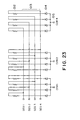
- the element substrate of Figure 23 has electrothermal transducer element 012, wiring 013, diode 014 and contact for external connection.
- electrothermal transducer element 012 wiring 013, diode 014 and contact for external connection.
- the matrix construction constituted by wiring and diode.
- the number of of the contacts 015 for the external connection is reduced to 2n when the number of of the electrothermal transducer elements is n.
- the head having a plurality of of heat generating resistors in 1 nozzle involves the problem of lowering of the ejection efficiency or deviation from a desired ejection amount.
- an ink jet head capable of effecting high image quality recording with high tone gradient and improved ejection efficiency.
- the position of a plurality of heat generating resistors are optimization in a single nozzle (flow path).
- the function elements for driving the heat generating resistors in such a head are built in the same element substrate, by which the number of of the electrical contacts for the external connections can be decreased, and the downsizing of the element substrate is accomplished.
- an ink container for constituting such an ink jet head or ink jet cartridge an ink container to which the ink is refilled is used, so that the repeated use is permitted, so that the ink jet cartridge can be used for a long term.
- an ink jet head comprising a plurality of liquid flow paths for ejecting the ink; and a plurality of heat generating resistors for said respective liquid flow paths, said heat generating resistors being independently drivable; characterised in that adjacent ones of said heat generating resistors are spaced by not more than 8 microns.
- an ink jet head cartridge having a maintaining for containing the ink to above-described ink jet head or the ink jet head.
- an ink jet device having the ink jet head and transporting means for transporting a recording material.
- an ink jet device having a driving signal supply means for driving such an ink jet head or said ink jet head.
- Figure 1 illustrates a bubble generation region of an electrothermal transducer element.
- Figure 2 illustrates a bubble generation region of an electrothermal transducer element.
- Figure 3 illustrates a structure wherein a plurality of of electrothermal transducer are provided in 1 flow path.
- Figure 4 illustrates a bubble generation region of the electrothermal transducer element in Figure 3.
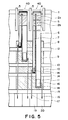
- Figure 5 illustrates an element position on a substrate constituting a base of an ink jet recording head according to an embodiment of the invention.
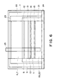
- Figure 6 shows a general arrangement of a substrate constituting a base of the ink jet recording head of Figure 5.
- Figure 7 shows an equivalent circuit of Figure 5.
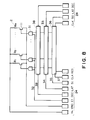
- Figure 8 shows an equivalent circuit of Figure 6.
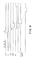
- Figure 9 is timing chart of driving of an ink jet recording head according to and embodiment of the present invention.
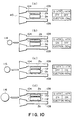
- Figure 10 shows an example of control for ejection state of the ink in an ink jet recording head according to an embodiment of the present invention.
- Figure 11 shows a reflection temperature when an image is formed using a control of Figure 10.
- Figure 12 shows an example of a construction of an ink jet recording head according to an embodiment of the present invention.
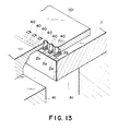
- Figure 13 shows example of a construction of ink jet recording head according to an embodiment of the present invention.
- Figure 14 shows a modified example of Figure 5.
- Figure 15 illustrates an ink jet head cartridge using the head according to an embodiment of the present invention.
- Figure 16 shows an example of a construction of ink jet recording head mounted on an ink jet recording head according to an embodiment of the present invention.
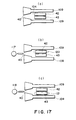
- Figure 17 shows an example of a construction of an ink jet recording head according to another embodiment of the present invention.
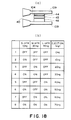
- Figure 18 shows an example of a control for a 8 tone gradient in an ink jet recording head according to an embodiment of the present invention.
- Figure 19 shows example of a construction for analog tone gradient in an ink jet recording head according to an embodiment of the present invention.
- Figure 20 shows example of control for construction of Figure 19.
- Figure 21 shows example of reflection temperature in the construction of Figure 19.
- Figure 22 shows an equivalent circuit for a construction of a substrate of a conventional ink jet head.
- Figure 23 shows an equivalent circuit of a substrate construction of an ink jet head.
- ink is used as the liquid to be ejected, but the present invention is not limited to the ink and is usable with the liquid which can be ejected using the device of the present invention.
- Figure 1 is a top plan view (a) of an electrothermal transducer element on an element substrate, and a A-A sectional view (b) thereof.
- the electrothermal transducer element on the element substrate comprises a heat generating resistor (ejection heater) 2 for producing the heat and electrodes 3A and 3B connected to the ejection heater 2 through a thin film forming process.
- ejection heater heat generating resistor
- the heat produced by the ejection heater 2 heat radiates in a direction of arrow 107 in (a) namely along the surface, and in a direction thereacross as shown in same figure (b).
- the ejection heater 2 has a sandwich structure comprising a heat accumulation layer 105 of low thermal conductivity, a protection layer 103 for protection of the heater and an anti-cavitation layer 104 against shock wave upon collapse of bubble in ink.
- the base 106 is of silicon crystal or the like.
- the thickness of the respective layers is determined so as to transfer the heat from the ejection heater 2 to the ink 108.
- anti-cavitation layer 104 is 0.1-1.0 micron
- protection layer 103 is 0.3-2.0 microns
- heat accumulation layer 105 is 0.5- 5.0 microns approx.
- the base 106 is 0.5-1.0mm, in thickness, usually.
- the bubble generation starts, and is set as a temperature at which the bubble generation occurs stably at the temperature of not less than 300 o C.
- the ejection heater 2 exhibit low durability abruptly when the surface exceeds the temperature of approx. 700-800 o C due to the stress resulting from inserting in thermal-expansion coefficients between the protection layer 103 or between the heat accumulation layer 105 or due to the durable temperature. It is desirable that the surface temperature is controlled so as not to exceed the temperature.
- the ordinate represents a temperature
- the abscissa represents a distance of the ejection heater in the direction of the flow path cross-section.
- a-a' corresponds to the width of the heater in Figure 1
- the temperature distribution at the surface of the anti-cavitation layer 104 is indicated by Temp A.
- the ⁇ T 1 is a bubble generation start temperature and is approx. 300°C
- ⁇ T 2 is a temperature at which the durability changes abruptly. It is different if the thin film material is different but is usually approx. 700-800°C.
- the range of ⁇ T 1 - ⁇ T 2 temperature region is the region where the bubble generation occurs in the ink, as indicated by b-b'
- the temperature distribution at the central portion is flat, and the bubble generation/collapse are stably repeated, and therefore, the more stable printing property can be provided if this region is larger.
- Adjacent the end portion of the heater the heat radiation occurs in the direction of the surface, as shown in Figure 1 with the result that the temperature gradually decreases, and W A is a non-bubble-generation region incapable of bubble generation of the ink although it is on the ejection heater.
- a further outside portion of the ejection heater exhibit some degree of temperature rise due to the heat radiation in the direction of the surface.
- the temperature distribution has an exponentially expanding nature (curve), and therefore, around the ejection heater, a width (approx. 8 microns)of non-bubble-generation exists (non-bubble-generation region).
- a width approximately 8 microns
- non-bubble-generation region In order to improve the ejection efficiency of the ink by reducing this region, it would be considered to rise the overall temperature.
- the temperature of the maximum temperature region at the center portion of the ejection heater would exceed the durability deterioration temperature, that is ⁇ T 2 with the result of reduced lifetime of the ejection heater. For this reason, it is difficult to increase the overall temperature.
- one liquid flow path (nozzle) 31 has a plurality of of ejection heater s(heat generating resistor s) which are independently drivable.
- ejection heaters of rectangular forms which are substantially the same having long sides along the liquid flow path.
- the two ejection heaters are disposed substantially in parallel with each other. They are remote from the ejection outlet substantially at the same distances.
- a temperature distribution as shown in Figure 4 can be provided by optimizing the positions of the plurality of heat generating resistors, so that the non-bubble-generation region can be reduced while maintaining the temperature of the heater in the stabilization region at ⁇ T 1 - ⁇ T 2 .
- Figure 4 shows a temperature distribution on B-B line between the two heaters in Figure 3.
- the temperatures are as indicated by Temp a, Temp a', and therefore, the respective temperatures are the same as conventional ones.
- the portions of the temperature distribution exponentially expanding at the heater edges are overlapped so that the total temperature distribution is as indicated by Temp B, and the effective bubble generation region of the heater is larger as indicated by B than the conventional one as indicated by A.
- the non-bubble-generation region is normally a-b which is approx.
- the non-bubble-generation region is decreased by decreasing the clearance between heater s(heat generating resistor s) to not more than 8 microns so that effective bubble generation area can be enlargement. If d ⁇ 6 microns is satisfied, the temperature rise due to the heat radiation from the 8 microns width of the non-bubble-generation regions become not less than twice, and the minimum temperature point in the temperature distribution Temp b exceeds the level ⁇ T 1 with the result that the non-bubble-generation region is reduced. Further preferably, if d ⁇ 4 microns is satisfied, the bubble generation region can be assured stably with flatter temperature distribution.
- the heater width is not more than 16 microns (2 W A )
- the bubble generation region does not have a flat surface, and therefore, the effective region hardly exists between the unstable region and the durability deterioration region.
- the stabilized effective bubble generation region can be provided even if the heater has a width not more than 16 microns.
- the clearance between the heat generating resistors is a clearance between adjacent edges of the heat generating resistors.
- the non-bubble-generation region of the heat generating resistor is decreased by optimizing the positions of the heat generating resistors (ejection heaters) in one nozzle.
- a plurality of heat generating resistor are provided in a single nozzle, similarly, and the circuit of the element substrate is so constructed as to efficiently driving the heat generating resistors and to downsize the element substrate.
- Figure 5 shows an arrangement of elements integrally built in the element substrate through a semiconductor manufacturing step, in an ink jet head according to an embodiment of the present invention.
- a nozzle walls 5 are provided, and in a single ejection nozzle between adjacent nozzle wall 5, there are provided a large heat generating resistor (ejection heater) 2a and a small ejection heater 2b under the same conditions as in the foregoing embodiment.
- the respective ejection heaters are connected with a common wiring 1 below a lower insulation heater of the ejection heater through through hole 4 so as to be supplied with a voltage.
- Wiring 6 and 7 are connected between large ejection heater 2a and small ejection heater 2b and switching transistor s11 and 10, respectively through the through hole 16.
- the switching transistors 10 and 11 are also disposed below the lower insulation film of the heater.
- signal wiring 17 and 18 is connected between the transistors 10 and 11 and the shift registers and latching circuits 19 and 20. By doing so, the driving of the heater is limited by ON/OFF of the transistors in accordance with the data taken by the shift register and the latching circuit.
- Ground wirings 12, 13, 14 and 15 are connected to emitters of the switching transistors 8, 9, 10 and 11.
- Figure 5 two nozzles are shown.
- Figure 6 shows the entire arrangement of the element substrate.
- the element substrate 1 is constructed by the continuous arrangement of the cells 25 of single structure.
- the common wiring 23 is connected to contact of 24 by a common longitudinal wiring 22 to permit electric energy supply thereto.
- FIG. 7 shows details of the shift register, the latching circuits 19 and 20.
- the the shift register 36, CLK signal line 37 and serial data line 35 are supplied to convert the serial data to the shift register 36 in accordance with the clock signal.
- the data supplied to the shift register 36 are retained in the latch 33 by the latching signal from the latching signal line 34.
- the enabling signal 32 is connected to a AND gate 31 to supply a timing signal for applying the data from the latch 33 to the transistor 11. Since there are two enabling signals 32, the ejection heaters 2a and 2b can be driven simultaneously or at different timing.
- Figure 8 shows an equivalent circuit of the general arrangement of the substrate 23 wherein the cells of Figure 7 are continuously arranged.
- Figure 10 shows a control of ejection amount of ink using the element substrate.
- the ejection nozzle 104 between the nozzle walls 109 is filled with ink.
- the ejection heaters 2a and 2b are heated to generate a bubble, the ink is ejected by the bubble generation pressure through the orifice 40.
- the small ejection heater 2b is energized, and the small droplet 114 of the ink is ejected.
- the ejection amount at this time is approx. 30ng, for example.
- (c) shows the ejection of a large droplet 115 by a large scale bubble generation 112 by energization of the large ejection heater 2a.
- the ejection amount which is proportional to the area of the heater is approx. 60ng.
- both of the small ejection heater 2b and the large ejection heater 2a are energized.
- the area of the ejection heater is 3 times as large as the small ejection heater (in the case of (b)), and the ejection amount is 90ng (30x3).
- the reflection density is as shown in Figure 11. Since the density is proportional to the ink ejection amount, three levels of the densities can be provided. In other words, 4 tone levels are provided by two heaters which are large and small.
- Figure 12 and 13 show the construction around the nozzle. They are called edge shooter type and side shooter type, respectively.
- the ink in the liquid flow path 104 is heated and a bubble is generated by the ejection heaters 3 and 4 to eject the ink through the ejection outlet 40 which is open in the horizontal direction in the drawing (along the surface having the heater) in the edge shooter type, or upwardly (in the direction normal to the surface having the heater) in the side shooter type.
- the element substrate 1 is bonded to the base plate 41, and the nozzle wall 5 is formed in the top plate 101.
- Figure 14 shows a fundamental construction although the substrate is slightly different for the structure shown in Figure 15.
- an insulation film 51 is provided below the ejection heaters 2a and 2b to provide electric insulation between the aluminum wiring B (wiring 6 and 7) at the heater side and aluminum wiring A (common wiring 1, ground wirings 14 and 15).
- the transistors 10 11 are connected with a silicon layer 53 through latch 33 and AND gate 31.
- the transistor 10, 11, AND gate 31, latch 33 and shift register 36 are formed in the silicon layer 53.
- Figure 15 shows an ink jet head cartridge having an ink jet head and a separable ink container containing the ink to be supplied to the ink jet head.
- the injection of the ink into the ink container of the ink jet head cartridge is carried out as follows.
- an ink supply pipe or the like By connection an ink supply pipe or the like to the ink container, an ink introduction path for the ink filling is constituted, and the ink is supplied into the ink container through the ink introduction path.
- ink supply openings the supply opening or the air vent of the ink jet head side and a hole in the wall of the ink container, are usable.
- FIG 16 is a schematic view of an example of the ink jet recording device having the ink jet recording head described above.
- the ink jet recording device IJRA has a lead screw 2040 rotatable through driving force transmission gears 2020 and 2030 in interrelation with the reversible rotation of a driving motor 2010.
- the carriage HC carrying the the ink jet cartridge IJC having integral ink jet wiring head and ink container is supported on the carriage shaft 2050 and the lead screw 2040, and has a pin (unshown) for engagement with a spiral groove 2041 of the lead screw 2040, and is reciprocation moved in the b direction indicated by an arrow a in accordance with the rotation of the lead screw 2040.
- Designated by 2060 is a sheet confining plate, and urges the paper P to the platen roller 2070 along the carriage movement direction.
- a photo-coupler is constituted by elements 2080 and 2090, it confirms existence of a lever 2100 of the carriage HC in this area to effect rotational direction switching of the motor 2010, that is, the photo-coupler functions as a home position detecting means.
- Designated by 2110 is a cap member for caping the before surface of the recording head, and is supported by supporting member 2120.
- Designated by 2130 is a sucking means for sucking the inside of the cap to effect the sucking recovery of the recording head through the opening of the cap.
- a cleaning blade 2140 for cleaning the end surface of the recording head is mounted on a member 2150 for movement in the to and fro direction, and they are supported on a supporting plate 2160 of the main assembly.
- the blade 2140 is not limited to the structure, but known cleaning blade is usable in this example.
- a lever 2170 is operable to start the sucking of the sucking recovery operation and is movable with the movement of a cam 2180 engaged with the carriage HC, so that the driving force from the driving motor 2010 is selectively transmitted by known transmitting means such as clutch switching means.
- the capping, cleaning and sucking recovery operations are carried out when the carriage HC reaches the home position side region, by the operation of the lead screw 2040 at the respective positions. But, another known timing and operation are usable.
- the above-described constructions are preferable individually or in combination in practicing the present invention.
- Figure 17 shows a fundamental structure of a long lifetime heater usable with the present invention.
- a first heater 42 and a second heater 43 juxtaposed along the length has the same heater size. Therefore, the ejection amounts of the droplets 117 and 118 ejected by energizing the first heater 42 and by energizing the second heater 43, are the same. With this structure, the ejection data are alternately assigned to the two heaters to double the heater lifetime.
- the first heater 42 is first used, and the second heater 43 is after the first heater 42 is actuated for a predetermined number of times or the first heater 42 is broken by electric disconnection or the like.
- Figure 18 shows an example of 8 level tone gradient control.
- (a) in this case, the heater sizes of the small ejection heater 2c, intermediate ejection heater 2b and the large ejection heater 2a juxtaposed, satisfy 1: 2: 4.
- the ejection amount can be controlled with increment of 10ng step from 0-70ng, so that the image quality can be improved.
- the manner of the control is shown in (b).
- Figure 19 shows a construction for analog tone gradient. This embodiment uses the fact that the temperature of the ink in the ink jet recording head is influential to the ejection amount, and the ink temperature is controlled to provide a predetermined ejection amount.
- the ink pre-heating heater 44 is effective for pre-heating of the ink to provide fine change of the ejection amount.
- the ink temperature is raided by the signal A applied to the ink pre-heating heater 44, and then the signal B is applied to the ejection heater 2a or 2b to eject the ink.
- point C designates the temperature at which the bubble generation of the ink occurs, and the temperature of the ink provided by the ink pre-heating heater 44 does not exceed this temperature.
- the digital tone gradient of embodiment 1 can be operated as analog-like tone gradient in effect, as shown in Figure 22.
- the change of the ejection amount due to the change of the head temperature can be suppressed by controlling the ink temperature in the ejection nozzle 104 by the ink pre-heating heater 44 to provide a predetermined ejection amount.
- a pre-pulse is applied prior to the main pulse to effect the pre-heating. If the pre-pulse is large, the bubble generation may occur, and therefore, the ink heating is limited to a degree lower than predetermined.
- the ink pre-heating heater 44 is independent from the ejection heater, and therefore, a large heater having low power per unit area of the heater for heating up to a degree of not producing bubble generation, is usable for pre-heating so that the ejection amount control can be enhanced.
- a plurality of heaters are provided in a single nozzle, and the function element is provided in the substrate, by which the following advantageous effects can be provided.
- the cost increase is hardly required despite the foregoing advantages, and the downsizing is accomplished, in the embodiment wherein the function element is provided in the substrate.
Landscapes
- Particle Formation And Scattering Control In Inkjet Printers (AREA)
- Ink Jet (AREA)
Claims (16)
- Tintenstrahlkopf, welcher aufweist:dadurch gekennzeichnet, daß einander angrenzende Wärmeerzeugungswiderstände (2A, 2B) nicht mehr als 8 µm beabstandet sind.eine Vielzahl von Flüssigkeitsströmungskanälen (31) zum Ausstoßen der Tinte undeine Vielzahl von Wärmeerzeugungswiderständen (2A, 2B; 2a, 2b) für die jeweiligen Flüssigkeitsströmungskanäle, wobei die Wärmeerzeugungswiderstände unabhängig ansteuerbar sind,
- Tintenstrahlkopf gemäß Anspruch 1, wobei der Abstand nicht mehr als 6 µm beträgt.
- Tintenstrahlkopf gemäß Anspruch 1, wobei der Wärmeerzeugungswiderstand einen rechteckigen Aufbau mit einer langen Seite entlang dem Flüssigkeitsströmungskanal (31) aufweist.
- Tintenstrahlkopf gemäß Anspruch 1, wobei zwei solcher Wärmeerzeugungswiderstände (2A, 2B) in einem Flüssigkeitsströmungskanal (31) angeordnet sind.
- Tintenstrahlkopf gemäß Anspruch 1, wobei die Vielzahl von Wärmeerzeugungswiderständen (2A, 2B) entlang der Länge im wesentlichen parallel sind.
- Tintenstrahlkopf gemäß Anspruch 1, wobei die Vielzahl von Wärmeerzeugungswiderständen (2a, 2b) auf einem Elementsubstrat (1) angeordnet ist und das Elementsubstrat ein Schieberegister (36) und eine Halteschaltung (33) zum Ansteuern der Vielzahl von Wärmeerzeugungswiderständen (2a, 2b) aufweist.
- Tintenstrahlkopf gemäß Anspruch 4, wobei die zwei Wärmeerzeugungswiderstände (2a, 2b) unterschiedliche Flächen aufweisen.
- Tintenstrahlkopf gemäß Anspruch 4, wobei die zwei Wärmeerzeugungswiderstände (2a, 2b) im wesentlichen denselben Aufbau aufweisen.
- Tintenstrahlkopf gemäß Anspruch 4, wobei ein Abstand von der Ausstoßöffnung (40) zu den zwei Wärmeerzeugungswiderständen (2a, 2b) im wesentlichen gleich ist.
- Tintenstrahlkopf gemäß Anspruch 1, wobei eine Ausstoßrichtung der Tinte mit der Richtung der Wärmeerzeugungswiderstände (2a, 2b) übereinstimmt.
- Tintenstrahlkopf gemäß Anspruch 1, wobei eine Ausstoßrichtung der Tinte im wesentlichen rechtwinklig zu einer Oberfläche der Wärmeerzeugungswiderstände (2a, 2b) ist.
- Tintenstrahlkopfkassette (IJC) zum Ausführen der Aufzeichnung durch Ausstoßen von Tinte, die einen Tintenstrahlkopf gemäß Anspruch 1 und einen Tintenbehälter zum Vorhalten von Tinte für den Tintenstrahlkopf aufweist.
- Tintenstrahlkopfkassette gemäß Anspruch 12, wobei der Tintenbehälter in bezug auf den Tintenstrahlkopf abnehmbar angeordnet ist.
- Tintenstrahl-Aufzeichnungsapparat (IJRA) zum Ausführen der Aufzeichnung durch Ausstoßen von Tinte, welcher aufweist:einen Tintenstrahlkopf gemäß Anspruch 1 undeine Transporteinrichtung (2070) zum Transportieren eines Aufzeichnungsmaterials, auf welchem die Aufzeichnung ausgeführt wird.
- Tintenstrahl-Aufzeichnungsapparat zum Ausführen der Aufzeichnung durch Ausstoßen von Tinte, welcher aufweist:einen Tintenstrahlkopf gemäß Anspruch 1 undeine Ansteuersignal-Zuführeinrichtung zum Ansteuern des Kopfs.
- Tintenbehälter zur Ausbildung einer Tintenstrahlkopfkassette gemäß Anspruch 12, wobei Tinte in den Tintenbehälter nachgefüllt worden ist.
Priority Applications (1)
| Application Number | Priority Date | Filing Date | Title |
|---|---|---|---|
| EP99108703A EP0934829B1 (de) | 1994-10-20 | 1995-10-20 | Tintenstrahldruckverfahren |
Applications Claiming Priority (3)
| Application Number | Priority Date | Filing Date | Title |
|---|---|---|---|
| JP25563194 | 1994-10-20 | ||
| JP6255631A JPH08118641A (ja) | 1994-10-20 | 1994-10-20 | インクジェットヘッド、インクジェットヘッドカートリッジ、インクジェット装置およびインクが再注入されたインクジェットヘッドカートリッジ用インク容器 |
| JP255631/94 | 1994-10-20 |
Related Child Applications (1)
| Application Number | Title | Priority Date | Filing Date |
|---|---|---|---|
| EP99108703A Division EP0934829B1 (de) | 1994-10-20 | 1995-10-20 | Tintenstrahldruckverfahren |
Publications (3)
| Publication Number | Publication Date |
|---|---|
| EP0707963A2 EP0707963A2 (de) | 1996-04-24 |
| EP0707963A3 EP0707963A3 (de) | 1997-03-12 |
| EP0707963B1 true EP0707963B1 (de) | 2000-01-19 |
Family
ID=17281438
Family Applications (2)
| Application Number | Title | Priority Date | Filing Date |
|---|---|---|---|
| EP95116587A Expired - Lifetime EP0707963B1 (de) | 1994-10-20 | 1995-10-20 | Tintenstrahlkopf, Tintenstrahlkopfkassette und Tintenstrahlapparat |
| EP99108703A Expired - Lifetime EP0934829B1 (de) | 1994-10-20 | 1995-10-20 | Tintenstrahldruckverfahren |
Family Applications After (1)
| Application Number | Title | Priority Date | Filing Date |
|---|---|---|---|
| EP99108703A Expired - Lifetime EP0934829B1 (de) | 1994-10-20 | 1995-10-20 | Tintenstrahldruckverfahren |
Country Status (4)
| Country | Link |
|---|---|
| US (3) | US5731828A (de) |
| EP (2) | EP0707963B1 (de) |
| JP (1) | JPH08118641A (de) |
| DE (2) | DE69514611T2 (de) |
Families Citing this family (103)
| Publication number | Priority date | Publication date | Assignee | Title |
|---|---|---|---|---|
| JPH08118641A (ja) | 1994-10-20 | 1996-05-14 | Canon Inc | インクジェットヘッド、インクジェットヘッドカートリッジ、インクジェット装置およびインクが再注入されたインクジェットヘッドカートリッジ用インク容器 |
| DE69534683T2 (de) * | 1994-12-29 | 2006-07-06 | Canon K.K. | Tintenstrahlkopf mit verschiedenen Heizelementen pro Düse und Tintenstrahldrucker unter Verwendung desselben |
| JPH08332727A (ja) * | 1995-06-06 | 1996-12-17 | Canon Inc | インクジェット記録ヘッド及びインクジェット記録装置 |
| US6154237A (en) * | 1995-12-05 | 2000-11-28 | Canon Kabushiki Kaisha | Liquid ejecting method, liquid ejecting head and liquid ejecting apparatus in which motion of a movable member is controlled |
| US6447088B2 (en) * | 1996-01-16 | 2002-09-10 | Canon Kabushiki Kaisha | Ink-jet head, an ink-jet-head cartridge, an ink-jet apparatus and an ink-jet recording method used in gradation recording |
| JP3559647B2 (ja) * | 1996-04-22 | 2004-09-02 | キヤノン株式会社 | インクジェット記録ヘッド、インクジェットヘッドカートリッジ及びインクジェット記録装置 |
| JPH09286108A (ja) * | 1996-04-22 | 1997-11-04 | Canon Inc | インクジェットプリントヘッドの基体、インクジェットプリントヘッド、およびインクジェットプリント装置 |
| DE69724875T2 (de) * | 1996-06-26 | 2004-07-22 | Canon K.K. | Tintenstrahlaufzeichnungskopf und Tintenstrahlaufzeichnungsapparat |
| JPH1071730A (ja) * | 1996-06-27 | 1998-03-17 | Canon Inc | インクジェット記録方法及びその装置とインクジェット記録ヘッド |
| JP3337912B2 (ja) * | 1996-06-28 | 2002-10-28 | キヤノン株式会社 | インクジェットヘッドの駆動方法及びこれを実行するインクジェット装置 |
| JP3554138B2 (ja) * | 1996-06-28 | 2004-08-18 | キヤノン株式会社 | インクジェット記録方法、インクジェット記録ヘッド及びインクジェット記録装置 |
| DE69733043T2 (de) * | 1996-06-28 | 2006-03-09 | Canon K.K. | Verfahren zum Antreiben eines Aufzeichnungskopfes mit mehreren Heizelementen pro Düse |
| JP3408066B2 (ja) * | 1996-07-09 | 2003-05-19 | キヤノン株式会社 | 液体吐出ヘッド、液体吐出ヘッドを用いたヘッドカートリッジ、液体吐出装置、液体吐出方法およびヘッドキット |
| US6020905A (en) * | 1997-01-24 | 2000-02-01 | Lexmark International, Inc. | Ink jet printhead for drop size modulation |
| JPH10230601A (ja) * | 1997-02-19 | 1998-09-02 | Canon Inc | インクジェット記録装置および方法 |
| JP3372821B2 (ja) * | 1997-04-15 | 2003-02-04 | キヤノン株式会社 | インクジェット装置、該装置用インクジェットヘッドの温度推定方法および制御方法 |
| JP3625357B2 (ja) * | 1997-06-06 | 2005-03-02 | キヤノン株式会社 | 液体輸送方法および液体輸送装置 |
| JP3530717B2 (ja) | 1997-06-19 | 2004-05-24 | キヤノン株式会社 | インクジェット記録方法及び装置 |
| US6030071A (en) * | 1997-07-03 | 2000-02-29 | Lexmark International, Inc. | Printhead having heating element conductors arranged in a matrix |
| JP3639698B2 (ja) * | 1997-07-31 | 2005-04-20 | キヤノン株式会社 | 液体吐出ヘッド、ヘッドカートリッジ、液体吐出記録装置、および液体吐出ヘッドの製造方法 |
| US6375309B1 (en) | 1997-07-31 | 2002-04-23 | Canon Kabushiki Kaisha | Liquid discharge apparatus and method for sequentially driving multiple electrothermal converting members |
| JPH11227209A (ja) | 1997-12-05 | 1999-08-24 | Canon Inc | 液体吐出ヘッド、ヘッドカートリッジおよび液体吐出装置 |
| JPH11227210A (ja) | 1997-12-05 | 1999-08-24 | Canon Inc | 液体吐出ヘッド、該ヘッドの製造方法、ヘッドカートリッジおよび液体吐出装置 |
| US7101099B1 (en) | 1998-08-19 | 2006-09-05 | Canon Kabushiki Kaisha | Printing head, head cartridge having printing head, printing apparatus using printing head, and printing head substrate |
| JP2000127371A (ja) * | 1998-10-27 | 2000-05-09 | Canon Inc | インクジェット記録装置およびインクジェット記録方法 |
| US6471337B1 (en) * | 1998-10-27 | 2002-10-29 | Canon Kabushiki Kaisha | Ink-jet printing apparatus, ejection recovery method for ink-jet printing apparatus, and fabrication method of ink-jet printing head |
| CN1157297C (zh) * | 1999-07-12 | 2004-07-14 | 佳能精技股份有限公司 | 喷墨式图像形成装置 |
| JP2001171126A (ja) * | 1999-10-05 | 2001-06-26 | Canon Inc | 発熱抵抗素子を備えたインクジェットヘッド用基板と、それを用いるインクジェットヘッド、インクジェット装置及び記録方法 |
| JP3787477B2 (ja) * | 2000-02-10 | 2006-06-21 | キヤノン株式会社 | インクジェットヘッドの駆動方法 |
| US6318847B1 (en) * | 2000-03-31 | 2001-11-20 | Hewlett-Packard Company | Segmented heater resistor for producing a variable ink drop volume in an inkjet drop generator |
| KR100413677B1 (ko) * | 2000-07-24 | 2003-12-31 | 삼성전자주식회사 | 버블 젯 방식의 잉크 젯 프린트 헤드 |
| AUPR292301A0 (en) * | 2001-02-06 | 2001-03-01 | Silverbrook Research Pty. Ltd. | A method and apparatus (ART99) |
| JP2003054004A (ja) * | 2001-08-10 | 2003-02-26 | Canon Inc | インクジェット記録装置及びインクジェット記録ヘッド、並びにインクジェット記録方法 |
| US6964469B2 (en) * | 2001-09-28 | 2005-11-15 | Fuji Photo Film Co., Ltd. | Liquid droplet ejection apparatus and ink jet recording head |
| US6601948B1 (en) * | 2002-01-18 | 2003-08-05 | Illinois Tool Works, Inc. | Fluid ejecting device with drop volume modulation capabilities |
| US6712451B2 (en) | 2002-03-05 | 2004-03-30 | Eastman Kodak Company | Printhead assembly with shift register stages facilitating cleaning of printhead nozzles |
| US6871942B2 (en) * | 2002-04-15 | 2005-03-29 | Timothy R. Emery | Bonding structure and method of making |
| JP2004001490A (ja) * | 2002-04-23 | 2004-01-08 | Canon Inc | インクジェットヘッド |
| JP4035385B2 (ja) * | 2002-06-19 | 2008-01-23 | キヤノン株式会社 | 駆動回路、記録ヘッド及び記録装置 |
| JP4266588B2 (ja) * | 2002-07-30 | 2009-05-20 | キヤノン株式会社 | 記録装置及び記録制御方法 |
| JP4161668B2 (ja) | 2002-10-08 | 2008-10-08 | ソニー株式会社 | 液体吐出ヘッド及び液体吐出装置 |
| US6755509B2 (en) * | 2002-11-23 | 2004-06-29 | Silverbrook Research Pty Ltd | Thermal ink jet printhead with suspended beam heater |
| US6896346B2 (en) * | 2002-12-26 | 2005-05-24 | Eastman Kodak Company | Thermo-mechanical actuator drop-on-demand apparatus and method with multiple drop volumes |
| US20040253281A1 (en) * | 2003-06-12 | 2004-12-16 | Atrium Medical Corp. | Therapeutic markings applied to tissue |
| JP4596757B2 (ja) * | 2003-08-05 | 2010-12-15 | キヤノン株式会社 | 記録ヘッド試験装置 |
| US8491076B2 (en) * | 2004-03-15 | 2013-07-23 | Fujifilm Dimatix, Inc. | Fluid droplet ejection devices and methods |
| US7281778B2 (en) | 2004-03-15 | 2007-10-16 | Fujifilm Dimatix, Inc. | High frequency droplet ejection device and method |
| WO2006051762A1 (en) * | 2004-11-10 | 2006-05-18 | Canon Kabushiki Kaisha | Liquid discharge head |
| US8986780B2 (en) | 2004-11-19 | 2015-03-24 | Massachusetts Institute Of Technology | Method and apparatus for depositing LED organic film |
| US8128753B2 (en) | 2004-11-19 | 2012-03-06 | Massachusetts Institute Of Technology | Method and apparatus for depositing LED organic film |
| EP1836056B1 (de) | 2004-12-30 | 2018-11-07 | Fujifilm Dimatix, Inc. | Tintenstrahldruck |
| US7559629B2 (en) * | 2005-09-29 | 2009-07-14 | Lexmark International, Inc. | Methods and apparatuses for implementing multi-via heater chips |
| US7290864B2 (en) | 2005-09-30 | 2007-11-06 | Lexmark International, Inc. | Heater chips with a reduced number of bondpads |
| KR100653088B1 (ko) * | 2005-12-06 | 2006-12-04 | 삼성전자주식회사 | 잉크젯 프린트 헤드의 제조방법 |
| US7484823B2 (en) * | 2005-12-30 | 2009-02-03 | Lexmark International, Inc. | Methods and apparatuses for regulating the temperature of multi-via heater chips |
| US7594708B2 (en) * | 2005-12-30 | 2009-09-29 | Lexmark International, Inc. | Methods and apparatuses for sensing temperature of multi-via heater chips |
| US20080084447A1 (en) * | 2006-10-10 | 2008-04-10 | Silverbrook Research Pty Ltd | Inkjet printhead with adjustable bubble impulse |
| JP4926691B2 (ja) * | 2006-12-21 | 2012-05-09 | キヤノン株式会社 | インクジェット記録ヘッド、およびインクジェット記録ヘッドの製造方法 |
| US7988247B2 (en) | 2007-01-11 | 2011-08-02 | Fujifilm Dimatix, Inc. | Ejection of drops having variable drop size from an ink jet printer |
| TWI322085B (en) * | 2007-03-07 | 2010-03-21 | Nat Univ Tsing Hua | Micro-droplet injector apparatus having nozzle arrays without individual chambers and ejection method of droplets thereof |
| JP4953884B2 (ja) * | 2007-03-30 | 2012-06-13 | キヤノン株式会社 | 記録ヘッド |
| US8556389B2 (en) | 2011-02-04 | 2013-10-15 | Kateeva, Inc. | Low-profile MEMS thermal printhead die having backside electrical connections |
| CN101754859B (zh) * | 2007-06-14 | 2012-05-30 | 麻省理工学院 | 用于沉积膜的方法和设备 |
| JP5197178B2 (ja) * | 2007-06-27 | 2013-05-15 | キヤノン株式会社 | インクジェット記録ヘッド用基板およびインクジェット記録ヘッド |
| US8613814B2 (en) | 2008-03-21 | 2013-12-24 | California Institute Of Technology | Forming of metallic glass by rapid capacitor discharge forging |
| US8613816B2 (en) | 2008-03-21 | 2013-12-24 | California Institute Of Technology | Forming of ferromagnetic metallic glass by rapid capacitor discharge |
| CN101977855B (zh) | 2008-03-21 | 2015-07-29 | 加利福尼亚技术学院 | 通过快速电容器放电形成金属玻璃 |
| US8899171B2 (en) | 2008-06-13 | 2014-12-02 | Kateeva, Inc. | Gas enclosure assembly and system |
| US9048344B2 (en) | 2008-06-13 | 2015-06-02 | Kateeva, Inc. | Gas enclosure assembly and system |
| US8383202B2 (en) | 2008-06-13 | 2013-02-26 | Kateeva, Inc. | Method and apparatus for load-locked printing |
| US9604245B2 (en) | 2008-06-13 | 2017-03-28 | Kateeva, Inc. | Gas enclosure systems and methods utilizing an auxiliary enclosure |
| US11975546B2 (en) | 2008-06-13 | 2024-05-07 | Kateeva, Inc. | Gas enclosure assembly and system |
| US10434804B2 (en) | 2008-06-13 | 2019-10-08 | Kateeva, Inc. | Low particle gas enclosure systems and methods |
| US12064979B2 (en) | 2008-06-13 | 2024-08-20 | Kateeva, Inc. | Low-particle gas enclosure systems and methods |
| US12018857B2 (en) | 2008-06-13 | 2024-06-25 | Kateeva, Inc. | Gas enclosure assembly and system |
| US20100188457A1 (en) * | 2009-01-05 | 2010-07-29 | Madigan Connor F | Method and apparatus for controlling the temperature of an electrically-heated discharge nozzle |
| US9539628B2 (en) | 2009-03-23 | 2017-01-10 | Apple Inc. | Rapid discharge forming process for amorphous metal |
| EP2425470A2 (de) * | 2009-05-01 | 2012-03-07 | Kateeva, Inc. | Verfahren und vorrichtung für organischen dampfstrahldruck |
| US8393702B2 (en) * | 2009-12-10 | 2013-03-12 | Fujifilm Corporation | Separation of drive pulses for fluid ejector |
| US8499598B2 (en) | 2010-04-08 | 2013-08-06 | California Institute Of Technology | Electromagnetic forming of metallic glasses using a capacitive discharge and magnetic field |
| US8864276B2 (en) | 2010-05-10 | 2014-10-21 | Canon Kabushiki Kaisha | Printhead and printing apparatus utilizing data signal transfer error detection |
| JP5393596B2 (ja) | 2010-05-31 | 2014-01-22 | キヤノン株式会社 | インクジェット記録装置 |
| CN103328675B (zh) | 2010-12-23 | 2016-01-06 | 加利福尼亚技术学院 | 通过迅速电容器放电的金属玻璃的片材形成 |
| JP5939545B2 (ja) | 2011-02-16 | 2016-06-22 | カリフォルニア インスティチュート オブ テクノロジー | 急速コンデンサ放電による金属ガラスの射出成形 |
| WO2012138366A1 (en) | 2011-04-08 | 2012-10-11 | Kateeva, Inc. | Method and apparatus for printing using a facetted drum |
| US9315019B2 (en) | 2011-04-29 | 2016-04-19 | Hewlett-Packard Development Company, L.P. | Systems and methods for degassing fluid |
| WO2013162617A1 (en) * | 2012-04-28 | 2013-10-31 | Hewlett-Packard Development Company, L.P. | Dual-mode inkjet nozzle operation |
| US9393612B2 (en) | 2012-11-15 | 2016-07-19 | Glassimetal Technology, Inc. | Automated rapid discharge forming of metallic glasses |
| WO2014145747A1 (en) | 2013-03-15 | 2014-09-18 | Glassimetal Technology, Inc. | Methods for shaping high aspect ratio articles from metallic glass alloys using rapid capacitive discharge and metallic glass feedstock for use in such methods |
| US20140307033A1 (en) * | 2013-04-10 | 2014-10-16 | Yonglin Xie | Pre-heating liquid ejected from a liquid dispenser |
| US10273568B2 (en) | 2013-09-30 | 2019-04-30 | Glassimetal Technology, Inc. | Cellulosic and synthetic polymeric feedstock barrel for use in rapid discharge forming of metallic glasses |
| CN104630661B (zh) | 2013-10-03 | 2017-04-26 | 格拉斯金属技术股份有限公司 | 用于金属玻璃的快速放电形成的涂覆有绝缘膜的进料桶 |
| WO2015100375A1 (en) | 2013-12-26 | 2015-07-02 | Kateeva, Inc. | Thermal treatment of electronic devices |
| WO2015112454A1 (en) | 2014-01-21 | 2015-07-30 | Kateeva, Inc. | Apparatus and techniques for electronic device encapsulation |
| KR102850075B1 (ko) | 2014-04-30 | 2025-08-25 | 카티바, 인크. | 가스 쿠션 장비 및 기판 코팅 기술 |
| US10029304B2 (en) | 2014-06-18 | 2018-07-24 | Glassimetal Technology, Inc. | Rapid discharge heating and forming of metallic glasses using separate heating and forming feedstock chambers |
| JP6448228B2 (ja) * | 2014-06-19 | 2019-01-09 | キヤノン株式会社 | 素子基板および液体吐出ヘッド |
| US10022779B2 (en) | 2014-07-08 | 2018-07-17 | Glassimetal Technology, Inc. | Mechanically tuned rapid discharge forming of metallic glasses |
| US20180290449A1 (en) * | 2015-07-15 | 2018-10-11 | Hewlett-Packard Development Company, L.P. | Adhesion and insulating layer |
| US10682694B2 (en) | 2016-01-14 | 2020-06-16 | Glassimetal Technology, Inc. | Feedback-assisted rapid discharge heating and forming of metallic glasses |
| US10632529B2 (en) | 2016-09-06 | 2020-04-28 | Glassimetal Technology, Inc. | Durable electrodes for rapid discharge heating and forming of metallic glasses |
| JP7397681B2 (ja) * | 2020-01-16 | 2023-12-13 | キヤノン株式会社 | 液体吐出ヘッド |
| JP7713895B2 (ja) * | 2022-02-21 | 2025-07-28 | 理想テクノロジーズ株式会社 | 液体吐出ヘッド |
Family Cites Families (42)
| Publication number | Priority date | Publication date | Assignee | Title |
|---|---|---|---|---|
| CA1127227A (en) | 1977-10-03 | 1982-07-06 | Ichiro Endo | Liquid jet recording process and apparatus therefor |
| DE2945658A1 (de) * | 1978-11-14 | 1980-05-29 | Canon Kk | Fluessigkeitsstrahl-aufzeichnungsverfahren |
| US4317124A (en) | 1979-02-14 | 1982-02-23 | Canon Kabushiki Kaisha | Ink jet recording apparatus |
| AU531269B2 (en) | 1979-03-06 | 1983-08-18 | Canon Kabushiki Kaisha | Ink jet printer |
| JPS55131882A (en) | 1979-04-02 | 1980-10-14 | Canon Inc | Electronic equipment |
| JPS55132259A (en) | 1979-04-02 | 1980-10-14 | Canon Inc | Liquid jet recording method |
| DE2913265A1 (de) * | 1979-04-03 | 1980-10-30 | Wabco Fahrzeugbremsen Gmbh | Kombinierte bremssteuereinrichtung in kraftfahrzeugbremsanlagen |
| JPS5656874A (en) | 1979-10-17 | 1981-05-19 | Canon Inc | Ink jet recording device |
| JPS5842466A (ja) * | 1981-09-08 | 1983-03-11 | Canon Inc | 液体噴射記録法 |
| US4646110A (en) * | 1982-12-29 | 1987-02-24 | Canon Kabushiki Kaisha | Liquid injection recording apparatus |
| EP0124312A3 (de) * | 1983-04-29 | 1985-08-28 | Hewlett-Packard Company | Widerstandsanordnungen für thermische Tintenstrahldrucker |
| JPS6235852A (ja) * | 1985-08-09 | 1987-02-16 | Canon Inc | 記録装置 |
| US4965594A (en) * | 1986-02-28 | 1990-10-23 | Canon Kabushiki Kaisha | Liquid jet recording head with laminated heat resistive layers on a support member |
| JPS62261452A (ja) * | 1986-05-09 | 1987-11-13 | Canon Inc | 多値化記録方式 |
| JPS63160853A (ja) * | 1986-12-25 | 1988-07-04 | Canon Inc | 液体噴射記録ヘツド |
| US4860033A (en) * | 1987-02-04 | 1989-08-22 | Canon Kabushiki Kaisha | Base plate having an oxidation film and an insulating film for ink jet recording head and ink jet recording head using said base plate |
| JP2656481B2 (ja) * | 1987-02-13 | 1997-09-24 | キヤノン株式会社 | インクジエツト記録ヘツド |
| JP2793593B2 (ja) * | 1988-03-16 | 1998-09-03 | 株式会社リコー | 液体噴射記録ヘッド |
| JP2713721B2 (ja) | 1988-03-17 | 1998-02-16 | 株式会社リコー | 液体噴射記録方法 |
| US4994825A (en) * | 1988-06-30 | 1991-02-19 | Canon Kabushiki Kaisha | Ink jet recording head equipped with a discharging opening forming member including a protruding portion and a recessed portion |
| US5081474A (en) * | 1988-07-04 | 1992-01-14 | Canon Kabushiki Kaisha | Recording head having multi-layer matrix wiring |
| US5208604A (en) * | 1988-10-31 | 1993-05-04 | Canon Kabushiki Kaisha | Ink jet head and manufacturing method thereof, and ink jet apparatus with ink jet head |
| ES2076217T3 (es) * | 1988-10-31 | 1995-11-01 | Canon Kk | Aparato para la impresion por chorros de liquido. |
| JPH02239940A (ja) * | 1989-03-14 | 1990-09-21 | Nec Corp | インクジェットヘッド |
| JP2836749B2 (ja) * | 1989-05-09 | 1998-12-14 | 株式会社リコー | 液体噴射記録ヘッド |
| US5189443A (en) | 1989-09-18 | 1993-02-23 | Canon Kabushiki Kaisha | Recording head having stress-minimizing construction |
| CA2025559C (en) * | 1989-09-18 | 1998-09-15 | Masaaki Izumida | Liquid jet recording head and liquid jet recording apparatus having same |
| US4980702A (en) * | 1989-12-28 | 1990-12-25 | Xerox Corporation | Temperature control for an ink jet printhead |
| DE69127707T2 (de) | 1990-01-25 | 1998-01-29 | Canon Kk | Tintenstrahlaufzeichnungskopf, Substrat dafür und Tintenstrahlaufzeichnungsgerät |
| JP2752491B2 (ja) * | 1990-02-02 | 1998-05-18 | キヤノン株式会社 | 液体噴射記録装置 |
| DE69110523T2 (de) * | 1990-04-09 | 1995-11-30 | Seiko Instr Inc | Ansteuerverfahren für ein thermisches Druckelement. |
| ATE137172T1 (de) | 1990-06-15 | 1996-05-15 | Canon Kk | Tintenstrahlaufzeichnungsgerät mit wärme erzeugendem element |
| US5214450A (en) * | 1990-06-15 | 1993-05-25 | Canon Kabushiki Kaisha | Thermal ink jet recording apparatus using a grouped transducer drive |
| ES2100278T3 (es) * | 1991-01-18 | 1997-06-16 | Canon Kk | Unidad para chorros de liquido con orificios y aparato de impresion que utiliza la misma. |
| DE69232385T2 (de) * | 1991-03-20 | 2002-07-11 | Canon K.K., Tokio/Tokyo | Temperatursteuerung für thermischen Tintenstrahlaufzeichnungskopf |
| EP0525787B1 (de) | 1991-08-01 | 1996-10-16 | Canon Kabushiki Kaisha | Aufzeichnungskopfherstellungsverfahren |
| CA2108302C (en) | 1992-10-15 | 2000-12-19 | Yuji Kamiyama | Ink jet recording apparatus |
| DE69402901T2 (de) * | 1993-02-26 | 1997-11-20 | Canon Kk | Tintenstrahldruckkopf, Tintenstrahlkopf-Kartusche und Druckgerät |
| US5640183A (en) | 1994-07-20 | 1997-06-17 | Hewlett-Packard Company | Redundant nozzle dot matrix printheads and method of use |
| US5646660A (en) * | 1994-08-09 | 1997-07-08 | Encad, Inc. | Printer ink cartridge with drive logic integrated circuit |
| JP3715696B2 (ja) | 1994-10-20 | 2005-11-09 | キヤノン株式会社 | 液体吐出ヘッド、ヘッドカートリッジおよび液体吐出装置 |
| JPH08118641A (ja) | 1994-10-20 | 1996-05-14 | Canon Inc | インクジェットヘッド、インクジェットヘッドカートリッジ、インクジェット装置およびインクが再注入されたインクジェットヘッドカートリッジ用インク容器 |
-
1994
- 1994-10-20 JP JP6255631A patent/JPH08118641A/ja active Pending
-
1995
- 1995-10-20 US US08/546,084 patent/US5731828A/en not_active Expired - Lifetime
- 1995-10-20 DE DE69514611T patent/DE69514611T2/de not_active Expired - Lifetime
- 1995-10-20 EP EP95116587A patent/EP0707963B1/de not_active Expired - Lifetime
- 1995-10-20 DE DE69534674T patent/DE69534674T2/de not_active Expired - Fee Related
- 1995-10-20 EP EP99108703A patent/EP0934829B1/de not_active Expired - Lifetime
-
1997
- 1997-10-15 US US08/951,099 patent/US5880762A/en not_active Expired - Fee Related
-
2001
- 2001-06-20 US US09/885,479 patent/US6439690B2/en not_active Expired - Lifetime
Also Published As
| Publication number | Publication date |
|---|---|
| US20010033304A1 (en) | 2001-10-25 |
| DE69534674D1 (de) | 2006-01-12 |
| DE69534674T2 (de) | 2006-07-20 |
| EP0934829A2 (de) | 1999-08-11 |
| DE69514611D1 (de) | 2000-02-24 |
| EP0707963A2 (de) | 1996-04-24 |
| EP0934829A3 (de) | 1999-09-29 |
| JPH08118641A (ja) | 1996-05-14 |
| EP0934829B1 (de) | 2005-12-07 |
| EP0707963A3 (de) | 1997-03-12 |
| DE69514611T2 (de) | 2000-06-29 |
| US5731828A (en) | 1998-03-24 |
| US5880762A (en) | 1999-03-09 |
| US6439690B2 (en) | 2002-08-27 |
Similar Documents
| Publication | Publication Date | Title |
|---|---|---|
| EP0707963B1 (de) | Tintenstrahlkopf, Tintenstrahlkopfkassette und Tintenstrahlapparat | |
| JP3526822B2 (ja) | 高密度の液滴発生器を有するプリントヘッド | |
| US5172134A (en) | Ink jet recording head, driving method for same and ink jet recording apparatus | |
| CA2075097C (en) | Recording apparatus, recording head and substrate therefor | |
| US5754201A (en) | Liquid jet head, head cartridge, liquid jet apparatus, method of ejecting liquid, and method of injecting ink | |
| US5281980A (en) | Ink jet recording head | |
| EP0747221B1 (de) | Tintenstrahlkopf, Tintenstrahlvorrichtung und Tintenstrahlaufzeichnungsverfahren | |
| KR100501855B1 (ko) | 인쇄 헤드 및 화상 인쇄 장치 | |
| EP0627313B1 (de) | Tintenstrahlaufzeichnungskopf und Aufzeichnungsgerät damit versehen | |
| JP2001080074A (ja) | インクジェットプリンタ用プリントヘッド | |
| EP0443801B1 (de) | Aufzeichnungskopf mit Flüssigkeitsausstoss | |
| EP1092544B1 (de) | Tintenstrahldruckvorrichtung und Tintenstrahldruckverfahren | |
| JP4574385B2 (ja) | インクジェット記録ヘッドおよび記録装置 | |
| JP4208399B2 (ja) | インクジェット記録装置、及びインクジェット記録方法 | |
| US8109592B2 (en) | Liquid-ejecting head, liquid-ejecting device, liquid-ejecting method, and ejection medium for liquid-ejecting head | |
| US20030052935A1 (en) | Ink-jet recording apparatus, and ink-temperature control method in the same | |
| JPH0858077A (ja) | インクジェット装置およびインクジェットヘッド | |
| JPH08108538A (ja) | 記録ヘッド及び該記録ヘッドを用いた記録装置 | |
| JPH1016221A (ja) | 液体吐出ヘッドおよび液体吐出装置 | |
| JPH1044411A (ja) | インクジェットプリントヘッドの保温制御装置、インクジェットプリントヘッドおよびインクジェットプリント装置 | |
| JPH06122198A (ja) | インクジェット記録装置 | |
| AU734083B2 (en) | Recording apparatus, recording head and substrate therefor | |
| JP4455013B2 (ja) | 記録ヘッドの駆動方法、記録ヘッド、及び記録装置 | |
| JP2000127405A (ja) | 液体吐出ヘッド、その駆動方法および液体吐出装置 | |
| JP2006224443A (ja) | インクジェット記録ヘッド、記録装置、および記録方法 |
Legal Events
| Date | Code | Title | Description |
|---|---|---|---|
| PUAI | Public reference made under article 153(3) epc to a published international application that has entered the european phase |
Free format text: ORIGINAL CODE: 0009012 |
|
| 17P | Request for examination filed |
Effective date: 19951020 |
|
| AK | Designated contracting states |
Kind code of ref document: A2 Designated state(s): DE FR GB IT |
|
| PUAL | Search report despatched |
Free format text: ORIGINAL CODE: 0009013 |
|
| AK | Designated contracting states |
Kind code of ref document: A3 Designated state(s): DE FR GB IT |
|
| REG | Reference to a national code |
Ref country code: IE Ref legal event code: FG4D Free format text: 78798 |
|
| GRAG | Despatch of communication of intention to grant |
Free format text: ORIGINAL CODE: EPIDOS AGRA |
|
| 17Q | First examination report despatched |
Effective date: 19981102 |
|
| GRAG | Despatch of communication of intention to grant |
Free format text: ORIGINAL CODE: EPIDOS AGRA |
|
| GRAH | Despatch of communication of intention to grant a patent |
Free format text: ORIGINAL CODE: EPIDOS IGRA |
|
| GRAH | Despatch of communication of intention to grant a patent |
Free format text: ORIGINAL CODE: EPIDOS IGRA |
|
| GRAA | (expected) grant |
Free format text: ORIGINAL CODE: 0009210 |
|
| AK | Designated contracting states |
Kind code of ref document: B1 Designated state(s): DE FR GB IT |
|
| REF | Corresponds to: |
Ref document number: 69514611 Country of ref document: DE Date of ref document: 20000224 |
|
| ITF | It: translation for a ep patent filed | ||
| ET | Fr: translation filed | ||
| PLBE | No opposition filed within time limit |
Free format text: ORIGINAL CODE: 0009261 |
|
| STAA | Information on the status of an ep patent application or granted ep patent |
Free format text: STATUS: NO OPPOSITION FILED WITHIN TIME LIMIT |
|
| 26N | No opposition filed | ||
| REG | Reference to a national code |
Ref country code: GB Ref legal event code: IF02 |
|
| PGFP | Annual fee paid to national office [announced via postgrant information from national office to epo] |
Ref country code: IT Payment date: 20081020 Year of fee payment: 14 |
|
| PGFP | Annual fee paid to national office [announced via postgrant information from national office to epo] |
Ref country code: FR Payment date: 20081024 Year of fee payment: 14 |
|
| REG | Reference to a national code |
Ref country code: FR Ref legal event code: ST Effective date: 20100630 |
|
| PG25 | Lapsed in a contracting state [announced via postgrant information from national office to epo] |
Ref country code: FR Free format text: LAPSE BECAUSE OF NON-PAYMENT OF DUE FEES Effective date: 20091102 |
|
| PG25 | Lapsed in a contracting state [announced via postgrant information from national office to epo] |
Ref country code: IT Free format text: LAPSE BECAUSE OF NON-PAYMENT OF DUE FEES Effective date: 20091020 |
|
| PGFP | Annual fee paid to national office [announced via postgrant information from national office to epo] |
Ref country code: DE Payment date: 20131031 Year of fee payment: 19 Ref country code: GB Payment date: 20131018 Year of fee payment: 19 |
|
| REG | Reference to a national code |
Ref country code: DE Ref legal event code: R119 Ref document number: 69514611 Country of ref document: DE |
|
| GBPC | Gb: european patent ceased through non-payment of renewal fee |
Effective date: 20141020 |
|
| PG25 | Lapsed in a contracting state [announced via postgrant information from national office to epo] |
Ref country code: GB Free format text: LAPSE BECAUSE OF NON-PAYMENT OF DUE FEES Effective date: 20141020 Ref country code: DE Free format text: LAPSE BECAUSE OF NON-PAYMENT OF DUE FEES Effective date: 20150501 |