EP0708214A1 - Dispositif de sécurité pour machines à ligaturer les fers à béton - Google Patents
Dispositif de sécurité pour machines à ligaturer les fers à béton Download PDFInfo
- Publication number
- EP0708214A1 EP0708214A1 EP95116364A EP95116364A EP0708214A1 EP 0708214 A1 EP0708214 A1 EP 0708214A1 EP 95116364 A EP95116364 A EP 95116364A EP 95116364 A EP95116364 A EP 95116364A EP 0708214 A1 EP0708214 A1 EP 0708214A1
- Authority
- EP
- European Patent Office
- Prior art keywords
- wire
- reinforcing bars
- guide arm
- binding machine
- loop
- Prior art date
- Legal status (The legal status is an assumption and is not a legal conclusion. Google has not performed a legal analysis and makes no representation as to the accuracy of the status listed.)
- Granted
Links
Images




Classifications
-
- E—FIXED CONSTRUCTIONS
- E04—BUILDING
- E04G—SCAFFOLDING; FORMS; SHUTTERING; BUILDING IMPLEMENTS OR AIDS, OR THEIR USE; HANDLING BUILDING MATERIALS ON THE SITE; REPAIRING, BREAKING-UP OR OTHER WORK ON EXISTING BUILDINGS
- E04G21/00—Preparing, conveying, or working-up building materials or building elements in situ; Other devices or measures for constructional work
- E04G21/12—Mounting of reinforcing inserts; Prestressing
- E04G21/122—Machines for joining reinforcing bars
-
- E—FIXED CONSTRUCTIONS
- E04—BUILDING
- E04G—SCAFFOLDING; FORMS; SHUTTERING; BUILDING IMPLEMENTS OR AIDS, OR THEIR USE; HANDLING BUILDING MATERIALS ON THE SITE; REPAIRING, BREAKING-UP OR OTHER WORK ON EXISTING BUILDINGS
- E04G21/00—Preparing, conveying, or working-up building materials or building elements in situ; Other devices or measures for constructional work
- E04G21/12—Mounting of reinforcing inserts; Prestressing
- E04G21/122—Machines for joining reinforcing bars
- E04G21/123—Wire twisting tools
-
- B—PERFORMING OPERATIONS; TRANSPORTING
- B65—CONVEYING; PACKING; STORING; HANDLING THIN OR FILAMENTARY MATERIAL
- B65B—MACHINES, APPARATUS OR DEVICES FOR, OR METHODS OF, PACKAGING ARTICLES OR MATERIALS; UNPACKING
- B65B13/00—Bundling articles
- B65B13/18—Details of, or auxiliary devices used in, bundling machines or bundling tools
- B65B13/24—Securing ends of binding material
- B65B13/28—Securing ends of binding material by twisting
- B65B13/285—Hand tools
Definitions
- the present invention relates to a reinforcing bars binding machine which plays out a binding wire in a loop manner from a curved guide arm, winds it a plurality of times around the intersecting portions of reinforcing bars and, after then, twists part of the loop-wound portion of the binding wire to thereby tighten the wire and, in particular, to a safety device for use in such reinforcing bars binding machine.
- a main switch is previously turned on, when binding together the reinforcing bars, a trigger is pulled to thereby feed out a wire, the wire is played out in a loop manner from the leading end curved portion of a guide arm and is wound around the intersecting portions of reinforcing bars, and, after then, part of the loop-shaped portion the wire is hitched on a twisting hook and is then twisted and rotated to thereby tighten the wire so as to bind the reinforcing bars to each other efficiently.
- the present invention aims at eliminating the above drawbacks found in the conventional reinforcing bars binding machine. Accordingly, it is an object of the invention to provide a safety device which, for use in a reinforcing bars binding machine, prevents the binding machine from starting even if a trigger is pulled by mistake or carelessly.
- a reinforcing bars binding machine which comprises a wire feed device for feeding out a wire used to bind reinforcing bars to each other, a guide arm for guiding the fed-out wire in such a manner that the wire can be wound around the intersecting portions of the reinforcing bars in a loop manner, a twisting device for holding part of the loop-wound portion of the wire and for twisting and rotating the same to tighten the wire, and a cutting device for cutting the loop-wound portion of the wire from the portion of the wire existing on the wire feed device side, wherein the guide arm is movable in the wire feeding direction, wherein the guide arm is movable in the wire feeding direction, wherein the guide arm is movable in the wire feeding direction, there is provided a safety device which comprises: a spring normally energizing the guide arm in the opposite direction to the wire feeding direction; and detector for detecting that the guide arm is moved in the wire feeding direction against the energization force of the spring, wherein the wire feeding device is operated in
- a safety device for a reinforcing bars binding machine in which a wire fed out from a wire feed device is wound around reinforcing bars in a loop manner, and the wire is held and twisted by a twisting hook to thereby tighten the winding of the wire around the reinforcing bars so as to strongly bind the reinforcing bars together
- the safety device comprising: a contact member engageable with the reinforcing bars when the reinforcing bars are to be bound together, the contact member being movable back and forth; a spring normally energizing the contact member forwardly; and a switch member which, when the contact member is moved backwardly, is engaged with the contact member to thereby allow the binding machine to be operated.
- the safety device described above wherein the contact member comprises two contact elements which are respectively disposed on the right and left sides of the safety device, the switch member comprises two switches which are respectively arranged such that they can be engaged with their respective contact elements, and the binding machine can be operated only when both of the switches are engaged with their respective contact elements.
- the main body of the binding machine is pulled to thereby move the guide arm relatively in the wire feeding direction against the energization force of the spring, before the micro-switch can be turned on.
- the switch of the wire feed device can be put into operation so that the wire wound around a spool can be played out before the guide arm.
- the wire can be wound by the guide arm around the intersecting portions of the reinforcing bars in a loop manner.
- part of the loop-wound portion of the wire is held by the twisting device and is then twisted and rotated by the same device to thereby tighten the wire, and the portion of the wire existing on the wire feed device side is cut off from the binding portion or loop-wound portion of the wire by the cutting device.
- the contact means if the contact means is engaged with the reinforcing bars to thereby press the reinforcing bars binding machine against the reinforcing bars, then the contact means it moved back backwardly against the energization force of the spring, so that the switch means detects the reinforcing bars and thus turns on, thereby enabling the binding machine to be operated. If the binding machine is operated, then the wire fed out from the wire feed device is wound around the reinforcing bars in a loop manner, and part of the loop-wound portion of the wire is held and twisted by the twisting hook to thereby tighten the winding of the wire around the reinforcing bars, so that the reinforcing bars can be bound together strongly.
- the contact means must, be pressed against the reinforcing bars before the binding machine can be operated and, therefore, the unexpected operation of the binding machine can be prevented effectively to thereby secure the safety of the operator.
- the binding machine is prevented from being operated. This prevents the reinforcing bars from being bound together incompletely and thus makes it possible to strongly bind the reinforcing bars together all the times.
- Fig. 1 shows the main portions of a reinforcing bars binding machine which includes a wire feed device 2 for feeding out forwardly a wire 1 which is wound around a spool 7, a guide arm 3 for guiding the fed-out wire 1 to be wound in a loop manner, a twisting device 4 for holding and twisting part of the loop-wound portion of the wound wire 1 to thereby tighten the wire, and a cutting device 5 for cutting off the loop-wound portion of the wire from the base portion of the wire 1.
- the wire feed device 2, twisting device 4 and cutting device 5 are respectively provided in the main body of the binding machine and can be operated with a motor.
- a main switch is previously turned on, and, in binding the reinforcing bars, if a trigger 6 is pulled, then the wire 1 is fed out from the spool 7 by the wire feed device 2 and is then wound in a loop manner by the guide arm 3; and, after then, part of the loop-wound portion of the wire 1 is held by a hook 8 is twisted and rotated to thereby bind together the reinforcing bars, and the loop-wound wire portion is cut off from the base portion of the wire 1 by use of the cutting device 5.
- the leading end portion of the guide arm 3 used to guide and wind the wire 1 in a loop manner is curved in an arc shape, while the base portion 3a of the guide arm is connected to a feed passage 9 for the wire 1 fed by the wire feed device 2.
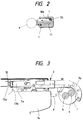
- the curved portion 3b of the guide arm 3 there are formed a first guide groove 10a and a second guide groove 10b which guide the wire 1 in such a manner as shown in Fig. 2, while the first and second guide grooves 10a and 10b are disposed in parallel to each other with a partition wall serving as a guide piece 11 between them and are respectively opened inwardly of the curved portion 3b.
- the cutting device 5 for cutting the wire 1.
- the first guide groove 10a is formed continuously with the feed passage 9 for the wire 1, has a groove width slightly larger than one piece of wire 1, and is used to apply a given kind of curving tendency to the wire 1 when the wire 1 is played out from the curved portion 3b of the guide arm 3. Therefore, the wire 1 that is played out from the curved portion 3b is successively allowed to have a curving tendency of a given curvature so that the wire 1 can circulate around the reinforcing bars in a loop manner.
- the guide arm 3 includes the guide piece 11 by which the leading end of the wire 1 after one circulatory motion thereof can be guided into the second guide groove 10b.
- the guide arm 3 is mounted on the binding machine main body 14 in such a manner that it is free to move in the feeding direction of the wire 1, and also that it is normally energized by a spring 12 in the opposite direction to the wire 1 feeding direction.
- a micro-switch 13 is fixed at a position adjacent to the base end of the guide arm 3 of the binding machine main body 14.
- the micro-switch 13 includes an operative piece 13b which is normally in engagement with the base end of the guide arm and is thus pushed into the switch main body 13a side.
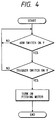
- the micro-switch 13 is disposed in a drive circuit of the binding machine, while the main switch is connected in series to a start switch which can be operated by the trigger 6. Therefore, as shown in Fig. 4.
- the wire feed device 2 can be operated only in accordance with both the detection of the movement of the guide arm 3 by the micro-switch 13 and the turn-on of the start switch by the trigger 6.
- the binding machine main body 14 further includes lock means 15.
- the lock means 15 is normally engaged into an engaging groove 16 formed in the guide arm 3 to lock the guide arm 3 so that the guide arm 3 is prevented from moving in the wire feeding direction, whereas the lock means 15 can be removed from its locking state by the pulling operation of the trigger 6.
- the guide arm 3 can be moved relatively in the wire 1 feeding direction against the energization force of the spring 12. This turns on the micro-switch 13.
- the switch of the wire feed device 2 is put into operation so that the wire 1 wound around the spool 7 is played out before the guide arm 3.
- the leading end of the wire 1, which has been wound as a first circulation in a loop manner around the intersecting portions of the two reinforcing bars a and b by the first guide groove 10a of the guide arm 3, is guided in its second circulation into the second guide groove 10b by the guide piece 11 of the guide arm 3, and, similarly to the first circulation, it is guided in a loop manner. Further, at and from the third and fourth circulations, similarly, the leading end of the wire 1 is guided into the second guide groove 10b by the guide piece 11. And, the portions of the respective circulations of the wire 1 are allowed to move out through an opening formed inside the first and second guide grooves 10a and 10b, and are then wound around the intersecting portions of the reinforcing bars a and b .
- the twisting device 4 is operated at the same time so that the twisting hook 8 holds part of the loop-wound portion of the wire 1 and then twists and rotates the same. Due to this, the loop-wound wire portion fastens strongly the intersecting portions of the two reinforcing bars a and b .
- the wire feed device 2 is operated with the curved portion 3b of the guide arm 3 hitched on the intersecting portions of the reinforcing bars a and b , as shown in Fig. 2, as soon as it comes out of the inside opening of the curved portion 3b, the wire 1 is abutted against the reinforcing bars a and b to thereby eliminate a possibility that any clearance can be produced between the wire 1 and the two reinforcing bars a and b .
- the micro-switch 13 is used to detect that the guide arm 3 is moved to the wire 1 feeding side against the energization force of the spring 12, means for detecting the movement of the guide arm 3 is not limited to the micro-switch 13.
- a light sensor which detects the shielding of the light occurring when the end portion of the guide arm 3 is moved.
- Fig. 5 shows the main portions of a reinforcing bars binding machine according to the second embodiment which includes a wire feed device 23 for feeding out forwardly a wire 22 wound around a spool 21, a guide arm 24 for guiding the fed-out wire 22 such that the wire 22 can be wound around the intersecting portions of reinforcing bars a and b in a loop manner, a twisting device 25 for holding and twisting part of the loop-wound portion of the thus wound wire 22 to thereby tighten the winding of the wire 22 around the reinforcing bars a and b , and a cutting device 26 for cutting off the loop-wound portion of the wire 22 from the base portion of the wire 22.
- the wire feed device 23, twisting device 25 and cutting device 26 are disposed in a binding machine main body 27 and can be operated by a motor (not shown).
- the guide arm 24, which guides the wire 22 around the reinforcing bars includes a leading end which is curved in an arc shape, while the base portion side of the guide arm 24 is connected with a feed passage 30 for the wire 22 that is fed by the wire feed device 23.
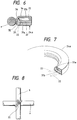
- the curved portion 24a of the guide arm 24 as shown in Figs. 6 and 7, there are formed a first guide groove 31a and a second guide groove 31b for guiding the wire 22, which are arranged in parallel to each other with a partition wall 32 between them and are respectively opened inwardly of the curvature of the curved portion 24a.
- the cutting device 26 which is used to cut off the wire 22.
- the first guide groove 31a is a groove which is formed continuous with the feed passage 30 for the wire 22, and the groove width of the first guide groove 31a is set slightly larger than the diameter of one piece of wire 22 so as to be able to apply a given curving tendency to the wire 22 when it is played out from the curved portion 24a of the guide arm 24. Therefore, the wire 22 that is played out from the cured portion 24a is successively given a curving tendency of a give curvature so that the wire 22 is allowed to run around the reinforcing bars in a loop manner.
- the second guide groove 31b is a groove which is used to guide the loop-winding of the wire 22 after the wire 22 has run once around the reinforcing bars, in particular, the second and its following loop-windings of the wire 22, while the groove width of the second guide groove 31b is formed wider than that of the first guide groove 31a. Also, each of the second and its following loop-windings of the wire 22 becomes slightly larger than the first loop-winding of the wire 22 due to the return of the wire 22 and, for this reason, the diameter of each of the second and its following loop-windings of the wire 22 is larger than the first guide groove 31a.
- the first and second guide grooves 31a and 31b respectively include side walls 33 and 34 which are respectively opposed to the partition wall 32.
- the side walls 33 and 34 are projected inwardly of the curvature of the curved portion 24a, while the projecting portions thereof 35 and 36 are disposed adjacent to each other. That is, the projecting portion 35 of the side wall 33 on the first guide groove 31a side is arranged so as to come near to the second guide groove 31b side, while the projecting portion 36 of the side wall 34 on the second guide groove 31b side is arranged so as to come near to the first guide groove 31a side. Therefore, the whole groove, which is obtained by combining the first guide groove 31a with the second guide groove 31b, is formed such that it is wide in the inner part thereof and is narrow in the frontage thereof.
- V-shaped guide piece 37 which is used to guide the leading end of the wire 22, which has been wound once, into the second guide groove 31b.
- the wire feed device 23 is operated so that the wire 22 wound around the spool 21 is played out before the guide arm 24.
- the leading end of the wire 22, when it is wound for the second time is guided into the second guide groove 31b by the guide piece 37 of the guide arm 24 and is further guided such that it is wound around the reinforcing bars in a loop shape similarly to the first winding. Further, on the third, fourth windings and following windings, the wire 22 is similarly guided into the second guide groove 31b by the guide piece 37.
- the respective windings of the wire 22 are moved through an opening formed inside the projecting portions 35 and 36 of the side walls 33 and 34 of the first and second guide grooves 31a and 31b and are then wound around the intersecting portions of the reinforcing bars a and b . Since the projecting portions 35 and 36 are formed so as to be adjacent to each other, the loop-wound portions of the wire 32 moved out from the first and second guide grooves 31a and 31b are made to come near to each other so that they can be united well as a whole.
- the wire feed device 23 is caused to stop, and the cutting device 26 is operated to cut off the portion of the wire 22 existing within the first guide groove 31a of the guide arm 24.
- the twisting device 25 is operated so that the twisting hook 29 of the twisting device 25 holds and rotates twistingly part of the loop-wound portion of the wire 22.
- the loop-wound portion of the wire 22 around the reinforcing bars a and b tightens the intersecting portions of the reinforcing bars a and b strongly.
- Fig. 9 shows part of the main portions of a reinforcing bars binding machine according to the third embodiment.
- This reinforcing bars binding machine includes a wire feed device 43 for feeding out forwardly a wire 42 wound around a spool 41, a guide part 44 for guiding the fed-out wire 42 such that the wire 42 can be wound around the intersecting portions of reinforcing bars a in a loop manner, a twisting hook 45 for holding, twisting and tightening the wire 42, and a cutting device 46 for cutting off the loop-wound portion of the wire 42 from the base portion of the wire 42.
- a pair of guide arms 49 and 50 which are disposed opposed to each other and are used to hold inside the wire 42 that has been fed out from the guide part 44 and has gone around the reinforcing bars a in a loop manner.
- the guide arms 49 and 50 are respectively connected to the binding machine main body 48 through two parallel links 51 and 52, while the distance between the two guide arms 49 and 50 can be adjusted according to the thicknesses of the reinforcing bars.
- contact elements 53 and 54 which are respectively formed in a curved plate and are movable back and forth.
- the contact elements 53 and 54 are respectively constructed in a three-layer structure, while the respective front ends 53a and 54a thereof are engageable at given positions with the reinforcing bars introduced from between the guide arms 49 and 50.
- the contact elements 53 and 54 respectively include in the rear portions thereof operative pieces 58 and 59 which are formed projectingly. Further, the contact elements 53 and 54 are normally energized forwardly by a spring (not shown).
- one contact element 53 includes in the upper portion of the front end thereof a projecting piece 55 which projects forwardly.
- the front end of the projecting piece 55 is normally projecting more forwardly than the front end of the upper guide arm 49.
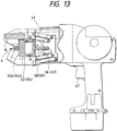
- the binding machine main body 48 On the two sides of the binding machine main body 48, there are provided two switches 56 and 57 which are respectively used to control the operation of the wire feed device 43. As shown in Figs. 10 and 12, in order that the two switches 56 and 57 enable the binding machine including the wire feed device 43, twisting hook 45 and the like to be operated only when both of the contact elements 53 and 54 are moved and engaged with the reinforcing bars, it is preferred that the two switches 56 and 57 are connected in series with the operation circuit of the binding machine.
- the front ends 53a and 54a of the contact elements 53 and 54 are engaged with the reinforcing bars a , as shown in Fig. 13. If the contact elements 53 and 54 are further pressed against the reinforcing bars a , then the contact elements 53 and 54 are moved relatively backwardly against the energization fore of the spring and the operative pieces 58 and 59 of the contact elements 53 and 54 are thereby engaged with the switches 56 and 57 to turn them on. Accordingly, the wire feed device 43 and the like are enabled. Here, if the trigger lever 47 is pulled, then, as shown in Fig.
- the wire feed device 43 is actuated to feed out the wire 42 wound around the spool 41, and the thus fed-out wire 42 is wound two or more times around the intersecting portions of the reinforcing bars a in a loop manner.
- the wire feed device 43 is stopped and the cutting device 46 is operated to cut off the portion of the wire 42 existing within the guide part 44 and, at the same time, the twisting hook 45 (see Fig. 9) is closed, that is, holds and rotates twistingly part of the loop-wound portion of the wire 42. This allows the wire 42 to strongly tighten its winding around the intersecting portions of the reinforcing bars a .
- the loop-wound portion of the wire 42 receives a force which is going to move the loop-wound portion in a direction perpendicular to the diameter direction thereof but, however, because the loop-wound portion of the wire 42 is retained within the upper and lower guide arms, actually, the loop-wound portion of the wire 42 can never be moved laterally.
- two concrete panels may be disposed adjacent to the reinforcing bars respectively on the operation side and on the opposite side with the reinforcing bars between them.
- the contact element 53 may be operated.
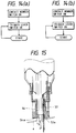
- the binding machine may be structured in such a manner as shown in Fig. 14(a), that is, after the switches 56 and 57 are turned on by pressing the contact elements 53 and 54 against the reinforcing bars a , if the trigger lever 47 is pulled, then the binding operation may be carried out and, after then, if the trigger lever 47 is pulled again, then the binding machine can be operated automatically.
- the binding machine may be structured as shown in Fig. 14(b), that is, if the trigger lever 47 remains pulled, then the binding machine can be operated each time the contact elements 53 and 54 are pressed against the reinforcing bars.
- the guide arm must be put on the intersecting portions of the reinforcing bars but also the trigger must be pulled, before the present reinforcing bars binding machine can be put into operation and, therefore, even if the trigger is pulled by mistake, the binding machine is prevented from starting its operation, which in turn prevents an unexpected accident from happening, that is, the present binding machine is very safe.
- the wire feed device is operated while the curved portion of the guide arm is being hitched on the intersecting portions of the reinforcing bars a and b , as shown in Fig. 2, as soon as it comes out of the inside opening of the curved portion, the wire is abutted against the reinforcing bars a and b to thereby eliminate a possibility that any clearance can be produced between the wire and the reinforcing bars. This prevents the wire from being loosened and thus the tightening of the wire when the wire is twisted by the twisting device can be carried out efficiently, which makes it sure to be able to bind the reinforcing bars to each other.
- the binding machine in a structure in which the switches 56 and 57 to be turned on by pressing the contact elements 53 and 54 against the reinforcing bars are connected in series, as in a case shown in Fig. 15, when the binding machine is obliquely pressed against the reinforcing bars so that only one switch 56 can be turned on, the binding machine cannot be operated. This can prevents the reinforcing bars from being bound but imperfectly.
Landscapes
- Engineering & Computer Science (AREA)
- Architecture (AREA)
- Mechanical Engineering (AREA)
- Civil Engineering (AREA)
- Structural Engineering (AREA)
- Basic Packing Technique (AREA)
Priority Applications (1)
| Application Number | Priority Date | Filing Date | Title |
|---|---|---|---|
| EP99111138A EP0952278B1 (fr) | 1994-10-17 | 1995-10-17 | Machine à ligaturer les fers à béton avec dispositif de sécurité |
Applications Claiming Priority (6)
| Application Number | Priority Date | Filing Date | Title |
|---|---|---|---|
| JP276975/94 | 1994-10-17 | ||
| JP27697594A JP2817636B2 (ja) | 1994-10-17 | 1994-10-17 | 鉄筋結束機における安全機構 |
| JP27697594 | 1994-10-17 | ||
| JP188122/95 | 1995-06-30 | ||
| JP7188122A JP2949703B2 (ja) | 1995-06-30 | 1995-06-30 | 鉄筋結束機における安全装置 |
| JP18812295 | 1995-06-30 |
Related Child Applications (1)
| Application Number | Title | Priority Date | Filing Date |
|---|---|---|---|
| EP99111138A Division EP0952278B1 (fr) | 1994-10-17 | 1995-10-17 | Machine à ligaturer les fers à béton avec dispositif de sécurité |
Publications (2)
| Publication Number | Publication Date |
|---|---|
| EP0708214A1 true EP0708214A1 (fr) | 1996-04-24 |
| EP0708214B1 EP0708214B1 (fr) | 2001-02-28 |
Family
ID=26504742
Family Applications (2)
| Application Number | Title | Priority Date | Filing Date |
|---|---|---|---|
| EP95116364A Expired - Lifetime EP0708214B1 (fr) | 1994-10-17 | 1995-10-17 | Dispositif de sécurité pour machines à ligaturer les fers à béton |
| EP99111138A Expired - Lifetime EP0952278B1 (fr) | 1994-10-17 | 1995-10-17 | Machine à ligaturer les fers à béton avec dispositif de sécurité |
Family Applications After (1)
| Application Number | Title | Priority Date | Filing Date |
|---|---|---|---|
| EP99111138A Expired - Lifetime EP0952278B1 (fr) | 1994-10-17 | 1995-10-17 | Machine à ligaturer les fers à béton avec dispositif de sécurité |
Country Status (3)
| Country | Link |
|---|---|
| US (1) | US5657799A (fr) |
| EP (2) | EP0708214B1 (fr) |
| DE (2) | DE69520188T2 (fr) |
Cited By (4)
| Publication number | Priority date | Publication date | Assignee | Title |
|---|---|---|---|---|
| WO2000036249A1 (fr) * | 1998-11-30 | 2000-06-22 | Lennart Lidman | Procede et dispositif de serrage de barres d'armature |
| WO2010136530A3 (fr) * | 2009-05-27 | 2011-01-27 | Jbj Mechatronic Aps | Appareil de fixation |
| CN104343241A (zh) * | 2013-07-31 | 2015-02-11 | 宁波三泰电子科技有限公司 | 一种全自动钢筋捆扎机的出丝结构 |
| CN113844723A (zh) * | 2021-09-18 | 2021-12-28 | 台州市新大陆电子科技有限公司 | 一种可反馈工作状态的捆扎机及其方法 |
Families Citing this family (13)
| Publication number | Priority date | Publication date | Assignee | Title |
|---|---|---|---|---|
| DE69610371T2 (de) * | 1995-06-30 | 2001-01-25 | Max Co. Ltd., Tokio/Tokyo | Drahtführungsvorrichtung für eine Vorrichtung zum Binden von Armierungseisen und Vorrichtung zum Binden von Armierungseisen |
| JP4396384B2 (ja) * | 2004-05-07 | 2010-01-13 | マックス株式会社 | 鉄筋結束機 |
| JP4548584B2 (ja) * | 2004-07-16 | 2010-09-22 | マックス株式会社 | 鉄筋結束機 |
| WO2009065775A1 (fr) * | 2007-11-20 | 2009-05-28 | Jbj Mechatronic Aps | Appareil de fixation |
| DE102012216831A1 (de) * | 2012-09-19 | 2014-03-20 | Wobben Properties Gmbh | Vorrichtung und Verfahren zum automatischen Verdrillen von Metalldrähten, insbesondere zum Verbinden benachbarter, vorzugsweise sich überkreuzender Strukturelemente |
| JP6887760B2 (ja) | 2016-05-20 | 2021-06-16 | 株式会社マキタ | 鉄筋結束機 |
| DE112017006047T5 (de) | 2017-01-10 | 2019-09-12 | Makita Corporation | Bindewerkzeug |
| JP7175557B2 (ja) | 2018-07-06 | 2022-11-21 | 株式会社共和 | 結束機 |
| WO2020050388A1 (fr) * | 2018-09-07 | 2020-03-12 | マックス株式会社 | Machine de liaison |
| JP7379941B2 (ja) | 2018-09-07 | 2023-11-15 | マックス株式会社 | 結束機 |
| CN114286787A (zh) * | 2019-08-26 | 2022-04-05 | 株式会社牧田 | 钢筋捆扎机 |
| CN111056066A (zh) * | 2019-11-06 | 2020-04-24 | 四川韦克电缆有限公司 | 一种用于捆扎电缆的设备 |
| JP7771550B2 (ja) * | 2021-07-30 | 2025-11-18 | マックス株式会社 | 結束機 |
Citations (6)
| Publication number | Priority date | Publication date | Assignee | Title |
|---|---|---|---|---|
| DE2454905A1 (de) * | 1974-11-20 | 1976-06-16 | Berthold Stempfle | Wickelmaschine zum verflechten von armierungsstaeben bei stahlbetonarbeiten |
| EP0190071A1 (fr) * | 1985-01-17 | 1986-08-06 | Lucien Gaston Bourdain (décédé) | Machine à ligaturer les fers à béton |
| US4685493A (en) * | 1985-02-18 | 1987-08-11 | Sadao Yuguchi | Reinforcing bar binding device |
| EP0249737A2 (fr) * | 1986-05-17 | 1987-12-23 | Kabushiki Kaisha Toyoda Kihan | Appareil pour ligaturer les fers d'armature pour le béton |
| JPH0440686A (ja) | 1990-06-05 | 1992-02-12 | Sony Corp | 磁気テープの巻取り装置 |
| JPH053494U (ja) | 1991-07-03 | 1993-01-19 | マツクス株式会社 | 結束機の針金案内装置 |
-
1995
- 1995-10-17 DE DE69520188T patent/DE69520188T2/de not_active Expired - Fee Related
- 1995-10-17 DE DE69534859T patent/DE69534859T2/de not_active Expired - Fee Related
- 1995-10-17 US US08/573,055 patent/US5657799A/en not_active Expired - Lifetime
- 1995-10-17 EP EP95116364A patent/EP0708214B1/fr not_active Expired - Lifetime
- 1995-10-17 EP EP99111138A patent/EP0952278B1/fr not_active Expired - Lifetime
Patent Citations (6)
| Publication number | Priority date | Publication date | Assignee | Title |
|---|---|---|---|---|
| DE2454905A1 (de) * | 1974-11-20 | 1976-06-16 | Berthold Stempfle | Wickelmaschine zum verflechten von armierungsstaeben bei stahlbetonarbeiten |
| EP0190071A1 (fr) * | 1985-01-17 | 1986-08-06 | Lucien Gaston Bourdain (décédé) | Machine à ligaturer les fers à béton |
| US4685493A (en) * | 1985-02-18 | 1987-08-11 | Sadao Yuguchi | Reinforcing bar binding device |
| EP0249737A2 (fr) * | 1986-05-17 | 1987-12-23 | Kabushiki Kaisha Toyoda Kihan | Appareil pour ligaturer les fers d'armature pour le béton |
| JPH0440686A (ja) | 1990-06-05 | 1992-02-12 | Sony Corp | 磁気テープの巻取り装置 |
| JPH053494U (ja) | 1991-07-03 | 1993-01-19 | マツクス株式会社 | 結束機の針金案内装置 |
Cited By (7)
| Publication number | Priority date | Publication date | Assignee | Title |
|---|---|---|---|---|
| WO2000036249A1 (fr) * | 1998-11-30 | 2000-06-22 | Lennart Lidman | Procede et dispositif de serrage de barres d'armature |
| WO2010136530A3 (fr) * | 2009-05-27 | 2011-01-27 | Jbj Mechatronic Aps | Appareil de fixation |
| CN102459784A (zh) * | 2009-05-27 | 2012-05-16 | Jbj机电一体化有限责任公司 | 捆绑装置 |
| CN102459784B (zh) * | 2009-05-27 | 2014-06-25 | Jbj机电一体化有限责任公司 | 捆绑装置及其使用方法 |
| US9255415B2 (en) | 2009-05-27 | 2016-02-09 | Jbj Mechantronic Aps | Binding apparatus |
| CN104343241A (zh) * | 2013-07-31 | 2015-02-11 | 宁波三泰电子科技有限公司 | 一种全自动钢筋捆扎机的出丝结构 |
| CN113844723A (zh) * | 2021-09-18 | 2021-12-28 | 台州市新大陆电子科技有限公司 | 一种可反馈工作状态的捆扎机及其方法 |
Also Published As
| Publication number | Publication date |
|---|---|
| DE69520188D1 (de) | 2001-04-05 |
| US5657799A (en) | 1997-08-19 |
| DE69534859T2 (de) | 2006-08-24 |
| EP0952278A2 (fr) | 1999-10-27 |
| EP0952278B1 (fr) | 2006-03-08 |
| DE69520188T2 (de) | 2001-06-21 |
| EP0952278A3 (fr) | 2001-04-18 |
| DE69534859D1 (de) | 2006-05-04 |
| EP0708214B1 (fr) | 2001-02-28 |
Similar Documents
| Publication | Publication Date | Title |
|---|---|---|
| US5657799A (en) | Safety device in reinforcing bars binding machine | |
| KR960004050B1 (ko) | 철근 결속기 | |
| JP3604695B2 (ja) | 駆動機構を備えたワイヤ結束具 | |
| EP1418124B1 (fr) | Machine a ligaturer des barres d'acier de renfort | |
| US5909751A (en) | Automatic cable tie installation tool | |
| EP0908582B1 (fr) | Frein pour la bobine de fil d'une machine de ligature de fers d'armatures | |
| TWI864318B (zh) | 捆束機 | |
| US5208948A (en) | Apparatus for and method of binding electric cables | |
| CA2595078A1 (fr) | Outil a lier les barres d'armature | |
| JP3050516B2 (ja) | 結束機におけるワイヤの捨て打ち防止機構 | |
| CN113859616B (zh) | 捆扎机 | |
| JPH056015U (ja) | 結束機の針金リールカバー装置 | |
| JPH08114035A (ja) | 鉄筋結束機における安全機構 | |
| JPH053494U (ja) | 結束機の針金案内装置 | |
| JPH0648411A (ja) | 結束機 | |
| JP2502936Y2 (ja) | 結束機の電源スイッチ制御装置 | |
| JP3487978B2 (ja) | ベルトクランプ結束装置 | |
| JPH053495U (ja) | 結束機の針金送り装置 | |
| JPH0592103U (ja) | 結束機における結束用ワイヤの案内装置 | |
| KR960013081B1 (ko) | 와이어 바인더 | |
| US5471918A (en) | No-load-run strap release control mechanism for a strapping machine | |
| JP2938610B2 (ja) | 緊結装置 | |
| JPH0321788Y2 (fr) | ||
| KR830001031B1 (ko) | 묶음장치(A bundling apparatis) | |
| JPH03615A (ja) | ベルトクランプ自動結束装置のベルト送込み機構 |
Legal Events
| Date | Code | Title | Description |
|---|---|---|---|
| PUAI | Public reference made under article 153(3) epc to a published international application that has entered the european phase |
Free format text: ORIGINAL CODE: 0009012 |
|
| AK | Designated contracting states |
Kind code of ref document: A1 Designated state(s): DE GB SE |
|
| RIN1 | Information on inventor provided before grant (corrected) |
Inventor name: MIYAZAKI,ATSUSHI, C/O MAX CO., LTD. Inventor name: KUSAKARI, ICHIRO, C/O MAX CO., LTD. |
|
| 17P | Request for examination filed |
Effective date: 19960517 |
|
| 17Q | First examination report despatched |
Effective date: 19980616 |
|
| GRAG | Despatch of communication of intention to grant |
Free format text: ORIGINAL CODE: EPIDOS AGRA |
|
| GRAG | Despatch of communication of intention to grant |
Free format text: ORIGINAL CODE: EPIDOS AGRA |
|
| GRAH | Despatch of communication of intention to grant a patent |
Free format text: ORIGINAL CODE: EPIDOS IGRA |
|
| GRAH | Despatch of communication of intention to grant a patent |
Free format text: ORIGINAL CODE: EPIDOS IGRA |
|
| GRAA | (expected) grant |
Free format text: ORIGINAL CODE: 0009210 |
|
| AK | Designated contracting states |
Kind code of ref document: B1 Designated state(s): DE GB SE |
|
| REF | Corresponds to: |
Ref document number: 69520188 Country of ref document: DE Date of ref document: 20010405 |
|
| EN | Fr: translation not filed | ||
| REG | Reference to a national code |
Ref country code: GB Ref legal event code: IF02 |
|
| PLBE | No opposition filed within time limit |
Free format text: ORIGINAL CODE: 0009261 |
|
| STAA | Information on the status of an ep patent application or granted ep patent |
Free format text: STATUS: NO OPPOSITION FILED WITHIN TIME LIMIT |
|
| 26N | No opposition filed | ||
| PGFP | Annual fee paid to national office [announced via postgrant information from national office to epo] |
Ref country code: DE Payment date: 20081014 Year of fee payment: 14 |
|
| PGFP | Annual fee paid to national office [announced via postgrant information from national office to epo] |
Ref country code: SE Payment date: 20081022 Year of fee payment: 14 |
|
| PGFP | Annual fee paid to national office [announced via postgrant information from national office to epo] |
Ref country code: GB Payment date: 20081015 Year of fee payment: 14 |
|
| EUG | Se: european patent has lapsed | ||
| PG25 | Lapsed in a contracting state [announced via postgrant information from national office to epo] |
Ref country code: DE Free format text: LAPSE BECAUSE OF NON-PAYMENT OF DUE FEES Effective date: 20100501 |
|
| PG25 | Lapsed in a contracting state [announced via postgrant information from national office to epo] |
Ref country code: GB Free format text: LAPSE BECAUSE OF NON-PAYMENT OF DUE FEES Effective date: 20091017 |
|
| PG25 | Lapsed in a contracting state [announced via postgrant information from national office to epo] |
Ref country code: SE Free format text: LAPSE BECAUSE OF NON-PAYMENT OF DUE FEES Effective date: 20091018 |