EP0708295A1 - Vorrichtung zur Herstellung von Schutzfilmen in Kesselspeisewasserleitungen - Google Patents
Vorrichtung zur Herstellung von Schutzfilmen in Kesselspeisewasserleitungen Download PDFInfo
- Publication number
- EP0708295A1 EP0708295A1 EP95116574A EP95116574A EP0708295A1 EP 0708295 A1 EP0708295 A1 EP 0708295A1 EP 95116574 A EP95116574 A EP 95116574A EP 95116574 A EP95116574 A EP 95116574A EP 0708295 A1 EP0708295 A1 EP 0708295A1
- Authority
- EP
- European Patent Office
- Prior art keywords
- pipe
- water feed
- feed pipe
- oxygen
- condensate
- Prior art date
- Legal status (The legal status is an assumption and is not a legal conclusion. Google has not performed a legal analysis and makes no representation as to the accuracy of the status listed.)
- Granted
Links
- XLYOFNOQVPJJNP-UHFFFAOYSA-N water Substances O XLYOFNOQVPJJNP-UHFFFAOYSA-N 0.000 title claims abstract description 287
- 230000001681 protective effect Effects 0.000 title claims abstract description 44
- 239000001301 oxygen Substances 0.000 claims abstract description 249
- 229910052760 oxygen Inorganic materials 0.000 claims abstract description 249
- QVGXLLKOCUKJST-UHFFFAOYSA-N atomic oxygen Chemical compound [O] QVGXLLKOCUKJST-UHFFFAOYSA-N 0.000 claims abstract description 248
- UQSXHKLRYXJYBZ-UHFFFAOYSA-N Iron oxide Chemical compound [Fe]=O UQSXHKLRYXJYBZ-UHFFFAOYSA-N 0.000 claims abstract description 46
- MHAJPDPJQMAIIY-UHFFFAOYSA-N Hydrogen peroxide Chemical compound OO MHAJPDPJQMAIIY-UHFFFAOYSA-N 0.000 claims abstract description 10
- CBENFWSGALASAD-UHFFFAOYSA-N Ozone Chemical compound [O-][O+]=O CBENFWSGALASAD-UHFFFAOYSA-N 0.000 claims abstract description 10
- 239000007864 aqueous solution Substances 0.000 claims abstract description 7
- 238000010438 heat treatment Methods 0.000 claims abstract description 4
- 238000000034 method Methods 0.000 claims description 22
- 239000007789 gas Substances 0.000 claims description 14
- 238000001179 sorption measurement Methods 0.000 claims description 6
- 238000007599 discharging Methods 0.000 claims 1
- QGZKDVFQNNGYKY-UHFFFAOYSA-N Ammonia Chemical compound N QGZKDVFQNNGYKY-UHFFFAOYSA-N 0.000 description 81
- 229910021529 ammonia Inorganic materials 0.000 description 33
- 238000001514 detection method Methods 0.000 description 22
- 230000001105 regulatory effect Effects 0.000 description 19
- NLXLAEXVIDQMFP-UHFFFAOYSA-N Ammonium chloride Substances [NH4+].[Cl-] NLXLAEXVIDQMFP-UHFFFAOYSA-N 0.000 description 15
- VHUUQVKOLVNVRT-UHFFFAOYSA-N Ammonium hydroxide Chemical compound [NH4+].[OH-] VHUUQVKOLVNVRT-UHFFFAOYSA-N 0.000 description 15
- 235000011114 ammonium hydroxide Nutrition 0.000 description 15
- 229910021536 Zeolite Inorganic materials 0.000 description 11
- HNPSIPDUKPIQMN-UHFFFAOYSA-N dioxosilane;oxo(oxoalumanyloxy)alumane Chemical compound O=[Si]=O.O=[Al]O[Al]=O HNPSIPDUKPIQMN-UHFFFAOYSA-N 0.000 description 11
- 239000010457 zeolite Substances 0.000 description 11
- 229910000975 Carbon steel Inorganic materials 0.000 description 7
- 230000009471 action Effects 0.000 description 7
- 239000010962 carbon steel Substances 0.000 description 7
- CURLTUGMZLYLDI-UHFFFAOYSA-N Carbon dioxide Chemical compound O=C=O CURLTUGMZLYLDI-UHFFFAOYSA-N 0.000 description 6
- 238000002347 injection Methods 0.000 description 6
- 239000007924 injection Substances 0.000 description 6
- MWUXSHHQAYIFBG-UHFFFAOYSA-N nitrogen oxide Inorganic materials O=[N] MWUXSHHQAYIFBG-UHFFFAOYSA-N 0.000 description 6
- 230000015572 biosynthetic process Effects 0.000 description 5
- 238000011144 upstream manufacturing Methods 0.000 description 5
- IJGRMHOSHXDMSA-UHFFFAOYSA-N Atomic nitrogen Chemical compound N#N IJGRMHOSHXDMSA-UHFFFAOYSA-N 0.000 description 4
- XEEYBQQBJWHFJM-UHFFFAOYSA-N Iron Chemical compound [Fe] XEEYBQQBJWHFJM-UHFFFAOYSA-N 0.000 description 4
- 238000005260 corrosion Methods 0.000 description 4
- 230000007797 corrosion Effects 0.000 description 4
- 230000000694 effects Effects 0.000 description 4
- 239000001569 carbon dioxide Substances 0.000 description 3
- 229910002092 carbon dioxide Inorganic materials 0.000 description 3
- UBAZGMLMVVQSCD-UHFFFAOYSA-N carbon dioxide;molecular oxygen Chemical compound O=O.O=C=O UBAZGMLMVVQSCD-UHFFFAOYSA-N 0.000 description 3
- 230000001276 controlling effect Effects 0.000 description 3
- 239000012535 impurity Substances 0.000 description 3
- UGFAIRIUMAVXCW-UHFFFAOYSA-N Carbon monoxide Chemical compound [O+]#[C-] UGFAIRIUMAVXCW-UHFFFAOYSA-N 0.000 description 2
- RYGMFSIKBFXOCR-UHFFFAOYSA-N Copper Chemical compound [Cu] RYGMFSIKBFXOCR-UHFFFAOYSA-N 0.000 description 2
- MYMOFIZGZYHOMD-UHFFFAOYSA-N Dioxygen Chemical compound O=O MYMOFIZGZYHOMD-UHFFFAOYSA-N 0.000 description 2
- 229910002091 carbon monoxide Inorganic materials 0.000 description 2
- 230000015556 catabolic process Effects 0.000 description 2
- 239000000567 combustion gas Substances 0.000 description 2
- 238000001816 cooling Methods 0.000 description 2
- 229910052802 copper Inorganic materials 0.000 description 2
- 239000010949 copper Substances 0.000 description 2
- 229930195733 hydrocarbon Natural products 0.000 description 2
- 150000002430 hydrocarbons Chemical class 0.000 description 2
- 230000001939 inductive effect Effects 0.000 description 2
- 229910052742 iron Inorganic materials 0.000 description 2
- JEIPFZHSYJVQDO-UHFFFAOYSA-N iron(III) oxide Inorganic materials O=[Fe]O[Fe]=O JEIPFZHSYJVQDO-UHFFFAOYSA-N 0.000 description 2
- 239000000463 material Substances 0.000 description 2
- 229910044991 metal oxide Inorganic materials 0.000 description 2
- 150000004706 metal oxides Chemical class 0.000 description 2
- 239000000203 mixture Substances 0.000 description 2
- 229910052757 nitrogen Inorganic materials 0.000 description 2
- 230000008569 process Effects 0.000 description 2
- 239000000126 substance Substances 0.000 description 2
- 230000002378 acidificating effect Effects 0.000 description 1
- 239000003463 adsorbent Substances 0.000 description 1
- 150000001768 cations Chemical class 0.000 description 1
- 230000006835 compression Effects 0.000 description 1
- 238000007906 compression Methods 0.000 description 1
- 239000000498 cooling water Substances 0.000 description 1
- 239000013078 crystal Substances 0.000 description 1
- 230000001419 dependent effect Effects 0.000 description 1
- 238000010586 diagram Methods 0.000 description 1
- 238000009792 diffusion process Methods 0.000 description 1
- 229910001882 dioxygen Inorganic materials 0.000 description 1
- 230000005686 electrostatic field Effects 0.000 description 1
- 230000005484 gravity Effects 0.000 description 1
- 230000002401 inhibitory effect Effects 0.000 description 1
- 150000002500 ions Chemical class 0.000 description 1
- 239000007788 liquid Substances 0.000 description 1
- 238000012423 maintenance Methods 0.000 description 1
- 230000001590 oxidative effect Effects 0.000 description 1
- 150000002926 oxygen Chemical class 0.000 description 1
- 125000004430 oxygen atom Chemical group O* 0.000 description 1
- 238000005086 pumping Methods 0.000 description 1
- 230000009467 reduction Effects 0.000 description 1
- 230000004044 response Effects 0.000 description 1
- 239000013535 sea water Substances 0.000 description 1
- 239000003643 water by type Substances 0.000 description 1
Images



Classifications
-
- C—CHEMISTRY; METALLURGY
- C23—COATING METALLIC MATERIAL; COATING MATERIAL WITH METALLIC MATERIAL; CHEMICAL SURFACE TREATMENT; DIFFUSION TREATMENT OF METALLIC MATERIAL; COATING BY VACUUM EVAPORATION, BY SPUTTERING, BY ION IMPLANTATION OR BY CHEMICAL VAPOUR DEPOSITION, IN GENERAL; INHIBITING CORROSION OF METALLIC MATERIAL OR INCRUSTATION IN GENERAL
- C23C—COATING METALLIC MATERIAL; COATING MATERIAL WITH METALLIC MATERIAL; SURFACE TREATMENT OF METALLIC MATERIAL BY DIFFUSION INTO THE SURFACE, BY CHEMICAL CONVERSION OR SUBSTITUTION; COATING BY VACUUM EVAPORATION, BY SPUTTERING, BY ION IMPLANTATION OR BY CHEMICAL VAPOUR DEPOSITION, IN GENERAL
- C23C8/00—Solid state diffusion of only non-metal elements into metallic material surfaces; Chemical surface treatment of metallic material by reaction of the surface with a reactive gas, leaving reaction products of surface material in the coating, e.g. conversion coatings, passivation of metals
- C23C8/06—Solid state diffusion of only non-metal elements into metallic material surfaces; Chemical surface treatment of metallic material by reaction of the surface with a reactive gas, leaving reaction products of surface material in the coating, e.g. conversion coatings, passivation of metals using gases
- C23C8/08—Solid state diffusion of only non-metal elements into metallic material surfaces; Chemical surface treatment of metallic material by reaction of the surface with a reactive gas, leaving reaction products of surface material in the coating, e.g. conversion coatings, passivation of metals using gases only one element being applied
- C23C8/10—Oxidising
- C23C8/16—Oxidising using oxygen-containing compounds, e.g. water, carbon dioxide
- C23C8/18—Oxidising of ferrous surfaces
-
- F—MECHANICAL ENGINEERING; LIGHTING; HEATING; WEAPONS; BLASTING
- F22—STEAM GENERATION
- F22B—METHODS OF STEAM GENERATION; STEAM BOILERS
- F22B37/00—Component parts or details of steam boilers
- F22B37/02—Component parts or details of steam boilers applicable to more than one kind or type of steam boiler
- F22B37/04—Component parts or details of steam boilers applicable to more than one kind or type of steam boiler and characterised by material, e.g. use of special steel alloy
-
- F—MECHANICAL ENGINEERING; LIGHTING; HEATING; WEAPONS; BLASTING
- F22—STEAM GENERATION
- F22D—PREHEATING, OR ACCUMULATING PREHEATED, FEED-WATER FOR STEAM GENERATION; FEED-WATER SUPPLY FOR STEAM GENERATION; CONTROLLING WATER LEVEL FOR STEAM GENERATION; AUXILIARY DEVICES FOR PROMOTING WATER CIRCULATION WITHIN STEAM BOILERS
- F22D11/00—Feed-water supply not provided for in other main groups
- F22D11/006—Arrangements of feedwater cleaning with a boiler
-
- Y—GENERAL TAGGING OF NEW TECHNOLOGICAL DEVELOPMENTS; GENERAL TAGGING OF CROSS-SECTIONAL TECHNOLOGIES SPANNING OVER SEVERAL SECTIONS OF THE IPC; TECHNICAL SUBJECTS COVERED BY FORMER USPC CROSS-REFERENCE ART COLLECTIONS [XRACs] AND DIGESTS
- Y10—TECHNICAL SUBJECTS COVERED BY FORMER USPC
- Y10S—TECHNICAL SUBJECTS COVERED BY FORMER USPC CROSS-REFERENCE ART COLLECTIONS [XRACs] AND DIGESTS
- Y10S122/00—Liquid heaters and vaporizers
- Y10S122/07—Feeding air
Definitions
- the present invention relates generally to an apparatus for forming a protective film on the inner surface of a water feed pipe. More particularly, the present invention relates to an apparatus for forming a corrosion-preventing protective film on the inner surface of a water feed pipe, for example, for feeding a condensate from a condenser to a boiler in a steam power plant.
- a steam turbine In a steam power plant, a steam turbine is connected to a power generator, and the generator is driven by the rotation of the steam turbine to generate power.
- a boiler For rotating the steam turbine, a boiler, which heats water into steam is provided. The steam generated in the boiler is blown against the steam turbine to rotate the turbine. The steam blown against the steam turbine is condensed by the condenser, and the resulting condensate is fed back to the boiler.
- a water feed pipe made of carbon steel runs between the condenser and the boiler, and the condensate is fed back to the boiler through this water feed pipe.
- Japanese Unexamined Patent Publication No. Hei 2-157503 discloses a method, in which a very small amount of oxygen is injected from an oxygen bomb into the condensate flowing through the water feed pipe to be dissolved in the condensate.
- An iron oxide (particularly trivalent iron oxide [Fe2O3]) protective film is formed on the inner surface of the water feed pipe by allowing the condensate containing oxygen dissolved therein to flow within the water feed pipe, and thus the water feed pipe is prevented from undergoing corrosion by this protective film.
- the iron oxide protective film is not hardly formed uniformly over the entire inner surface of the water feed pipe.
- the apparatus includes a boiler for receiving water from a water feed pipe and heating the water into steam and a condenser for condensing the steam into condensate.
- the condensate is fed back to the boiler through the water feed pipe.
- a solute including at least one of oxygen, hydrogen peroxide and ozone is supplied to the water feed pipe to form a protective film made of iron oxide on an inner surface of the water feed pipe.
- the apparatus has a solute source.
- Generating member generates an aqueous solution by dissolving the solute supplied from the solute source into water.
- Supplying member supplies the aqueous solution to the water feed pipe to form a protective film made of iron oxide on an inner surface of the water feed pipe.
- FIG. 1 A first embodiment of the present invention will be described below referring to Fig. 1.
- a steam power plant 1 has a boiler 3.
- the boiler 3 has a furnace 4 and an economizer 5 connected to the furnace 4.
- a water pipe (not shown) is distributed in the furnace 4, and the water pipe is heated by combustion gas to convert the water flowing through the water pipe into steam.
- the economizer 5 recovers combustion gas exhausted from the furnace 4 to preheat the water fed to the furnace 4.
- a steam pipe 6 is connected at the proximal end to a steam blowoff port of the furnace 4.
- a separator 7 is located above the steam pipe 6.
- a superheater 8 is located on the steam pipe 6 on the downstream side of the separator 7. The separator 7 separates water drops contained in the steam blown out of the steam blowoff port of the furnace 4 and feeds only the steam to the superheater 8. The superheater 8 heats the steam to a higher temperature.
- the separator 7 is connected to the economizer 5 via a drain pipe 9.
- a drain tank 10 and a circulating pump 11 are located on the drain pipe 9.
- the drain tank 10 recovers the water drops separated from the steam by the separator 7.
- the circulating pump 11 feeds the water drops recovered in the drain tank 10 to the economizer 5 through the drain pipe 9.
- a steam turbine 12 is connected to the downstream end of the steam pipe 6.
- the steam passed through the steam pipe 6 is blown against vanes of the steam turbine 12 to rotate the turbine 12.
- a power generator (not shown) is connected to the steam turbine 12 and is driven by the rotation of the steam turbine 12 to generate power.
- a condenser 13 is connected to the steam turbine 12 and has a plurality of cooling pipes (not shown) through which cooling water such as sea water is passed. The steam passed through the steam turbine 12 is brought into contact with the outer surfaces of the cooling pipes of the condenser 13 and is condensed.
- the condenser 13 is connected to the economizer 5 of the boiler 3 through a carbon steel, water feed pipe 16.
- a condensate pump 17 is located on the water feed pipe 16 at an upstream position to pump the condensate from the condenser 13 to the economizer 5.
- An electromagnetic filter 18 is located on the water feed pipe 16 on the downstream side of the condensate pump 17 to filter off metal oxides such as those of iron and copper contained in the condensate fed from the condensate pump 17.
- a demineralizer 19 is located on the water feed pipe 16 on the downstream side of the electromagnetic filter 18. The demineralizer 19 removes not only salinity dissolved in the condensate but also gases such as oxygen, carbon dioxide and other gaseous components contained in the condensate.
- a booster pump 20, a first heater 21 and a deaerator 22 are located on the water feed pipe 16 on the downstream side of the demineralizer 19.
- the booster pump 20 increases the pressure of the condensate flowing through the water feed pipe 16 and feeds the resulting condensate to the first heater 21.
- the first heater 21 increases the temperature of the condensate before it flows into the deaerator 22.
- the deaerator 22 boils the condensate passed through the first heater 21 to remove gaseous components such as oxygen, carbon dioxide and other gaseous components contained in the condensate.
- the steam generated when the condensate is boiled, in the deaerator 22 is fed back to the condenser 13 through a vent pipe 23 and a return pipe 24.
- a water feed pump 25 and a second heater 26 are located on the water feed pipe 16 on the downstream side of the deaerator 22.
- the water feed pump 25 pumps the condensate passed through the deaerator 22 to the economizer 5 of the boiler 3 through the second heater 26.
- the second heater 26 heats the condensate to a predetermined temperature level before it is pumped to the economizer 5.
- Flow meters 14 and oxygen analyzers 15 are located on the water feed pipe 16 between the demineralizer 19 and the booster pump 20, and between the deaerator 22 and the water feed pump 25, respectively. These flow meters 14 detect the flow rate of the condensate flowing through the water feed pipe 16 to output a detection signal to a control circuit 48. Meanwhile, the oxygen analyzers 15 detect the level of oxygen dissolved in the condensate flowing through the water feed pipe 16 to output a detection signal to the control circuit 48.
- a protective film forming apparatus 2 has an oxygen generator 27.
- the oxygen generator 27 has a compressor (not shown) for compressing air.
- the oxygen generator 27 is for producing a high-purity oxygen according to the PSA (Pressure Swing Adsorption) method.
- PSA Pressure Swing Adsorption
- PSA is a method of producing a high-purity oxygen (80.0 % to 99.5 %) by bringing air into contact with zeolite under high pressure to allow nitrogen, carbon monoxide, carbon dioxide, nitrogen oxides, hydrocarbons, etc., contained in the air to be adsorbed on zeolite.
- Zeolite is an adsorbent having a multiplicity of uniform micropores having a size close to the molecular diameter of the gases on the order of ⁇ (10 ⁇ 8 cm).
- Cations in the crystal structure of zeolite exert electrostatic attractive force against the molecules of the gases to be adsorbed including nitrogen. Accordingly, even if the molecular diameter of oxygen is slightly smaller than those of the gaseous components to be adsorbed, the to-be-adsorbed gaseous components having higher polarity levels are adsorbed on the electrostatic field of zeolite. Thus, oxygen can be separated from these gaseous components adsorbed. Subsequently, pressure is reduced or increased to cause a pressure difference to remove the gaseous components adsorbed on the zeolite. By repeating the above procedures, zeolite can be regenerated so that it can adsorb such gaseous components many times, and thus zeolite can be used indefinitely.
- An oxygen supply pipe 28 has an inlet communicating with the oxygen generator 27 and an outlet communicating with an oxygen dissolving tank 29.
- a diffuser 31 is attached to the outlet of the oxygen supply pipe 28 and is located in the dissolving tank 29.
- a buffer tank 45 and a compressor 30 are located on the oxygen supply pipe 28.
- the buffer tank 45 is for storing a predetermined amount of oxygen generated by the oxygen generator 27.
- the buffer tank 45 has a pressure switch (not shown) which is turned on or off in response to the pressure in the tank 45.
- the oxygen generator 27 is selectively operated and stopped based on the on-off control of the pressure switch such that the inner pressure of the buffer tank 45 is maintained at 1.0 Kgf/cm2.
- the oxygen fed from the buffer tank 45 is compressed by the compressor 30, and the thus compressed oxygen is diffused into the dissolving tank 29 via the diffuser 31.
- the oxygen is dissolved in the condensate poured into the dissolving tank 29.
- the condensate in which oxygen is dissolved shall be hereinafter referred to as oxygen water.
- the temperature of the condensate in the dissolving tank 29 is set to be 30 to 40°C.
- a water pouring pipe 32 has an inlet communicating with the water feed pipe 16 on the downstream side of the booster pump 20 and an outlet connected to the top of the dissolving tank 29.
- a motor operated valve 34, a check valve 33 and a reducing valve 46 are located on the water pouring pipe 32.
- the motor operated valve 34 adjust the flow rate of the condensate fed from the water feed pipe 16 to the dissolving tank 29 through the water pouring pipe 32.
- the aperture of the motor operated valve 34 is controlled by the control circuit 48.
- a relief pipe 35 has an inlet communicating with the top of the dissolving tank 29 and an outlet communicating with the buffer tank 45.
- a check valve 47 and a reducing valve 36 are located on the relief pipe 35.
- a portion of the oxygen that was fed to the dissolving tank 29 that failed to dissolve in the condensate contained in the tank 29 is passed through the relief pipe 35, and after pressure reduction through the reducing valve 36, is released into the buffer tank 45.
- the dissolving tank 29 has a safety valve 37.
- the safety valve 37 is provided for preventing the internal pressure of the dissolving tank 29 from exceeding a predetermined level.
- the valve 37 is designed to open itself automatically whenever the internal pressure of the tank 29 exceeds the predetermined level.
- the dissolving tank 29 has an oxygen analyzer 38 and a level sensor 39.
- the oxygen analyzer 38 detects the level of oxygen dissolved in the condensate contained in the dissolving tank 29 and sends a detection signal to the control circuit 48.
- the level sensor 39 detects the water level of the condensate contained in the dissolving tank 29 and sends a detection signal to the control circuit 48.
- the control circuit 48 controls opening and closing of the motor operated valve 34 based on the detection signal sent from the level sensor 39.
- An oxygen water feed pipe 40 has an inlet connected to the bottom of the dissolving tank 29.
- This supply pipe 40 has a first branch pipe 40a and a second branch pipe 40b.
- the first branch pipe 40a has an outlet communicating with the water feed pipe 16 between the booster pump 20 and the demineralizer 19.
- the second branch pipe 40b has an outlet communicating with the water feed pipe 16 between the deaerator 22 and the water feed pump 25.
- Injection pumps 41, flow meters 42, check valves 43 and motor operated valves 44 are located on the branch pipes 40a,40b, respectively.
- the injection pumps 41 pump the oxygen water contained in the dissolving tank 29 to send it through the branch pipes 40a,40b into the water feed pipe 16.
- the control circuit 48 controls operation of the injection pumps 41 based on the detection signals sent from the oxygen analyzers 15, respectively, so as to maintain the oxygen content of the condensate in the water feed pipe 16 at a predetermined level.
- the temperature of the condensate flowing through the water feed pipe 16 is about 30 to 40°C between the condensate pump 17 and the first heater 21, is about 120°C between the first heater 21 and the deaerator 22, is about 180°C between the deaerator 22 and the second heater 26, and is about 290°C between the second heater 26 and the economizer 5.
- the flow rate of the condensate flowing through the water feed pipe 16 is 800 to 2000 tons/min.
- the oxygen content of the condensate flowing through the water feed pipe 16 is maintained at 150 ppb.
- the injection pressure when the oxygen water is injected to the water feed pipe 16 is 7 to 8 Kg/cm2 at the outlet of the first branch pipe 40a and 9.8 Kg/cm2 at the outlet of the second branch pipe 40b.
- a trivalent iron oxide (Fe2O3) is formed as a protective film on the inner wall surface of the water feed pipe 16 by bringing the oxygen water into contact with the inner wall surface of the water feed pipe 16.
- the thus formed protective film prevents the water feed pipe 16 from undergoing corrosion.
- the trivalent iron oxide has poor solubility in water.
- the steam blown out of the steam blowoff port of the furnace 4 in the boiler 3 passes through the steam pipe 6 and is blown against the steam turbine 12 to rotate the steam turbine 12.
- the steam passed through the steam turbine 12 is cooled by the condenser 13 into a condensate.
- metal oxides such as of iron and copper contained in the condensate are filtered off by the electromagnetic filter 18.
- the demineralizer 19 removes not only the salinity dissolved in the condensate but also oxygen and carbon dioxide gases contained in the condensate.
- the thus treated condensate is fed by the booster pump 20 through the first heater 21 to the deaerator 22, where oxygen, carbon dioxide and other gaseous components dissolved in the condensate are removed.
- the condensate is pumped by the water feed pump 25 through the second heater 26 to the economizer 5 of the boiler 3.
- the steam generated, in the boiler 3 is cooled into a condensate by the condenser 13 after rotating the steam turbine 12, and the condensate is fed back to the boiler 3 through the water feed pipe 16.
- the motor operated valve 34 is opened by the control circuit 48. Then, the condensate flowing through the water feed pipe 16 is partly diverted into the water pouring pipe 32 on the downstream side of the booster pump 20 to be fed into the dissolving tank 29.
- the control circuit 48 estimates that the dissolving tank 29 is filled with the condensate based on the detection signal from the level sensor 39, it closes the motor operated valve 34.
- the oxygen generated in the oxygen generator 27 is force-fed through the oxygen supply pipe 28 by the compressor 30 to be diffused into the condensate in the dissolving tank 29 via the diffuser 31.
- the oxygen is dissolved in the condensate to form oxygen water.
- the internal pressure of the dissolving tank 29 increases as oxygen is released through the diffuser 31.
- the internal pressure of the dissolving tank 29 is designed to be maintained not to exceed a predetermined level by the safety valve 37.
- the portion of oxygen which failed to dissolve in the condensate in the dissolving tank 29 is fed back to the buffer tank 45 through the relief pipe 35.
- the injection, pumps 41 are operated by the control circuit 48, and the oxygen water contained in the dissolving tank 29 is fed through the oxygen water feed pipe 40 into the water feed pipe 16.
- the oxygen water is admixed with the condensate flowing through the water feed pipe 16.
- the amount of the oxygen water to be fed to the water feed pipe 16 is controlled by the control circuit 48 so that the condensate in the water feed pipe 16 may have an oxygen content of 150 ppb.
- a protective film of trivalent iron oxide is formed on the inner wall surface of the cater feed pipe 16 by bringing the condensate admixed with the oxygen water into contact with the inner wall surface of the water feed pipe 16.
- the thus formed protective film prevents the water feed pipe 16 from being corroded by the corrosive materials contained in the condensate. Since, the trivalent ion oxide scarcely dissolves in water even if contacted with the corrosive materials, the protective film formed can be maintained for an extended period.
- oxygen is not directly ejected into the condensate flowing through the water feed pipe 16 but an oxygen water formed beforehand in the dissolving tank 29 is designed to be injected into the condensate flowing through the water feed pipe 16. Since the oxygen water assumes a liquid form, it can be mixed smoothly and homogeneously with the condensate flowing through the water feed pipe 16. In other words, oxygen can be dissolved smoothly and homogeneously in the condensate flowing through the water feed pipe 16. Accordingly, a protective film of iron oxide can be formed uniformly and securely on the inner wall surface of the water feed pipe 16 surely inhibiting corrosion of the water feed pipe 16.
- the positions where the oxygen water is supplied to the water feed pipe 16 are oh the downstream sides of the demineralizer 19 and the deaerator 22, respectively. Accordingly, although oxygen contained in the condensate may be removed by the deaerating actions of these units 19,22, they will not affect the oxygen water supplied to the water feed pipe 16 downstream of there units 19,22.
- the oxygen water is formed by utilizing a portion of the condensate discharged from the condenser 13. Accordingly, there is no need of introducing water from an extra water source for forming the oxygen water.
- the oxygen water and the condensate containing the oxygen water are fed back through the water feed pipe 16 to the boiler 3, where they are converted into steam, and the steam is reconverted into water by the condenser 13 to be red back again through the water feed pipe 16 to the boiler 3. That is, the water employed in the steam power plant 1 can be re-used time and time again without being discharged from the circulating route. Therefore, the running cost of forming the oxygen water is minimized.
- Fig. 2 is a table showing gaseous components contained, in the oxygen in an oxygen bomb (hereinafter referred to as bombs oxygen) in comparison with those contained in the oxygen produced according to the PSA method (hereinafter referred to as PSA oxygen).
- bombs oxygen gaseous components contained, in the oxygen in an oxygen bomb
- PSA oxygen the oxygen produced according to the PSA method
- both the bomb oxygen and the PSA oxygen contain corrosive gases.
- the levels of carbon monoxide, carbon dioxide and nitrogen oxides in the PSA oxygen are about one tenth of that of the bomb oxygen.
- the level of hydrocarbons in the PSA oxygen is about a thirtieth of that of the bomb oxygen.
- the levels of corrosive gases contained in the PSA oxygen are much lower than those of the corrosive gases contained in the bomb oxygen, so that an oxygen water having extremely low corrosive gas contents is formed. Accordingly, the possibility that the internal wall surface of the water feed pipe 16 is corroded by the corrosive gases contained in the oxygen water when it is fed into the condenser flowing through the water feed pipe 16 is much lower. Consequently, an iron oxide protective film can be securely formed on the inner wall surface of the water feed pipe 16.
- Oxygen can be stored in the buffer tank 29 at a very low pressure compared with the oxygen bomb. Accordingly, there is no need for installing a structure for preventing rupture of the tank 29 around it or of providing the space for installing the structure.
- the oxygen generator 27 can continuously produce oxygen according to the PSA method. Accordingly, there are no troublesome procedures for bomb replacement, which facilitates lower cost, maintenance and management of the oxygen generator 27.
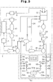
- FIG. 3 A second embodiment of the present invention will be described referring to Fig. 3.
- the constitution of the steam power plant 1 in this embodiment is the same as that of the steam power plant 1 in the first embodiment, so that the similar units and members are called the same and affixed with the same reference numbers, respectively. Accordingly, detailed description of such units and members will be omitted, and differences will mainly be described below.
- a protective film forming apparatus 51 has a bypass pipe 52.
- the bypass pipe 52 has an inlet communicating with the water feed pipe 16 between the demineralizer 19 and the booster pump 20.
- the bypass pipe 52 has a first branch pipe 52a and a second branch pipe 52b.
- the first branch pipe 52a has an outlet communicating with the water feed pipe 16 between the demineralizer 19 and the booster pump 20.
- the second branch pipe 52b has an outlet communicating with the waters feed pipe 16 between the deaerator 22 and the water feed pump 25.
- a motor operated valve 53 and a check valve 54 are located between the inlet of the bypass pipe 52 and the branch point of the branch pipes 52a,52b.
- Flow meters 55, booster pumps 56, ejectors 57, check valves 58 and motor operated valves 59 are located on the branch pipes 52a,52b.
- the flow meters 55 detect flow rate of the condensate flowing through the branch pipes 52a,52b and sends detection signals to a control circuit 67, respectively.
- the control circuit 67 controls the booster pumps 56 based on the detection signals from the flow meters 55 such that the flow rate of the condensate flowing through the branch pipes 52a,52b maybe at a predetermined value (100 L/min).
- the ejectors 57 contain nozzles. The condensate pumped from the booster pumps 56 is jetted from the nozzles at a high speed.
- the motor operated valves 59 are controlled by the control circuit 67.
- An oxygen generator 60 is for producing high-purity oxygen according to the PSA method like in the first embodiment.
- An oxygen supply pipe 61 has an inlet communicating with the oxygen generator 60.
- the oxygen supply pipe 61 has a first branch pipe 61a and a second branch pipe 61b. These branch pipes 61a,61b have outlets communicating with the ejectors 57, respectively.
- Oxygen introducing sections in the ejectors 57 (portions corresponding to the outlets of the branch pipes 61a,61b) assume negative pressure when the condensate is jetted out of the nozzles of the ejectors 57 at a high speed. Accordingly, the oxygen in the branch pipes 61a,61b is sucked into the ejectors 57 and is mixed with the condensate to be jetted out of the nozzles.
- a buffer tank 62 is located on the oxygen supply pipe 61
- the buffer tank 62 has an oxygen analyser 63.
- the oxygen analyzer 63 detects oxygen content in the buffer tank 62 to send a detection signal to the control circuit 67.
- Flow meters 64, flow regulating valves 65 and check valves 66 are located on the branch pipes 61a,61b, respectively.
- the flow meters 64 detect the flow rate of oxygen flowing through the branch pipes 61a,61b to send detection signals to the control circuit 67.
- the control circuit 67 determines the flow rate of oxygen to be supplied to the ejectors 57 based on the detection signal from the oxygen analyzer 63 to control the aperture of the flow regulating valves 65.
- the temperature and flow rate of the condensate flowing through the water feed pipe 16 in this embodiment are the same as in the first embodiment.
- the control circuit 67 controls the flow regulating valves 65 such that the oxygen content in the condensate flowing through the water feed pipe 16 is maintained at 100 ppb.
- the pressure of the condensate flowing through the bypass pipe 52 is 7 to 8 Kg/cm2 between the inlet of the bypass pipe 52 and the respective booster pumps 56.
- the oxygen water is pressurized by the booster pops 56 so that the pressure of the oxygen water from the bypass pipe 52 to the water feed pipe 16 is 9.9 Kg/cm2 or more.
- the oxygen in the buffer tank 62 is sucked into the ejectors 57 through the oxygen supply pipe 61 and is mixed with the condensate to be jetted out of the nozzles.
- the oxygen is dissolved in the condensate, and an oxygen water is formed.
- the oxygen water is supplied from the outlets of the branch pipes 52a,52b of the bypass pipe 52 into the water feed pipe 16.
- the oxygen water is mixed homogeneously with the condensate flowing through the water feed pipe 16 to form a protective film of trivalent iron oxide on the inner wall surface of the water feed pipe 16.
- the control circuit 67 recognizes the oxygen content in the buffer tank 62 based on the detection signal from the oxygen analyzer 63.
- the control circuit 67 determines the flow rate of oxygen to be supplied to the ejectors 57 depending on the detected oxygen content value to control the aperture of the flow regulating valves 65.
- a predetermined concentration of oxygen water is formed, and the oxygen content of the condensate flowing through the water feed pipe 16 can be maintained at 100 ppb by supplying the oxygen water into the water feed pipe 16.
- the oxygen water is formed by admixing in the ejectors 57 oxygen to the condensate jetted out at a high speed. According to this method, oxygen is not used wastefully but is dissolved efficiently in the condensate, so that not only the amount of oxygen to be used but also the cost of forming the oxygen water is reduced.
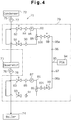
- a steam power plant 71 has a condenser 72, a deaerator 73 and a boiler 74.
- the steam power plant 71 in this embodiment is the same as those in the foregoing embodiments, thus the constitution of the steam power plant 71 depicted in Fig. 4 is simplified.
- a first water feed pipe 75 made of carbon steel connects the condenser 72 and the deaerator 73.
- a second water feed pipe 76 also made of carbon steel, connects the deaerator 73 and the boiler 74.
- a booster pump 77 is located on the first water feed pipe 75 to pump the condensate from the condenser 72 through the first water feed pipe 75 to the deaerator 73.
- a water feed pump 78 is located on the second water feed pipe 76 to pump the condensate from the deaerator 73 through the second water feed pipe 76 to the boiler 74.
- a protective film forming apparatus 79 has a first bypass pipe 80 and a second bypass pipe 81.
- the first bypass pipe 80 has an inlet connected to a position upstreams the first water feed pipe 75 and an outlet also cnnected to the first water feed pipe 75 adjacent to and on the downstream side of the inlet.
- the second bypass pipe 81 has an inlet cnnected to a position upstreams the second water feed pipe 76 and an outlet also connected to the second water feed pipe 76 adjacent to and on the downstream side of the inlet.
- First motor operated valves 82,83, check valves 84,85, pumps 86,87, ejectors 88,89, check valves 90,91 and second motor operated valves 92,93 are located on the bypass pipes 80,81, respectively.
- the first and second motor operated valves 82,83,92,93 open and close the bypasses pipes 80,81, respectively.
- the pumps 86,87 are operated in the state where the bypass pipes 80,81 are opened by the motor operated valves 82,83,92,93, the condensate flowing through the water feed pipes 75,76 partly flows into the bypass pipes 80,81, respectively.
- the condensate flowing through the bypass pipes 80,81 is prevented from flowing backward from the outlet sides to the inlet sides by the check valves 84,85,90,91, respectively.
- An oxygen generator 94 is for producing oxygen according to the PSA method like in the foregoing embodiments.
- An oxygen supply pipe 95 has an inlet communicating with the oxygen generator 94.
- the oxygen supply pipe 95 has a first branch pipe 95a and a second branch pipe 95b. These branch pipes 95a,95b have outlets communicating with the ejectors 88,89, respectively.
- the oxygen in the branch pipes 95a,95b is sucked to the ejectors 88,89 and is mixed with the condensate to be jetted out of the nozzles.
- an oxygen water is formed, and the oxygen water is supplied into the first and second water feed pipes 75,76 from the outlets of the bypass pipes 80,81.
- Flow meters 96,97, flow regulating valves 98,99 and check valves 100,101 are located on the branch pipes 95a,95b, respectively.
- the flow meters 96,97 detect the flow rate of oxygen flowing through the branch pipes 95a,95b, respectively.
- the flow regulating valves 98,99 adjust the flow rate of oxygen flowing through the branch pipes 95a,95b by changing their aperture. The oxygen flowing through the branch pipes 95a,95b is prevented from flowing backward by the check valves 100,101.
- the condensate from the condenser 72 is supplied through the first water feed pipe 75 to the deaerator 73 and further through the second water feed pipe 76 to the boiler 74.
- the condensate flowing through the water feed pipes 75,76 is partly diverted through the inlets of the bypass pipes 80,81 into the pipes 80,81 to flow through them toward the outlets.
- the condensate flowing through the bypass pipes 80,81 is mixed with oxygen fed from the oxygen generator through the oxygen supply pipe 95 when the condensate passes the ejectors 88,89.
- the oxygen water is supplied from the outlets of the bypass pipes 80,81 into the first and second water feed pipes 75,76.
- the oxygen water is mixed homogeneously with the condensate flowing through the first and second water feed pipes 75,76 to form protective films of iron oxide on the inner wall surfaces of the water feed pipes 75,76.
- the bypass pipes 80,81 for feeding the condensate introduced from the water feed pipes 75,76 back into the pipes 75,76 are independently connected to the first water feed pipe 75 between the condenser 72 and the deaerator 73 and to the second water feed pipe 76 between the deaerator 73 and the boiler 74.
- the inlets and outlets of the bypass pipes 80,81 are communicating with the, water feed pipes 75,76 adjacent to each other, respectively. Accordingly, differences in the pressure and temperature of the condensate flowing through the water feed pipes 75,76 are small between the portions where the inlets of the bypass pipes 80,81 are connected and the portions where the outlets of the bypass pipes 80,81 are connected.
- the pumps 86,87 employed in this embodiment may have a smaller pumping force than those employed in the foregoing embodiments. Meanwhile, the difference is small between the temperature of the condensate introduced from the inlets of the bypass pipes 80,81 into the water feed pipes 75,76 and the temperature of the condensate in the water feed pipe 75,76 at the portions where the outlets of the bypass pipes 80,81 are connected.
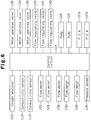
- a fourth embodiment of the present invention will be described referring to Figs. 5 and 6.
- the steam power plant 110 in this embodiment is also the same as those in the foregoing embodiments, thus the constitution of the steam, power plant 110 depicted in Fig. 5 is simplified.
- the steam power plant 110 has a condenser 111, a deaerator 112 and a boiler 113.
- a first water feed pipe 114 made of carbon steel connects the condenser 111 and the deaerator 112.
- a second water feed pipe 115 also made of carbon steel connects the deaerator 112 and the boiler 113.
- a booster pump 116 is located on the first water feed pipe 114 to pump the condensate from the condenser 111 through the first water feed pipe 114 to the deaerator 112.
- a water feed pump 117 is located on the second water feed pipe 115 to pump the condensate from the deaerator 112 through the second water feed pipe 115 to the boiler 113.
- Conductivity sensors 118,119 and a flow meter 120 are located on the first water feed pipe 114.
- the conductivity sensors 118,119 detect pH-dependent conductivity of the condensate flowing through the first water feed pipe 114.
- the flow meter 120 detects the flow rate of the condensate flowing through the first water feed pipe 114.
- Another flow meter 121 and an oxygen analyzer 122 are located on the second water feed pipe 115.
- the flow meter 121 detects the flow rate of the condensate flowing through the second water feed pipe 115.
- the content meter 122 detects the content of oxygen dissolved in the condensate flowing through the second water feed pipe 115.
- a protective film forming apparatus 123 has a control circuit 124 for controlling actions of the entire apparatus 123.
- the control circuit 124 contains a CPU (central processing unit) and ROM (read only memory) storing various programs for operating the CPU.
- the protective film forming apparatus 123 has a bypass pipe 125.
- the bypass pipe 125 has an inlet communicating with the first water feed pipe 114.
- the bypass pipe 125 has a first branch pipe 125a and a second branch pipe 125b.
- the first branch pipe 125a had an outlet communicating with the first water feed pipe 114, whereas the second branch pipe 125b has an outlet communicating with the second water feed pipe 115.
- a motor operated valve 126 and a check valve 127 are interposed between the inlet of the bypass pipe 125 and the branch point of the branch pipes 125a,125b.
- Pumps 128,129, ejectors 130,131, check valves 132,133 and motor operated valves 134,135 are located on the branch pipes 125a,125b, respectively.
- the motor operated valves 126,134,135 open and close the bypass pipe 125, respectively.
- An oxygen supply pipe 136 has at an upstream position a first branch pipe 136a and a second branch pipe 136b and at a downstream position a third branch pipe 136c and a fourth branch pipe 136d.
- the first and second branch pipes 136a,136b have inlets communicating with oxygen generators 137a,137b, respectively. These oxygen generators 137a,137b also produce oxygen according to the PSA method like in the foregoing embodiments.
- the third and fourth branch pipes 136c,136d have outlets communicating with the ejectors 130,131, respectively.
- Flow meters 138,139, flow regulating valves 140,141 and check valves 142,143 are located on the third and fourth branch pipes 136c,136d, respectively.
- the flow meters 138,139 detect the flow rate of oxygen flowing through the branch pipes 136c,136d respectively.
- the flow regulating valves 140,141 adjust the flow rate of oxygen flowing through the branch pipes 136c,136d by changing their apertures.
- a buffer tank 144 is located an the oxygen supply pipe 136 between the branch point of the first and second branch pipes 136a,136b and the branch point of the third and fourth branch pipes 136c,136d.
- the oxygen generated in the oxygen generators 137a,137b passes through the first and second branch pipes 136a,136b and is stored temporarily in the buffer tank 144.
- the buffer tank 144 has a pressure sensor 145 for detecting the internal pressure of the tank 144.
- An ammonia tank 146 stores an aqueous ammonia solution.
- the aqueous ammonia solution has an ammonia content of about 3 %.
- An ammonia supply pipe 147 has an inlet communicating with the ammonia tank 146 and an outlet communicating with the ejector 130.
- a flow meter 148, a flow regulating valve 149 and a check valve 150 are located on the ammonia supply pipe 147.
- the flow meter 148 detects the flow rate of the aqueous ammonia solution flowing through the ammonia supply pipe 147.
- the flow regulating valve 149 adjusts the flow rate of the aqueous ammonia solution flowing through the ammonia supply pipe 147 by changing its aperture.
- the check valve 150 prevents the aqueous ammonia solution flowing through the ammonia supply pipe 147 from flowing backward.
- the condensate flowing through the first branch pipe 125a of the bypass pipe 125 is jetted, when it passes through the ejector 130, at a high speed out of the nozzle of the ejector 130.
- the oxygen in the third branch pipe 136c of the oxygen supply pipe 136 is sucked into the ejector 130 and is mixed with the condensate to be jetted out of the nozzle.
- the aqueous ammonia solution in the ammonia supply pipe 147 is sucked into the ejector 130 and is mixed with the condensate to be jetted out of the nozzle.
- an ammonia-containing oxygen water is formed, and the resulting oxygen water is supplied from the outlet of the first branch. pipe 125a of the bypass pipe 125 into the first water feed pipe 114.
- the oxygen analyzer 122, conductivity sensors 118,119, flow meters 120,121,138,139,148 and pressure sensor 145 are connected to the input end of the control circuit 124.
- the motor operated valves 126,134,135, flow regulating valves 140,141,149, pumps 138,139 and oxygen generators 137a,137b are connected to the output end of the control circuit 124.
- the control circuit 124 actuates the oxygen generator 137a to generate oxygen.
- the oxygen generated in the oxygen generator 137a passes through the first branch pipe 136a and is stored in the buffer tank 144 under compression.
- the pressure sensor 145 detects the internal pressure of the buffer tank 144 to send a detection signal to the control circuit 124.
- the control circuit 124 operates or stops the oxygen generator 137a based on the detection signal from the pressure sensor 145 so as to maintain the internal pressure of the buffer tank 144 within a predetermined range.
- the control circuit 124 stops the oxygen generator 137a.
- the control circuit 124 actuates the oxygen generator 137a. If the oxygen generator 137a becomes inoperable due to a breakdown or the like, the control circuit 124 actuates and controls the other oxygen generator 137b in place of the oxygen generator 137a in the same manner as described above.
- the control circuit 124 allows the motor operated valves 126,134,135 to open the bypass pipes 125, and the pumps 138,139 are operated in this state.
- the oxygen analyzer 122, conductivity censors 118,119 and flow meters 120,121,138,139,148 send detection signals to the control circuit 124, respectively.
- the control circuit 124 recognizes the flow rate of the condensate flowing through the water feed pipes 114,115 based on the detection signals from the flow meters 120,121 to determine the flow rate of the oxygen to be fed to the ejectors 130,131, respectively.
- the control circuit 124 then controls the flow regulating valves 140,141 based on the detection signals from the flow meters 138,139 to adjust the flow rate of oxygen to be supplied to the ejectors 130,131, respectively.
- the control circuit 124 corrects the aperture of the flow regulating valves 140,141 based on the detection signal from the oxygen analyzer 122.
- control circuit 124 controls the aperture of the flow regulating valves 140,141 so that the oxygen content of the condensate flowing through the water feed pipes 114,115 is at a level which allows formation of an iron oxide protective film on the inner wall surfaces of the pipes 114,115 (e.g., 20 to 200 ppb).
- the control circuit 124 recognizes pH value of the condensate flowing through the first water feed pipe 114 based on the detection signal from the conductivity sensor 118 to determine the flow rate of the aqueous ammonia solution to be fed to the ejector 130 depending on the recognized pH value. The control circuit 124 then controls the flow regulating valve 149 based on the detection signal from the flow meter 148 to adjust the flow rate of the aqueous ammonia solution to be supplied to the ejector 130. Further, the control circuit 124 corrects the aperture of the flow regulating valve 149 based on the detection signal from the conductivity sensor 119.
- control circuit 124 controls the aperture of the flow regulating valve 149 such that the pH value of the condensate flowing through the water feed pipes 114,115 is at a level which allows formation of an iron oxide protective film an the inner wall surfaces of the pipes 114,115 (e.g., pH 6.5 to 9).
- the condensate flowing through the first water feed pipe 114 is partly diverted to the bypass pipe 125 to flow through the first and second branch pipes 125a,125b.
- the condensate flowing through the first branch pipe 125a is mixed, when it passes through the ejector 130, with the oxygen supplied from the third branch pipe 136c of the oxygen supply pipe 136 and the aqueous ammonia solution supplied from the ammonia supply pipe 147.
- ammonia-containing oxygen water is formed, and the resulting oxygen water is supplied from the outlet of the first branch pipe 125a into the first water feed pipe 114.
- the ammonia-containing oxygen water is mixed homogeneously with the condensate flowing through the first water feed pipe 114.
- the ammonia fed to the first water feed pipe 114 allows the condensate in the first water feed pipe 114 to assume a pH value which facilitates formation of an iron oxide protective film on the inner wall surface of the pipe 114. Accordingly, an iron oxide protective film is formed efficiently and uniformly on the inner wall surface of the first water feed pipe 114 by the oxygen dissolved in the condensate.
- the condensate flowing though the second branch pipe 125b is mixed, when it passes through the ejector 131, with the oxygen supplied from the fourth branch pipe 136d of the oxygen supply pipe 136.
- an oxygen water is formed, and it is supplied from the outlet of the second branch pipe 125b into the second water feed pipe 115 to be mixed homogeneously with the condensate flowing through the pipe 115.
- the ammonia supplied into the first water feed pipe 114 is contained homogeneously in the condensate flowing through the second water feed pipe 115. Accordingly, an iron oxide protective film is formed efficiently and uniformly on the inner wall surface of the second water feed pipe 115 by the oxygen dissolved in the condensate.
- the internal pressure of the buffer tank 144 is lowered.
- the oxygen generator 137a is actuated, and the oxygen generated in the generator 137a is supplied to the buffer tank 144.
- the oxygen generator 137a is stopped.
- the other oxygen generator 137b is operated in place of the oxygen generator 137a. While it takes about 10 minutes for the oxygen generators 137a,137b after they are actuated and until they can produce oxygen stably, the oxygen remaining in the buffer tank 114 is supplied in the meantime to the branch pipes 125a,125b of the bypass pipe 125 to avoid a lapse.
- the oxygen water and ammonia are not supplied separately into the condensate flowing through the water feed pipe 114, but ammonia is admixed to the oxygen water to form an ammonia-containing oxygen water beforehand, and the ammonia-containing oxygen water is supplied into the water feed pipe 114. Accordingly, the oxygen and ammonia are mixed smoothly and homogeneously with the condensate in the water feed pipe 114 immediately after the ammonia-containing oxygen water is supplied into the water feed pipe 114.
- the ammonia supplied into the first water feed pipe 114 is contained homogeneously in the condensate flowing through the second water feed pipe 115.
- oxygen when the oxygen water is supplied into the second water feed pipe 115, oxygen can be mixed smoothly and homogeneously with the ammonia-containing condensate in the water feed pipe 115, so that iron oxide protective films can be famed efficiently and uniformly on the inner wall surfaces of the water feed pipes 114,115.
- ammonia-containing oxygen water prepared beforehand is designed to be supplied into the water feed pipe 114, oxygen and ammonia can be supplied into the water feed pipe 114 using one pump 128.
- oxygen and an aqueous ammonia solution can be mixed efficiently and homogeneously, with the condensate under the action of the ejector 130. Accordingly, when the ammonia-containing oxygen water is supplied into the water feed pipe 114, the oxygen and ammonia is mixed more securely and homogeneously with the condensate in the water feed pipe 114.
- the oxygen generators 137a,137b are operated and stopped repeatedly such that the internal pressure of the buffer tank 114 is within the range of 0.5 to 1 kgf/cm2, the cost required for running the oxygen generators 137a,137b is minimized.
- the present invention may be modified and embodied, for example, in the following manners:
Landscapes
- Engineering & Computer Science (AREA)
- Chemical & Material Sciences (AREA)
- Mechanical Engineering (AREA)
- Physics & Mathematics (AREA)
- General Engineering & Computer Science (AREA)
- Metallurgy (AREA)
- Thermal Sciences (AREA)
- Materials Engineering (AREA)
- Water Supply & Treatment (AREA)
- Organic Chemistry (AREA)
- Chemical Kinetics & Catalysis (AREA)
- Preventing Corrosion Or Incrustation Of Metals (AREA)
- Physical Water Treatments (AREA)
Applications Claiming Priority (10)
| Application Number | Priority Date | Filing Date | Title |
|---|---|---|---|
| JP257121/94 | 1994-10-21 | ||
| JP25712194 | 1994-10-21 | ||
| JP320660/94 | 1994-12-22 | ||
| JP32066094A JP3619274B2 (ja) | 1994-12-22 | 1994-12-22 | ボイラの給水経路の保護皮膜形成方法 |
| JP326129/94 | 1994-12-27 | ||
| JP32612994A JP2902315B2 (ja) | 1994-10-21 | 1994-12-27 | ボイラの給水処理方法及び同処理装置 |
| JP114787/95 | 1995-05-12 | ||
| JP11478795A JPH08303713A (ja) | 1995-05-12 | 1995-05-12 | ボイラ給水管の腐食防止皮膜形成装置 |
| JP122599/95 | 1995-05-22 | ||
| JP12259995A JP3268716B2 (ja) | 1995-05-22 | 1995-05-22 | ボイラ給水管の腐食防止皮膜形成装置 |
Publications (2)
| Publication Number | Publication Date |
|---|---|
| EP0708295A1 true EP0708295A1 (de) | 1996-04-24 |
| EP0708295B1 EP0708295B1 (de) | 1999-01-07 |
Family
ID=27526662
Family Applications (1)
| Application Number | Title | Priority Date | Filing Date |
|---|---|---|---|
| EP95116574A Expired - Lifetime EP0708295B1 (de) | 1994-10-21 | 1995-10-20 | Vorrichtung zur Herstellung von Schutzfilmen in Kesselspeisewasserleitungen |
Country Status (3)
| Country | Link |
|---|---|
| US (1) | US5797357A (de) |
| EP (1) | EP0708295B1 (de) |
| DE (1) | DE69507106T2 (de) |
Cited By (5)
| Publication number | Priority date | Publication date | Assignee | Title |
|---|---|---|---|---|
| WO2000042294A1 (en) * | 1999-01-13 | 2000-07-20 | Abb Alstom Power Inc. | Material selection and conditioning to avoid brittleness caused by nitriding |
| WO2009138216A3 (de) * | 2008-05-13 | 2010-06-17 | Hitachi Power Europe Gmbh | Chemische wasser-dampf-kreislauf-konditionierung |
| CN102269400A (zh) * | 2011-07-26 | 2011-12-07 | 西安热工研究院有限公司 | 一种电厂锅炉化学清洗中双氧水的加药装置 |
| US8859038B2 (en) | 2010-09-15 | 2014-10-14 | Kabushiki Kaisha Toshiba | Method for monitoring corrosion protection in power plant |
| WO2017055002A1 (de) * | 2015-09-30 | 2017-04-06 | Siemens Aktiengesellschaft | Aktiv-nassdampf-reinigungs-verfahren für dampfturbinen |
Families Citing this family (12)
| Publication number | Priority date | Publication date | Assignee | Title |
|---|---|---|---|---|
| CH691479A5 (de) * | 1996-12-06 | 2001-07-31 | Siemens Ag | Oberflächenbehandlung von Stahl. |
| WO2003076204A1 (en) * | 2002-03-08 | 2003-09-18 | Armor Holdings Forensics, Inc. | Self contained fingerprint ink/inkless reagent applicator and recording substrate |
| US20100095841A1 (en) * | 2008-10-20 | 2010-04-22 | Pacific Consolidated Industries, Inc. | VSA gas concentrator using a reversing blower |
| WO2014078428A1 (en) * | 2012-11-13 | 2014-05-22 | Plexaire Llc | Condensate management system and methods |
| US9383095B2 (en) | 2013-09-18 | 2016-07-05 | Skavis Corporation | Steam generation apparatus and associated control system and methods for providing desired steam quality |
| US9303866B2 (en) | 2013-09-18 | 2016-04-05 | Skavis Corporation | Steam generation apparatus and associated control system and methods for providing a desired injection pressure |
| WO2015041660A1 (en) * | 2013-09-18 | 2015-03-26 | Skavis Corporation | Steam generation apparatus and associated control system and methods |
| US9310070B2 (en) | 2013-09-18 | 2016-04-12 | Skavis Corporation | Steam generation apparatus and associated control system and methods for providing venting |
| US9303865B2 (en) | 2013-09-18 | 2016-04-05 | Skavis Corporation | Steam generation apparatus and associated control system and methods for startup |
| RU2568011C1 (ru) * | 2014-12-09 | 2015-11-10 | Фонд поддержки научной, научно-технической и инновационной деятельности "Энергия без границ" | Способ организации комплексной технологии очистки, пассивации и поддержания водно-химического режима рабочего водопарового тракта энергоблока |
| RU2588887C1 (ru) * | 2015-02-20 | 2016-07-10 | Общество с ограниченной ответственностью "ЛКЛ" | Способ и устройство для очистки и пассивации внутренних поверхностей водопарового тракта паросиловой установки |
| US11205783B2 (en) | 2019-07-31 | 2021-12-21 | Robert Bosch Gmbh | Fuel cell bipolar plate including corrosion-resistant ferric oxide layer |
Citations (4)
| Publication number | Priority date | Publication date | Assignee | Title |
|---|---|---|---|---|
| JPS60103172A (ja) * | 1983-11-09 | 1985-06-07 | Hitachi Ltd | 発電プラントの応力腐食割れ防止方法 |
| JPS60116760A (ja) * | 1983-11-30 | 1985-06-24 | Hitachi Ltd | 金属材料の応力腐食割れ防止方法 |
| EP0181192A1 (de) * | 1984-11-06 | 1986-05-14 | Hitachi, Ltd. | Verfahren zur Verminderung der Radioaktivität in einer Kernanlage |
| JPH02157503A (ja) | 1988-12-09 | 1990-06-18 | Hitachi Ltd | 汽力プラントの給水処理方法 |
Family Cites Families (7)
| Publication number | Priority date | Publication date | Assignee | Title |
|---|---|---|---|---|
| JPS52126641A (en) * | 1976-04-19 | 1977-10-24 | Hitachi Ltd | Method of preventing corrosion of steam generating plant |
| JPS5347062A (en) * | 1976-10-09 | 1978-04-27 | Ebara Infilco Co Ltd | Method of changing sludge into grains and removing water from the sludge |
| JPS62218548A (ja) * | 1986-03-20 | 1987-09-25 | Toshiba Corp | ステンレス鋼の表面処理方法 |
| JPH0743093B2 (ja) * | 1986-04-18 | 1995-05-15 | 九州電力株式会社 | ボイラ給水処理方法 |
| JPS62248903A (ja) * | 1986-04-22 | 1987-10-29 | 三菱重工業株式会社 | ボイラ給水処理方法 |
| JPH0658437A (ja) * | 1992-08-12 | 1994-03-01 | Honda Motor Co Ltd | 弁構造 |
| JPH06257710A (ja) * | 1993-03-04 | 1994-09-16 | Ishikawajima Harima Heavy Ind Co Ltd | ボイラ給水処理法 |
-
1995
- 1995-10-20 EP EP95116574A patent/EP0708295B1/de not_active Expired - Lifetime
- 1995-10-20 US US08/545,972 patent/US5797357A/en not_active Expired - Fee Related
- 1995-10-20 DE DE69507106T patent/DE69507106T2/de not_active Expired - Fee Related
Patent Citations (4)
| Publication number | Priority date | Publication date | Assignee | Title |
|---|---|---|---|---|
| JPS60103172A (ja) * | 1983-11-09 | 1985-06-07 | Hitachi Ltd | 発電プラントの応力腐食割れ防止方法 |
| JPS60116760A (ja) * | 1983-11-30 | 1985-06-24 | Hitachi Ltd | 金属材料の応力腐食割れ防止方法 |
| EP0181192A1 (de) * | 1984-11-06 | 1986-05-14 | Hitachi, Ltd. | Verfahren zur Verminderung der Radioaktivität in einer Kernanlage |
| JPH02157503A (ja) | 1988-12-09 | 1990-06-18 | Hitachi Ltd | 汽力プラントの給水処理方法 |
Non-Patent Citations (3)
| Title |
|---|
| PATENT ABSTRACTS OF JAPAN vol. 14, no. 410 (M - 1020) 5 September 1990 (1990-09-05) * |
| PATENT ABSTRACTS OF JAPAN vol. 9, no. 247 (C - 307) 3 October 1985 (1985-10-03) * |
| PATENT ABSTRACTS OF JAPAN vol. 9, no. 267 (C - 310) 24 October 1985 (1985-10-24) * |
Cited By (7)
| Publication number | Priority date | Publication date | Assignee | Title |
|---|---|---|---|---|
| WO2000042294A1 (en) * | 1999-01-13 | 2000-07-20 | Abb Alstom Power Inc. | Material selection and conditioning to avoid brittleness caused by nitriding |
| US6202418B1 (en) | 1999-01-13 | 2001-03-20 | Abb Combustion Engineering | Material selection and conditioning to avoid brittleness caused by nitriding |
| WO2009138216A3 (de) * | 2008-05-13 | 2010-06-17 | Hitachi Power Europe Gmbh | Chemische wasser-dampf-kreislauf-konditionierung |
| US8859038B2 (en) | 2010-09-15 | 2014-10-14 | Kabushiki Kaisha Toshiba | Method for monitoring corrosion protection in power plant |
| CN102269400A (zh) * | 2011-07-26 | 2011-12-07 | 西安热工研究院有限公司 | 一种电厂锅炉化学清洗中双氧水的加药装置 |
| CN102269400B (zh) * | 2011-07-26 | 2013-04-10 | 西安热工研究院有限公司 | 一种电厂锅炉化学清洗中双氧水的加药装置 |
| WO2017055002A1 (de) * | 2015-09-30 | 2017-04-06 | Siemens Aktiengesellschaft | Aktiv-nassdampf-reinigungs-verfahren für dampfturbinen |
Also Published As
| Publication number | Publication date |
|---|---|
| DE69507106D1 (de) | 1999-02-18 |
| DE69507106T2 (de) | 1999-07-15 |
| EP0708295B1 (de) | 1999-01-07 |
| US5797357A (en) | 1998-08-25 |
Similar Documents
| Publication | Publication Date | Title |
|---|---|---|
| EP0708295B1 (de) | Vorrichtung zur Herstellung von Schutzfilmen in Kesselspeisewasserleitungen | |
| CA2339507C (en) | Method for controlling absorbent at decarboxylation facility and system therefor | |
| US7531096B2 (en) | System and method of reducing organic contaminants in feed water | |
| EP0398070B1 (de) | Kraftwerk mit kombiniertem Zyklus | |
| JP2685247B2 (ja) | アンモニアを除去する方法 | |
| EP3112623A1 (de) | Thermische kraftanlage zur gewinnung von wasser aus abgas und verfahren zur aufbereitung von wasser von wärmekraftwerk dafür | |
| US4801356A (en) | Removal of ammonia from fuel cell power plant water system | |
| JPH0555761B2 (de) | ||
| JPS60169084A (ja) | 復水器の脱気方法と装置 | |
| US20040187687A1 (en) | Method and apparatus for thermal degassing | |
| US10301207B2 (en) | Non-scaling wet air oxidation process | |
| JPH09248420A (ja) | 湿式排煙脱硫装置 | |
| WO2012056249A1 (en) | Fluid treatment apparatus | |
| US7264655B2 (en) | Gas/liquid separation in water injection into hydrocarbon reservoir | |
| JP2902315B2 (ja) | ボイラの給水処理方法及び同処理装置 | |
| JP3694399B2 (ja) | 給水温度によって薬品による脱気を併用する膜脱気装置 | |
| JPH11193904A (ja) | ボイラ供給水の脱気装置および脱気方法 | |
| JP3268714B2 (ja) | ボイラ給水管の腐食防止皮膜形成装置 | |
| CN115947506B (zh) | 餐厨垃圾浓缩液处理系统及方法 | |
| WO2020260438A1 (en) | Membrane deaeration with circulating n2 | |
| JP6924596B2 (ja) | 水素製造装置 | |
| JP4119737B2 (ja) | 脱気システム | |
| JPS618196A (ja) | 間欠オゾン供給装置 | |
| CA2250888C (en) | Two-stage separation process | |
| JP3268716B2 (ja) | ボイラ給水管の腐食防止皮膜形成装置 |
Legal Events
| Date | Code | Title | Description |
|---|---|---|---|
| PUAI | Public reference made under article 153(3) epc to a published international application that has entered the european phase |
Free format text: ORIGINAL CODE: 0009012 |
|
| 17P | Request for examination filed |
Effective date: 19951020 |
|
| AK | Designated contracting states |
Kind code of ref document: A1 Designated state(s): DE FR GB NL |
|
| GRAG | Despatch of communication of intention to grant |
Free format text: ORIGINAL CODE: EPIDOS AGRA |
|
| 17Q | First examination report despatched |
Effective date: 19980216 |
|
| GRAG | Despatch of communication of intention to grant |
Free format text: ORIGINAL CODE: EPIDOS AGRA |
|
| GRAH | Despatch of communication of intention to grant a patent |
Free format text: ORIGINAL CODE: EPIDOS IGRA |
|
| GRAH | Despatch of communication of intention to grant a patent |
Free format text: ORIGINAL CODE: EPIDOS IGRA |
|
| GRAA | (expected) grant |
Free format text: ORIGINAL CODE: 0009210 |
|
| AK | Designated contracting states |
Kind code of ref document: B1 Designated state(s): DE FR GB NL |
|
| REF | Corresponds to: |
Ref document number: 69507106 Country of ref document: DE Date of ref document: 19990218 |
|
| ET | Fr: translation filed | ||
| PLBE | No opposition filed within time limit |
Free format text: ORIGINAL CODE: 0009261 |
|
| STAA | Information on the status of an ep patent application or granted ep patent |
Free format text: STATUS: NO OPPOSITION FILED WITHIN TIME LIMIT |
|
| 26N | No opposition filed | ||
| REG | Reference to a national code |
Ref country code: GB Ref legal event code: IF02 |
|
| PGFP | Annual fee paid to national office [announced via postgrant information from national office to epo] |
Ref country code: GB Payment date: 20041008 Year of fee payment: 10 |
|
| PGFP | Annual fee paid to national office [announced via postgrant information from national office to epo] |
Ref country code: NL Payment date: 20041019 Year of fee payment: 10 Ref country code: FR Payment date: 20041019 Year of fee payment: 10 |
|
| PGFP | Annual fee paid to national office [announced via postgrant information from national office to epo] |
Ref country code: DE Payment date: 20041229 Year of fee payment: 10 |
|
| PG25 | Lapsed in a contracting state [announced via postgrant information from national office to epo] |
Ref country code: GB Free format text: LAPSE BECAUSE OF NON-PAYMENT OF DUE FEES Effective date: 20051020 |
|
| PG25 | Lapsed in a contracting state [announced via postgrant information from national office to epo] |
Ref country code: NL Free format text: LAPSE BECAUSE OF NON-PAYMENT OF DUE FEES Effective date: 20060501 |
|
| PG25 | Lapsed in a contracting state [announced via postgrant information from national office to epo] |
Ref country code: DE Free format text: LAPSE BECAUSE OF NON-PAYMENT OF DUE FEES Effective date: 20060503 |
|
| GBPC | Gb: european patent ceased through non-payment of renewal fee |
Effective date: 20051020 |
|
| PG25 | Lapsed in a contracting state [announced via postgrant information from national office to epo] |
Ref country code: FR Free format text: LAPSE BECAUSE OF NON-PAYMENT OF DUE FEES Effective date: 20060630 |
|
| NLV4 | Nl: lapsed or anulled due to non-payment of the annual fee |
Effective date: 20060501 |
|
| REG | Reference to a national code |
Ref country code: FR Ref legal event code: ST Effective date: 20060630 |