EP0710009A2 - Verfahren und Vorrichtung, um den Unterschied der Bildhöhen von Bildern, die durch mehrere Lichtstrahlen mit verschiedenen Höhen erzeugt werden, zu reduzieren - Google Patents
Verfahren und Vorrichtung, um den Unterschied der Bildhöhen von Bildern, die durch mehrere Lichtstrahlen mit verschiedenen Höhen erzeugt werden, zu reduzieren Download PDFInfo
- Publication number
- EP0710009A2 EP0710009A2 EP95307562A EP95307562A EP0710009A2 EP 0710009 A2 EP0710009 A2 EP 0710009A2 EP 95307562 A EP95307562 A EP 95307562A EP 95307562 A EP95307562 A EP 95307562A EP 0710009 A2 EP0710009 A2 EP 0710009A2
- Authority
- EP
- European Patent Office
- Prior art keywords
- light beams
- image
- light
- beams
- image height
- Prior art date
- Legal status (The legal status is an assumption and is not a legal conclusion. Google has not performed a legal analysis and makes no representation as to the accuracy of the status listed.)
- Granted
Links
Images


Classifications
-
- G—PHYSICS
- G02—OPTICS
- G02B—OPTICAL ELEMENTS, SYSTEMS OR APPARATUS
- G02B26/00—Optical devices or arrangements for the control of light using movable or deformable optical elements
- G02B26/08—Optical devices or arrangements for the control of light using movable or deformable optical elements for controlling the direction of light
- G02B26/10—Scanning systems
- G02B26/12—Scanning systems using multifaceted mirrors
- G02B26/123—Multibeam scanners, e.g. using multiple light sources or beam splitters
-
- G—PHYSICS
- G06—COMPUTING OR CALCULATING; COUNTING
- G06K—GRAPHICAL DATA READING; PRESENTATION OF DATA; RECORD CARRIERS; HANDLING RECORD CARRIERS
- G06K15/00—Arrangements for producing a permanent visual presentation of the output data, e.g. computer output printers
- G06K15/02—Arrangements for producing a permanent visual presentation of the output data, e.g. computer output printers using printers
- G06K15/12—Arrangements for producing a permanent visual presentation of the output data, e.g. computer output printers using printers by photographic printing, e.g. by laser printers
- G06K15/129—Colour printing
-
- H—ELECTRICITY
- H04—ELECTRIC COMMUNICATION TECHNIQUE
- H04N—PICTORIAL COMMUNICATION, e.g. TELEVISION
- H04N1/00—Scanning, transmission or reproduction of documents or the like, e.g. facsimile transmission; Details thereof
- H04N1/46—Colour picture communication systems
- H04N1/50—Picture reproducers
- H04N1/506—Reproducing the colour component signals picture-sequentially, e.g. with reproducing heads spaced apart from one another in the subscanning direction
Definitions
- the present invention relates to xerographic printing utilizing a shared raster output scanner, and in particular, to such printing devices that reduced differences in image heights of the images generated by plural beams separated by wavelength.
- Flying spot scanners often referred to as raster output scanners (ROS)
- ROS raster output scanners
- a reflective multi-faceted polygon mirror that is rotated about its central axis to repeatedly sweep one or more intensity modulated beams of light across a photosensitive recording medium in a line scanning direction (also known as the fast-scan direction) while the recording medium is being advanced in an orthogonal, or process, direction (also known as the slow-scan direction) such that the beams scan the recording medium in accordance with a raster scanning pattern.
- Digital printing is performed by serially intensity modulating each of the beams in accordance with a binary sample string, whereby the recording medium is exposed to the image represented by the samples as it is being scanned.
- Printers that sweep several beams simultaneously are referred to as multi-beam printers. Both ROS and multi-beam printer techniques are illustrated in US-A-4,474,422 to Kitamura.
- Kitamura patent multiple lasers are arranged diagonally (see Figure 10b of the Kitamura patent) to sweep multiple beams across a single photoreceptor.
- the beams are also displaced from each other in the cross-scan direction so that multiple lines can be scanned simultaneously across the photoreceptor.
- An object of the Kitamura patent is to reduce variations in pitch by spacing individual lasers within the laser array closely in a compact structure.
- High speed process color and multi-highlight color xerographic image output terminals require multiple independently addressable raster lines to be printed simultaneously at separate locations. This is called multi-station printing.
- US-A-5,343,224 discloses a ROS system in which the rotating polygon mirror simultaneously deflects a plurality of orthogonally polarized and dissimilar wavelength laser beams having their largest divergence angles parallel to one another.
- the deflected laser beams are subsequently separated by a polarized beam separator and by a plurality of dichroic beam separators and directed onto their associated photoreceptors.
- the dimensions of the spots formed on each photoreceptor are controlled by establishing similar path lengths for each beam. This is facilitated by locating all lasers in one integral unit.
- the laser diodes are arranged in a line in a cross-scan direction and must be fabricated such that they are packed closely together in a direction parallel to the polygon mirror rotation axis to minimize beam characteristic deviations such as spot size, energy uniformity, bow and linearity. That is, the laser diodes are kept as close together as possible in the cross-scan direction so that the light beams strike as nearly the same portion of the polygon mirror as possible.
- the light transmissive plate is selected to reduce a difference in the image height of the images formed by the plurality of light beams.
- the light transmissive plate equalizes the image height of the plurality of light beams.
- the thickness and index of refraction of the light transmissive plate is selected to perform this reduction, or equalization, function.
- an image height compensating light transmissive plate is placed in the path of each of the light beams except the light beam having the shortest wavelength.
- the thickness and index of refraction of each light transmissive plate is selected (based on the wavelength of the light beam that passes therethrough) so that the image height of the image formed by each light beam approximates the image height of the image formed by the light beam having the shortest wavelength (the uncompensated light beam).
- a typical raster output scanner arrangement includes a plurality of light sources (e.g., laser diodes) that produce a plurality of light beams having dissimilar wavelengths, a rotating polygon scanner that simultaneously deflects the plurality of light beams onto a first optical path, an optical separator for differentially passing and reflecting the light beams onto disparate optical paths, which are directed toward a plurality of image receiving locations (e.g., on one or more photoreceptors).
- Each of the light beams scans across its respective image receiving location in a scanning direction to form an image at each of the image receiving locations.
- Each image has an image height measured along the scanning direction.
- a light transmissive plate is positioned in at least one of the disparate optical paths and reduces a difference between (preferably equalizes) the image height of each of the images.
- the light source produces pairs of light beams, wherein the light beams of each pair have similar wavelengths that are dissimilar from the wavelengths of other pairs of light beams.
- a polarizing filter could be placed in the path of one light beam of each pair, or the light sources of each pair of light beams could be rotated so that they generate light beams having different polorization orientations.
- at least one of the pairs of light beams is passed through a light transmissive plate that is designed to cause the image height of the resulting image to be close to (preferably equal to) the image height of images formed by light beams having a different wavelength.
- the printing device usually includes a device (e.g., an optical filter) that selectively passes and reflects light beams based on their wavelength.
- a device e.g., an optical filter
- the thickness and index or refraction of the material comprising the optical filter can be selected in accordance with the invention so that the image height of the image formed by the light beams that passes through the optical filter is adjusted to compensate for differences in wavelengths.
- differentially polarizing pairs of light beams the number of different wavelengths that are produced by the light source is reduced by a factor of two.
- device 12 outputs four different wavelength laser beams 14, 16, 18 and 20. For purposes of clarity, only the chief rays of each beam are shown. The invention also is applicable to arrangements where a distinct laser source is provided for each light beam, each laser source being located at a different location. Device 12 effectively provides a substantially common spatial origin for each beam as opposed to an arrangement where each beam is provided at a separate location.
- the four laser beams 14, 16, 18 and 20 generated by device 12 are input to a conventional beam input optical system 22, which directs the beams onto an optical path such that they illuminate a rotating polygon mirror 24 having a plurality of facets 26. As the polygon mirror rotates, the facets cause the reflected beams to scan repeatedly in the direction indicated by arrow 28.
- the deflected laser beams are input to a single set of imaging and correction optics (i.e., an F ⁇ scan lens) 30, which focuses the beams and corrects for errors such as polygon angle error and wobble.
- imaging and correction optics i.e., an F ⁇ scan
- F ⁇ scan lenses such as lens 30 are well known.
- a monochrome F ⁇ scan lens introduces problems when used with plural light beams having different wavelengths.
- the direction that the light beams exit the monochrome F ⁇ lens differs slightly for different wavelength light beams even though these light beams entered the monochrome F ⁇ lens travelling in the same direction. This causes the images formed by each of the different wavelength light beams to have different image heights (which will be described in more detail below).
- the difference in image height is related to the difference in wavelength and the position along the scan line (i.e., the difference in image height is larger at ends of the scan line as compared to the center of the scan line). While it may be possible to design special "corrected" F ⁇ scan lens that do not cause the image height difference problem when used with multiple wavelengths, the cost of a corrected F ⁇ lens would be many times that of a monochrome F ⁇ lens. This cost would increase further as the number of different wavelengths increases.
- the present invention enables a monochrome F ⁇ lens to be used with light beams having different wavelengths and provides structure that compensates for the differences in image heights that would otherwise be produced.
- Figure 2 shows a simplified, schematic view of a multi-station printing device 2 that uses the laser beams 14, 16, 18 and 20 reflected from rotating polygon 24.
- the light beams pass through correction and imaging optics 30 (e.g., a monochrome F ⁇ lens).
- correction and imaging optics 30 e.g., a monochrome F ⁇ lens.
- the dissimilar wavelength laser beams are synchronously scanned across four rotating image receiving surfaces 4, 6, 8 and 10 to form separate images on each surface 4, 6, 8 and 10. (Ultimately, the images are superposed to form a single, composite image.)
- the wavelengths of beams 14, 16, 18 and 20 are 695nm, 645nm, 755nm, and 825nm respectively.
- the image receiving surfaces 4, 6, 8 and 10 may be photoreceptors.
- each laser beam may produce a latent image on its associated photoreceptor that corresponds to a system color (e.g., magenta, yellow, cyan and black) that will be transferred onto a recording medium (not shown).
- a system color e.g., magenta, yellow, cyan and black
- the deflected laser beams have substantially parallel optical axes and may be tightly clustered.
- the four laser beams from the imaging correction optics 30 are input to a first optical filter 32.
- the first optical filter can be a dichroic mirror (e.g., a color-selective beam splitter) comprised of a wavelength selective, multi-layer film. Because of the characteristics of the first optical filter 32, laser beams 14 and 16 (having the shorter wavelengths) are passed while laser beams 18 and 20 are reflected.
- the passed laser beams 14 and 16 reflect off a first mirror 34 onto a second optical filter 36.
- the second optical filter 36 is similar to the first optical filter 32 in that it reflects one beam, while passing the other beam.
- the second optical filter 36 passes laser beam 14 while it reflects laser beam 16 due to the different wavelengths of the beams.
- the passed laser beam 14 is reflected from a second mirror 38 onto the image receiving surface 10, while the reflected laser beam 16 is reflected from a third mirror 40 and a fourth mirror 42 onto image receiving surface 8.
- the laser beams reflected from the first optical filter 32 i.e., laser beams 18 and 20, are directed to a third optical filter 44.
- the third optical filter 44 passes laser beam 20 while it reflects laser beam 18.
- the passed laser beam 20 reflects from a fifth mirror 46 onto image receiving surface 4 while the reflected laser beam 18 reflects from a sixth mirror 48 through light transmissive plate 49 and is reflected from a seventh mirror 50 onto image receiving surface 6.
- Laser beams 14, 16, 18 and 20 are scanned across image receiving surfaces 4, 6, 8 and 10 in a scanning direction, the scanning direction being perpendicular to the axis of rotation of polygon 24 (and parallel to the rotation axis of each photoreceptor) to form images on the image receiving surfaces having an image height measured in the scanning direction.
- the optical filters 36 and 44 and the light transmissive plate 49 are designed to equalize the image height of the images produced by beams 14, 18 and 20 with the image height of the image produced by beam 16, beam 16 having the shortest wavelength, as will be further described below.
- light conductive plates may be used between optical filter 44 and image receiving surface 4 and between optical filter 36 and image receiving surface 10 to equalize the image height of images produced on image receiving surfaces 4 and 10 with the image height of the image produced on image receiving surface 8.
- the invention includes the use of light transmissive plates that minimize or reduce the differences in image heights between the images formed by different wavelength light beams.
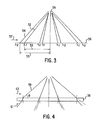
- Figure 3 shows how unequal image heights can be created in a conventional system by two light beams having dissimilar wavelengths.
- light beam 52 having wavelength ⁇ 1 and light beam 54, having wavelength ⁇ 2 ( ⁇ 2 > ⁇ 1) are projected through optics similar to correction optics 30 shown in Figure 2 onto image receiving surface 56, which may be a photoreceptor.
- image receiving surface 56 which may be a photoreceptor.
- the beams are scanned across the image receiving surface 56 in a direction shown by arrow 57 to form images on the image receiving surface 56.
- the beams 52 and 54 when passing through the imaging and correction optics, will be refracted differently from one another because the imaging and correction optics have different indexes of refraction for beams having different wavelengths.
- the present invention provides means for reducing the difference between the image height of each of the images (preferably equalizing the image heights) produced by the dissimilar wavelength light beams, as will be further described below.
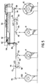
- Figure 4 shows a light transmissive plate 58 for changing (in this example, reducing) an image height of an image produced by a beam having a predetermined wavelength.
- beam 59 is scanned in direction 63 to create an image on an image receiving surface.
- the light transmissive plate 58 will reduce the image height of an image produced by scanning beam 59 in direction 63 by refracting the beam as it passes through the light conductive plate 58.
- the image height will be reduced by a distance 61, as shown in Fig. 4.
- Fig. 4 shows a distance 61, as shown in Fig. 4.
- the reduction in image height is larger at the ends of the scan line (i.e., farther from the optical axis) than at the center of the scan line (i.e., at the optical axis) due to the difference in the angle of incidence ⁇ where the beam passes through light transmissive plate 58.
- the amount of correction required in each light beam increases as the distance from the optical axis increases, as detailed above. Accordingly, by placing light transmissive plate 58 in the path of the light beam having the larger wavelength (e.g., beam 54 in Fig. 3), the image height of its image can be reduced to approximate the image height of the image formed by the beam having the shorter wavelength (e.g., beam 52).
- the change in the image height caused by plate 58 is affected by various factors including the thickness of the light transmissive plate 58, the index of refraction of the light transmissive plate 58 at the specific wavelength of the beam and the angle of incidence of the beam ( ⁇ ) at the specific field position.
- an image height compensating light transmissive plate in the path of each light beam (when the plural light beams have distinct wavelengths), so that the image heights of the resulting images are substantially the same.
- one of the light beams is left uncompensated (for example, the light beam having the shortest wavelength the F ⁇ lens was designed for), while light transmissive plates are included in the paths of the other light beams, these plates being designed to change the image height of the resulting image so that it approximates the image height of the image formed by the uncompensated (but correct) light beam.
- optical filters 36 and 44 may be designed to cause the images formed by the light beams that pass therethrough (i.e., light beams 14 and 20) to have image heights that approximate each other and that approximate the image height of the image formed by light beam 16.
- optical filters in printing devices to separate light beams by wavelength (see, for example, US-A-5,243,359), it has not been suggested to select the thickness and refractive index of the optical filters so that they reduce (preferably minimize) differences between the image heights of images formed by different wavelength light beams.
- Figure 5 shows a second embodiment of the present invention, which produces two pairs of laser beams, each pair of laser beams having dissimilar wavelengths from the other pair of laser beams.
- the polarization of the light beams within each pair is rotated to be different from the polarization of the light of the other pair by, for example, 90° so that the two beams within each pair can be distinguished and thus separated from each other.
- the beams can then be separated by post-polygon optics in accordance with both wavelength and polarization characteristics of the light beams.
- This configuration produces a raster output scanner with four beams that only requires the beams having two dissimilar wavelengths.
- Device 112 scans four laser beams 114, 116, 118 and 120.
- the beams 116 and 118 comprise a first pair of beams having a first wavelength ( ⁇ 1) and the beams 114 and 120 comprise a second pair of beams having a second wavelength ( ⁇ 2) longer than ⁇ 1.
- One beam within each pair of beams has a different polarization from the other beam within each pair of beams (beam 114 has a different polarization from beam 120, and beam 116 has a different polarization from beam 118).
- the beams 114, 116, 118 and 120 are reflected by mirror 60 onto motion compensation optics 62, which corrects for polygon wobble, for example.
- the beams 114, 116, 118 and 120 are then reflected onto mirror 64 and to polarized beam separator 66.
- Polarized beam separator 66 separates the beams by their polarization by reflecting beams 114 and 116, which have a first polarization (P), and passing beams 118 and 120, which have a second polarization (S).
- the polarized beam separator 66 can be, for example, a prism or a device having a polarization selective multiple layer film.
- Substantially equal path lengths are set by adjusting the optical path lengths after the polarized beam separator 66. This may be accomplished by properly positioning mirrors 38, 40, 42, 45, 46, 48 and 50.
- the beams 114, 116, 118 and 120 are directed to the image receiving surfaces 4, 6, 8 and 10 by the mirrors and optical filters as described above in conjunction with Fig. 2.
- this embodiment of the present invention reduces the difference between the image heights of the images produced on image receiving surfaces 4 and 10 and the image heights of the images produced on image receiving surfaces 6 and 8, preferably equalizing the image heights. This is done, as detailed above, by properly setting the thickness and the index of refraction of the optical filters (e.g., glass plates) 36 and 44 to reduce the height of the images produced on each of the image receiving surfaces 4 and 10.
- the optical filters e.g., glass plates
- the invention is applicable to all types of printing devices that use light beams having different wavelengths to form images.
- Such printing devices include facsimile machines, copiers, printers, etc.
- the illustrated printing devices use four light beams, the invention is applicable to any device where one light beam has a wavelength that is different from the wavelength of another beam.
- the invention is applicable to printing devices having two or more light beams.
- the illustrated embodiments direct each light beam to separate imaging surfaces that are separate photoconductive drums.
- the invention also is applicable to printing devices that use a single imaging surface to receive multiple scanned light beams. For example, a single photoreceptor belt that is sensitive to different wavelengths could receive each of the light beams.
- each beam would be directed to different locations on the single imaging surface, although it is possible to direct each light beam to the same location.
- the main feature is that each beam forms its own distinct image, which needs to properly match with the images formed by the other light beams.
Landscapes
- Physics & Mathematics (AREA)
- Engineering & Computer Science (AREA)
- General Physics & Mathematics (AREA)
- Optics & Photonics (AREA)
- Multimedia (AREA)
- Signal Processing (AREA)
- General Engineering & Computer Science (AREA)
- Theoretical Computer Science (AREA)
- Mechanical Optical Scanning Systems (AREA)
- Facsimile Scanning Arrangements (AREA)
- Laser Beam Printer (AREA)
Applications Claiming Priority (2)
| Application Number | Priority Date | Filing Date | Title |
|---|---|---|---|
| US327873 | 1981-12-07 | ||
| US08/327,873 US5563647A (en) | 1994-10-24 | 1994-10-24 | Method and apparatus for reducing differences in image heights of images generated by plural light beams having dissimilar wavelengths |
Publications (3)
| Publication Number | Publication Date |
|---|---|
| EP0710009A2 true EP0710009A2 (de) | 1996-05-01 |
| EP0710009A3 EP0710009A3 (de) | 1996-10-09 |
| EP0710009B1 EP0710009B1 (de) | 2000-05-10 |
Family
ID=23278449
Family Applications (1)
| Application Number | Title | Priority Date | Filing Date |
|---|---|---|---|
| EP95307562A Expired - Lifetime EP0710009B1 (de) | 1994-10-24 | 1995-10-24 | Verfahren und Vorrichtung, um den Unterschied der Bildhöhen von Bildern, die durch mehrere Lichtstrahlen mit verschiedenen Höhen erzeugt werden, zu reduzieren |
Country Status (4)
| Country | Link |
|---|---|
| US (1) | US5563647A (de) |
| EP (1) | EP0710009B1 (de) |
| JP (1) | JP3778970B2 (de) |
| DE (1) | DE69516800T2 (de) |
Cited By (1)
| Publication number | Priority date | Publication date | Assignee | Title |
|---|---|---|---|---|
| EP0817467A3 (de) * | 1996-07-01 | 2000-09-06 | Xerox Corporation | Verfahren und Vorrichtung zur Ausrichtung von Bildern |
Families Citing this family (9)
| Publication number | Priority date | Publication date | Assignee | Title |
|---|---|---|---|---|
| JP2854537B2 (ja) * | 1995-03-29 | 1999-02-03 | 双葉電子工業株式会社 | 感光記録装置 |
| JPH08321929A (ja) * | 1995-05-25 | 1996-12-03 | Fuji Photo Film Co Ltd | 光走査記録装置 |
| US5956070A (en) * | 1995-12-22 | 1999-09-21 | Xerox Corporation | Color xerographic printer with multiple linear arrays of surface emitting lasers with dissimilar polarization states and dissimilar wavelengths |
| US5854705A (en) * | 1997-01-17 | 1998-12-29 | Xerox Corporation | Micropositioned laser source for raster output scanners |
| US7084896B2 (en) * | 2000-03-30 | 2006-08-01 | Pentax Corporation | Multi-beam scanning device |
| KR100846775B1 (ko) * | 2002-05-10 | 2008-07-16 | 삼성전자주식회사 | 칼라 레이저 프린터 |
| US6774923B2 (en) | 2002-05-31 | 2004-08-10 | Lexmark International, Inc. | Dual polygon laser printhead for a color printer |
| KR100970644B1 (ko) * | 2008-05-08 | 2010-07-15 | 엘지전자 주식회사 | 스캐닝 디스플레이 장치 |
| WO2011061824A1 (ja) * | 2009-11-18 | 2011-05-26 | キヤノン株式会社 | 光走査装置 |
Citations (6)
| Publication number | Priority date | Publication date | Assignee | Title |
|---|---|---|---|---|
| US4474422A (en) | 1979-11-13 | 1984-10-02 | Canon Kabushiki Kaisha | Optical scanning apparatus having an array of light sources |
| US4847642A (en) | 1987-01-30 | 1989-07-11 | Canon Kabushiki Kaisha | Electrophotographic apparatus |
| US4903067A (en) | 1987-04-28 | 1990-02-20 | Canon Kabushiki Kaisha | Multiimage forming apparatus |
| US5243359A (en) | 1991-12-19 | 1993-09-07 | Xerox Corporation | Raster output scanner for a multistation xerographic printing system |
| US5341158A (en) | 1992-09-22 | 1994-08-23 | Xerox Corporation | Raster output scanner for a xerographic printing system having laser diodes arranged in a line parallel to the fast scan direction |
| US5343224A (en) | 1992-09-22 | 1994-08-30 | Xerox Corporation | Diode laser multiple output scanning system |
Family Cites Families (9)
| Publication number | Priority date | Publication date | Assignee | Title |
|---|---|---|---|---|
| US2885924A (en) * | 1953-11-17 | 1959-05-12 | S-Hertogenbosch Max Cahen | Optical apparatus for use in accurately positioning printing plates on a printing cylinder |
| US5181137A (en) * | 1988-08-24 | 1993-01-19 | Canon Kabushiki Kaisha | Light scanning apparatus |
| US5068677A (en) * | 1988-09-20 | 1991-11-26 | Minolta Camera Kabushiki Kaisha | Laser scanner with selected plural beam sources |
| JPH03248115A (ja) * | 1990-02-26 | 1991-11-06 | Minolta Camera Co Ltd | マルチビーム光学装置 |
| JP2995925B2 (ja) * | 1991-06-14 | 1999-12-27 | ミノルタ株式会社 | レーザビーム合成方法 |
| US5276463A (en) * | 1992-09-22 | 1994-01-04 | Xerox Corporation | Raster output scanning arrangement for a printing machine |
| US5371526A (en) * | 1992-09-22 | 1994-12-06 | Xerox Corporation | Raster output scanner for a single pass printing system which separates plural laser beams by wavelength and polarization |
| US5325381A (en) * | 1992-12-22 | 1994-06-28 | Xerox Corporation | Multiple beam diode laser output scanning system |
| US5402436A (en) * | 1993-12-29 | 1995-03-28 | Xerox Corporation | Nonmonolithic array structure of multiple beam diode lasers |
-
1994
- 1994-10-24 US US08/327,873 patent/US5563647A/en not_active Expired - Lifetime
-
1995
- 1995-10-12 JP JP26375395A patent/JP3778970B2/ja not_active Expired - Fee Related
- 1995-10-24 EP EP95307562A patent/EP0710009B1/de not_active Expired - Lifetime
- 1995-10-24 DE DE69516800T patent/DE69516800T2/de not_active Expired - Lifetime
Patent Citations (6)
| Publication number | Priority date | Publication date | Assignee | Title |
|---|---|---|---|---|
| US4474422A (en) | 1979-11-13 | 1984-10-02 | Canon Kabushiki Kaisha | Optical scanning apparatus having an array of light sources |
| US4847642A (en) | 1987-01-30 | 1989-07-11 | Canon Kabushiki Kaisha | Electrophotographic apparatus |
| US4903067A (en) | 1987-04-28 | 1990-02-20 | Canon Kabushiki Kaisha | Multiimage forming apparatus |
| US5243359A (en) | 1991-12-19 | 1993-09-07 | Xerox Corporation | Raster output scanner for a multistation xerographic printing system |
| US5341158A (en) | 1992-09-22 | 1994-08-23 | Xerox Corporation | Raster output scanner for a xerographic printing system having laser diodes arranged in a line parallel to the fast scan direction |
| US5343224A (en) | 1992-09-22 | 1994-08-30 | Xerox Corporation | Diode laser multiple output scanning system |
Cited By (1)
| Publication number | Priority date | Publication date | Assignee | Title |
|---|---|---|---|---|
| EP0817467A3 (de) * | 1996-07-01 | 2000-09-06 | Xerox Corporation | Verfahren und Vorrichtung zur Ausrichtung von Bildern |
Also Published As
| Publication number | Publication date |
|---|---|
| EP0710009B1 (de) | 2000-05-10 |
| US5563647A (en) | 1996-10-08 |
| DE69516800D1 (de) | 2000-06-15 |
| EP0710009A3 (de) | 1996-10-09 |
| JP3778970B2 (ja) | 2006-05-24 |
| JPH08194179A (ja) | 1996-07-30 |
| DE69516800T2 (de) | 2000-09-21 |
Similar Documents
| Publication | Publication Date | Title |
|---|---|---|
| US5243359A (en) | Raster output scanner for a multistation xerographic printing system | |
| US6061079A (en) | Laser beam printer with a common scanning optical system | |
| EP0604077B1 (de) | Ausgangsabtastsystem mit mehrstrahligen Laserdioden | |
| US6239828B1 (en) | Image formation device for forming a color image composed of plural colors | |
| JPH1195140A (ja) | マルチビーム露光装置 | |
| US5956070A (en) | Color xerographic printer with multiple linear arrays of surface emitting lasers with dissimilar polarization states and dissimilar wavelengths | |
| EP0710009B1 (de) | Verfahren und Vorrichtung, um den Unterschied der Bildhöhen von Bildern, die durch mehrere Lichtstrahlen mit verschiedenen Höhen erzeugt werden, zu reduzieren | |
| US5371526A (en) | Raster output scanner for a single pass printing system which separates plural laser beams by wavelength and polarization | |
| EP0589652B1 (de) | Rasterabtastvorrichtung für ein xerographisches Drucksystem mit Laserdioden, die in einer Reihe angeordnet sind, parallel zur Schnellabtastrichtung | |
| US5617133A (en) | Method and apparatus for adjusting orientation of light beams in a raster scanning system | |
| US5691761A (en) | Method and apparatus for multi-channel printing in a raster output scanning system | |
| US5343224A (en) | Diode laser multiple output scanning system | |
| US6873445B2 (en) | Optical multi-beam scanning device and image forming apparatus | |
| US5995267A (en) | Time division multiplexing multiple beam raster output scanning system | |
| US5627579A (en) | Raster scanning optical system and method for adjusting scan line locations on a photoreceptor | |
| JP2006079052A (ja) | 光走査装置及び画像形成装置 | |
| JP5712709B2 (ja) | 光走査装置及び画像形成装置 | |
| EP0782928B1 (de) | Farbxerographischer Drucker mit vielfachen linearen Reihen von oberflächenemittierenden Lasern mit gleichen Wellenlängen | |
| EP0781663B1 (de) | Farbxerographischer Drucker mit vielfachen linearen Reihen von oberflächenemittierenden Lasern mit verschiedenen Wellenlängen | |
| JP2004301974A (ja) | 走査光学装置 | |
| JP2005250103A (ja) | マルチビーム走査光学装置及びそれを用いた画像形成装置 | |
| JPH10186252A (ja) | 光走査装置および画像形成装置 | |
| JP2003177345A (ja) | 光ビーム走査装置及び画像形成装置 | |
| JPH0829713A (ja) | マルチビーム走査光学装置 | |
| JPH0391778A (ja) | カラー画像形成装置 |
Legal Events
| Date | Code | Title | Description |
|---|---|---|---|
| PUAI | Public reference made under article 153(3) epc to a published international application that has entered the european phase |
Free format text: ORIGINAL CODE: 0009012 |
|
| AK | Designated contracting states |
Kind code of ref document: A2 Designated state(s): DE FR GB |
|
| PUAL | Search report despatched |
Free format text: ORIGINAL CODE: 0009013 |
|
| AK | Designated contracting states |
Kind code of ref document: A3 Designated state(s): DE FR GB |
|
| 17P | Request for examination filed |
Effective date: 19970409 |
|
| 17Q | First examination report despatched |
Effective date: 19981218 |
|
| GRAG | Despatch of communication of intention to grant |
Free format text: ORIGINAL CODE: EPIDOS AGRA |
|
| GRAG | Despatch of communication of intention to grant |
Free format text: ORIGINAL CODE: EPIDOS AGRA |
|
| GRAH | Despatch of communication of intention to grant a patent |
Free format text: ORIGINAL CODE: EPIDOS IGRA |
|
| GRAH | Despatch of communication of intention to grant a patent |
Free format text: ORIGINAL CODE: EPIDOS IGRA |
|
| GRAA | (expected) grant |
Free format text: ORIGINAL CODE: 0009210 |
|
| AK | Designated contracting states |
Kind code of ref document: B1 Designated state(s): DE FR GB |
|
| REF | Corresponds to: |
Ref document number: 69516800 Country of ref document: DE Date of ref document: 20000615 |
|
| ET | Fr: translation filed | ||
| PLBE | No opposition filed within time limit |
Free format text: ORIGINAL CODE: 0009261 |
|
| STAA | Information on the status of an ep patent application or granted ep patent |
Free format text: STATUS: NO OPPOSITION FILED WITHIN TIME LIMIT |
|
| 26N | No opposition filed | ||
| REG | Reference to a national code |
Ref country code: GB Ref legal event code: IF02 |
|
| PGFP | Annual fee paid to national office [announced via postgrant information from national office to epo] |
Ref country code: GB Payment date: 20140924 Year of fee payment: 20 |
|
| PGFP | Annual fee paid to national office [announced via postgrant information from national office to epo] |
Ref country code: DE Payment date: 20140924 Year of fee payment: 20 Ref country code: FR Payment date: 20141021 Year of fee payment: 20 |
|
| REG | Reference to a national code |
Ref country code: DE Ref legal event code: R071 Ref document number: 69516800 Country of ref document: DE |
|
| REG | Reference to a national code |
Ref country code: GB Ref legal event code: PE20 Expiry date: 20151023 |
|
| PG25 | Lapsed in a contracting state [announced via postgrant information from national office to epo] |
Ref country code: GB Free format text: LAPSE BECAUSE OF EXPIRATION OF PROTECTION Effective date: 20151023 |