EP0712058A1 - Appareil de formation d'images - Google Patents
Appareil de formation d'images Download PDFInfo
- Publication number
- EP0712058A1 EP0712058A1 EP95307726A EP95307726A EP0712058A1 EP 0712058 A1 EP0712058 A1 EP 0712058A1 EP 95307726 A EP95307726 A EP 95307726A EP 95307726 A EP95307726 A EP 95307726A EP 0712058 A1 EP0712058 A1 EP 0712058A1
- Authority
- EP
- European Patent Office
- Prior art keywords
- carriage
- drum
- image forming
- image
- main body
- Prior art date
- Legal status (The legal status is an assumption and is not a legal conclusion. Google has not performed a legal analysis and makes no representation as to the accuracy of the status listed.)
- Granted
Links
- 238000004140 cleaning Methods 0.000 claims description 9
- 108091008695 photoreceptors Proteins 0.000 description 45
- 230000002093 peripheral effect Effects 0.000 description 17
- 238000012546 transfer Methods 0.000 description 16
- 230000015572 biosynthetic process Effects 0.000 description 7
- 230000033001 locomotion Effects 0.000 description 7
- 238000011161 development Methods 0.000 description 6
- 238000012423 maintenance Methods 0.000 description 5
- 239000000463 material Substances 0.000 description 5
- 238000000034 method Methods 0.000 description 5
- 230000033228 biological regulation Effects 0.000 description 3
- 230000006835 compression Effects 0.000 description 3
- 238000007906 compression Methods 0.000 description 3
- VYPSYNLAJGMNEJ-UHFFFAOYSA-N Silicium dioxide Chemical compound O=[Si]=O VYPSYNLAJGMNEJ-UHFFFAOYSA-N 0.000 description 2
- 230000007423 decrease Effects 0.000 description 2
- 230000003247 decreasing effect Effects 0.000 description 2
- 230000001105 regulatory effect Effects 0.000 description 2
- 230000000630 rising effect Effects 0.000 description 2
- 238000000926 separation method Methods 0.000 description 2
- GWEVSGVZZGPLCZ-UHFFFAOYSA-N Titan oxide Chemical compound O=[Ti]=O GWEVSGVZZGPLCZ-UHFFFAOYSA-N 0.000 description 1
- 230000002411 adverse Effects 0.000 description 1
- 230000015556 catabolic process Effects 0.000 description 1
- 239000003795 chemical substances by application Substances 0.000 description 1
- 239000003086 colorant Substances 0.000 description 1
- 238000006731 degradation reaction Methods 0.000 description 1
- 238000007599 discharging Methods 0.000 description 1
- 230000005484 gravity Effects 0.000 description 1
- 238000009413 insulation Methods 0.000 description 1
- 230000003287 optical effect Effects 0.000 description 1
- 230000010355 oscillation Effects 0.000 description 1
- 239000000049 pigment Substances 0.000 description 1
- 229920000728 polyester Polymers 0.000 description 1
- 238000012545 processing Methods 0.000 description 1
- 239000011347 resin Substances 0.000 description 1
- 229920005989 resin Polymers 0.000 description 1
- 239000000377 silicon dioxide Substances 0.000 description 1
- OGIDPMRJRNCKJF-UHFFFAOYSA-N titanium oxide Inorganic materials [Ti]=O OGIDPMRJRNCKJF-UHFFFAOYSA-N 0.000 description 1
- 230000001960 triggered effect Effects 0.000 description 1
- 238000011179 visual inspection Methods 0.000 description 1
- 229910000859 α-Fe Inorganic materials 0.000 description 1
Images



Classifications
-
- G—PHYSICS
- G03—PHOTOGRAPHY; CINEMATOGRAPHY; ANALOGOUS TECHNIQUES USING WAVES OTHER THAN OPTICAL WAVES; ELECTROGRAPHY; HOLOGRAPHY
- G03G—ELECTROGRAPHY; ELECTROPHOTOGRAPHY; MAGNETOGRAPHY
- G03G21/00—Arrangements not provided for by groups G03G13/00 - G03G19/00, e.g. cleaning, elimination of residual charge
- G03G21/16—Mechanical means for facilitating the maintenance of the apparatus, e.g. modular arrangements
- G03G21/18—Mechanical means for facilitating the maintenance of the apparatus, e.g. modular arrangements using a processing cartridge, whereby the process cartridge comprises at least two image processing means in a single unit
- G03G21/1839—Means for handling the process cartridge in the apparatus body
- G03G21/1857—Means for handling the process cartridge in the apparatus body for transmitting mechanical drive power to the process cartridge, drive mechanisms, gears, couplings, braking mechanisms
- G03G21/1864—Means for handling the process cartridge in the apparatus body for transmitting mechanical drive power to the process cartridge, drive mechanisms, gears, couplings, braking mechanisms associated with a positioning function
Definitions
- the present invention relates to an image forming apparatus, in which a charging means, an image exposure means and a developing means are arranged around an image forming body, a toner image is formed on the peripheral surface of the image forming body when the image forming body is rotated, and then, the toner image is transferred onto a recording sheet.
- an image forming apparatus specifically, in a conventional electrophotographic copier for office use, or an image recording apparatus used for terminal equipment, the following apparatus, for easily carrying out jam clearance operations or maintenance operations, are widely known.
- an apparatus in which a cartridge for incorporating a photoreceptor and developing units therein, is removed when a side door of the apparatus main body is opened, and the surface of the conveyance path for the transfer material is exposed.
- a clamshell type apparatus in which the apparatus main body is separated into an upper and a lower main body, and the surface of the conveyance path for the transfer material is exposed.
- the conveyance path of the recording sheet is used as a separation line to open and close the upper portion of the apparatus with respect to the lower portion of the apparatus.
- a portion of the photoreceptor which is opposed to the transfer unit is largely exposed, and a possibility occurs in which operator's hands easily touch the portion, and the surface of the photoreceptor is stained.
- An object of the present invention is to provide a color image forming apparatus from which a photoreceptor and developing units can be removed without being touched with the operator's hands or other units, and the surface of the conveyance path for the transfer material is opened so that jam clearance or maintenance of the apparatus can be safely and easily carried out.
- the image forming apparatus is provided with a carriage, which can be pulled out from its installed position.
- the carriage supports a cartridge, including an image forming body, in its pull-out position, and fixes the cartridge at a position, at which an image can be formed, at the installed position of the carriage.
- the image forming apparatus is provided with a carriage, which can be pulled out from its installed position.
- the carriage supports a cartridge, including an image forming body, at its pull-out position, and fixes the cartridge to a position, at which an image can be formed, at the installed position of the carriage. Further, when the carriage is located at its installed position, it forms at least a portion of the upper surface of the apparatus main body.
- Fig. 1 is a sectional view showing a structure of a color image forming apparatus according to the present invention.
- Fig. 2 is a plan view showing a layout of the color image forming apparatus.
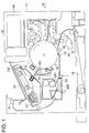
- Fig. 3 is a sectional structural view showing a pull-out position of a drum carriage.
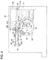
- Fig. 4 is a sectional view of a primary portion, showing the structure when the drum carriage is installed.
- Fig.5 is a sectional view of a primary portion, showing the structure when the drum carriage is pulled out.
- numeral 10 is a photoreceptor drum, which is an image forming body, with an OPC photoreceptor coated on the drum.
- the photoreceptor drum is electrically grounded, and driven clockwise.
- Numeral 12 is a scorotron charger which uniformly charges the peripheral surface of the photoreceptor drum 10 with a potential voltage of V H by a corona discharge using a grid, having the potential voltage of V G , and a corona discharge wire.
- an exposure by a PCL 11 using a light emitting diode, or the like is carried out so that the hysteresis of the photoreceptor due to previous printing are eliminated, and the peripheral surface of the photoreceptor is electrically discharged.
- an image exposure is carried out by an image exposure means 13 according to an image signal.
- the optical path of a light beam emitted from a light source composed of a laser diode, not shown in the drawing, is bent by a reflection mirror 132 after the light beam passes through a rotating polygonal mirror 131, an f ⁇ lens, or the like.
- scanning is carried out, and a latent image is formed on the photoreceptor by the rotation of the photoreceptor drum 10 (subsidiary scanning).
- a character portion is exposed, and a reversal latent image, in which the character portion has a lower potential voltage V L , is formed.
- a developing sleeve 141 in which a magnet is housed, and which is rotated while retaining developer thereon.
- Developer is composed of carrier and toner, wherein the carrier has ferrite core, and an insulation resin is coated around the core.
- Toner is made of polyester as a main material, and pigments corresponding to colors, charge control agents, silica, titanium oxide, etc., are added to the main material.
- the developer is regulated to a layer thickness of 100 through 600 ⁇ m on the developing sleeve 141 by a layer forming means, and conveyed to a developing area.
- a gap 0.2 through 1.0 mm is formed between the developing sleeve 141 and the photoreceptor drum 10 in the developing area, which is larger than the layer thickness of the developer, and an AC bias voltage of V AC and a DC bias voltage of V DC are superimposed on this gap. Since V DC , V H , and the electric charge of toner have the same polarity, the toner, which is triggered to separate from the carrier by the V AC , does not adhere to the V H portion, the potential voltage (an absolute value) of which is higher than that of V DC , but adheres to the V L portion, the potential voltage of which is lower than that of V DC , and thereby, a latent image is visualized (reverse development).
- the system After the first color visualizing operation, the system enters into the second color image formation process.
- the peripheral surface of the photoreceptor drum 1 is uniformly charged again by the scorotron charger 12, and a latent image according to the second color image data is formed by the image exposure means 13.
- the discharging operation conducted by the PCL 11 in the first color image formation process is not conducted because the toner, adhered to the first color image portion, scatters due to the sudden decrease of the surrounding potential voltage.
- the whole peripheral surface of the photoreceptor drum 10 is uniformly charged again so that the photoreceptor has the potential voltage of V H .
- the same latent image as in the first color is formed on a portion in which a first color image does not exist, and a latent image is developed.
- a latent image having the potential voltage of V M ' is formed by light-shielding due to the adhered first color toner, and electric charges of the toner itself, and development is conducted corresponding to the potential difference between V DC and V M '.
- the third and the fourth color image forming processes are carried out, and a four-color visualized image is formed on the peripheral surface of the photoreceptor drum 10.
- Recording sheet P conveyed from a sheet feed cassette through a semi-circular roller 16, temporarily stops, and then, the recording sheet P is conveyed to the transfer area by the rotation of a sheet feed roller 17 in timed relationship with the transfer unit.
- a transfer roller 18 is brought into pressure contact with the peripheral surface of the photoreceptor drum 10 in timed relationship with the transfer, the recording sheet P, fed from the sheet feed cassette 15, is sandwiched between the transfer roller 18 and the peripheral surface of the photoreceptor drum 10, and a multi-color image is simultaneously transferred onto the sheet P.
- the recording sheet P is discharged by a peak-electrode 19, having a narrow gap with respect to the surface of the photoreceptor drum 10, and the sheet P is separated from the peripheral surface of the photoreceptor drum 10.
- the recording sheet P is conveyed to a fixing unit 20, and a toner is fused by the heat of a thermal roller 201 and pressure of a pressure roller 202.
- the recording sheet P is delivered outside the apparatus with a delivery roller 21.
- the above-described transfer roller 18 is withdrawn from the peripheral surface of the photoreceptor drum 10 after passage of the recording sheet P, and the transfer roller 18 is ready for the next toner image formation.
- the photoreceptor drum 10 is discharged again by the PCL 11 and charged again by the charger 12, and enters into the next image formation process.
- the above-described blade 221 is immediately withdrawn from the peripheral surface of the photoreceptor drum 10 after cleaning the surface of the photoreceptor drum 10.
- Fig. 2 is a plan view of each unit, of which the above-described apparatus is composed, and shows a layout of each unit of the apparatus.
- the side indicated by an arrow corresponds to the front surface of the apparatus, that is, a side surface on an operation side.
- the apparatus main body has two vertical side panels 73 and 74, between which a writing unit, which is the image exposure means 13, the photoreceptor drum 10, a developing unit 400 in which a plurality of developing devices 14 are housed, a fixing unit 20, and a DC power source unit 500 are incorporated.
- a driving system 600, a formatter 700 for decoding a printer command, a control circuit boards 800 for the sequence control of mechanical operations are housed on the outside of the side panel 73.
- a toner replenishing means 140 which is connected to each developing device 14 housed in the developing unit 400, is accommodated.
- the photoreceptor drum 10, the charger 12 and the cleaning unit 22 are integrated and incorporated into a drum cartridge 30.
- the drum cartridge 30 is integrated and incorporated into a drum carriage 40, together with the developing units 14, the toner replenishing means 140, the front panel 71 and the upper surface panel 72.
- the drum carriage 40 can move horizontally from its installed position in the apparatus main body as shown by a broken line in Fig. 3, and can be positioned at its pull-out position.
- the drum cartridge 30 and the upper panel 72 follow the movement of the drum carriage 40, and are withdrawn from a position, at which an image can be formed, (shown by a broken line). Then, the conveyance path of the recording sheet P is fully exposed to the upper surface of the apparatus. Further, the transfer roller 18, the peak-electrode 19, the charger 12 and the cleaning unit 22, which are integrated and incorporated into the drum cartridge 30, are fully exposed to the upper surface of the apparatus.
- the drum carriage 40 In Fig. 4, the drum carriage 40 is located at its installed position, and the drum cartridge 30 is fixed to the image forming apparatus. In Fig. 5, the drum carriage 40 is moved to its pull-out position, and the drum cartridge 30 is withdrawn from the image formation position and is supported on the drum carriage 40 without being fixed to the drum carriage 40.
- the drum cartridge 30 side is shown by a one-dotted chain line
- the drum carriage 40 side is shown by a two-dotted chain line.
- a first guide member 50 composed of an upper rail 51 and a lower rail 52, and a guide roller 53 are provided, facing each other, inside each of the side panels 73 and 74 in the apparatus main body.
- the drum carriage 40 has a plate member 41 provided with a roller 42, on both side surfaces.
- the drum carriage is supported when the roller 42 is engaged with the guide member 50, and the plate member 41 itself is engaged with a guide roller 53.
- the drum carriage 40 In the installed position of the drum carriage 40, the drum carriage 40 is located at a position at which the roller 42 has moved to the end of an inclined surface 52A of the front end of the lower rail 52, by the weight of the drum carriage 40.
- a cutout portion 41A provided at the rear end of the plate member 41 is engaged with the guide roller 53, the drum carriage 40 is vertically and horizontally positioned.
- a regulation pin 43 protruding from the front surface of the carriage 40 is engaged with a regulation hole on a collision plate 54 provided between the side panels, the vertical movement of the carriage is regulated.
- the position of the photoreceptor drum 10 is set when the drum shaft 10A is engaged with the opening portion 61A of the guide plate 61, and the engagement lever 62 comes into pressure contact with the drum shaft 10A.
- the left and right compression springs 44 provided on the front surface of the drum carriage 40 press a raised portion 30A of the drum cartridge 30 main body and press it onto the collision plate 54, and thereby, the drum cartridge 30 is set at the position at which an image can be formed.
- collision rollers 141A of the urged developing units 14 are brought into pressure contact with the peripheral surface of the photoreceptor drum 10, which is positioned as described above, and a predetermined development gap is formed between the peripheral surface of the photoreceptor drum 10 and that of the developing sleeve 141.
- engagement of gears and electrical connections of electric contacts provided between the drum cartridge 30 side and the apparatus main body side are automatically conducted, and the supply of the motive power and electric power, and the control, which are necessary for image formation, can be conducted.
- the roller 42 of the plate member 41 is moved inside the guide member 50, and when a lower edge of the cutout portion 41A slides onto the guide roller 53, the drum carriage 40 is pulled out toward the front of the apparatus main body, as shown in Fig. 5.
- the roller 42 rises along the inclined surface 52A of the lower rail 52.
- the regulation pin 43 is disengaged from the collision plate 54, while the drum carriage 40 is rising approximately horizontally to a predetermined height, and the drum carriage 40 is pulled forward.
- an engagement portion 41B formed on the lower edge portion of the plate member 41 is simultaneously engaged with the guide roller 53, and the drum carriage 40 is stopped.
- each developing unit 14 is withdrawn from the range of the pressure-contact operation with respect to the photoreceptor drum 10.
- the drum cartridge 30 is released from the pressure, applied by the compression spring 44, and a receiving portion 30B, formed in an upper portion of the cartridge 30, is directly supported by the plate member 41 when the drum carriage 40 rises.
- a receiving portion 30B formed in an upper portion of the cartridge 30, is directly supported by the plate member 41 when the drum carriage 40 rises.
- the above-described height H1 to which the drum carriage 40 rises at the start of its movement is set such that the height H2, required for avoiding the frictional contact between the photoreceptor drum 10 and the transfer roller 18 by the rising motion of the photoreceptor drum 10 when the photoreceptor drum 10 is horizontally moved, is added to the height of a gap provided between the drum cartridge 30 and the drum carriage 40.
- the height H1 is preferably set to not less than 6 mm.
- the drum carriage 40 When the drum carriage 40, at its pull-out position, is sufficiently forced from the front surface of the apparatus, shown in Fig. 5, the plate member 41 is disengaged from the guide roller 53, and slides horizontally. The drum carriage 40 is lowered by the height corresponding to the above-described height H1 at the final stage of its movement, and the plate member 41 is engaged again with the guide roller 53. Then, the drum carriage 40 is installed again at the position as shown in Fig. 4. As described above, the drum cartridge 40 can be stably installed in the apparatus main body by utilizing gravity.
- the drum cartridge 30 slides horizontally, being driven by the movement of the drum carriage 40.
- the drum shaft 10A is lowered, being guided by the guide plate 61, in timed relationship with the lowering of the drum cartridge 40, and forcibly rotates the engagement lever 62.
- the drum shaft 10A is fixed at the position shown in Fig. 4.
- the drum cartridge 30 is set again to the image forming position by the pressure of the compression spring 44 of the drum carriage 40.
- the lowered amount of the drum carriage 40 corresponds to the above-described height H1.
- the lowered amount of the drum cartridge 30 corresponds to the above-described height H2. Accordingly, a gap is formed between the drum cartridge 30 and the drum carriage 40. Therefore, the drum cartridge 30 is not restrained by the drum carriage 40, and is set to a predetermined image forming position.
- a drum-shaped image forming body is explained, however, a belt-like image forming body, in which a belt is provided between rollers, is also included in the present invention.
- a drum carriage including an image forming body, a charging means, a developing means, and a cleaning means, is pulled out from the apparatus by relatively simple operations, so that the conveyance path for the recording sheet can be fully opened.
- jam clearance processing for the recording sheet can be easily carried out, and when the drum carriage is pulled out from the apparatus, the drum cartridge can be simply pulled out.
- a transfer means, a separation means, and a charger and a cleaning unit accommodated in the drum cartridge are fully exposed to the upper surface of the apparatus. Accordingly, maintenance, including cleaning operations and replacement operations for each means and device, and visual inspection, etc., can be easily conducted.
- the drum cartridge when the drum carriage and the drum cartridge are installed in the apparatus, the drum cartridge, the accuracy of which is required most in the relationship with an image exposure means, etc., is fixed to the apparatus main body under the condition that the drum cartridge is separated from the drum carriage, so that high accuracy can be maintained with respect to each device. Accordingly, an image forming apparatus is provided, in which a satisfactory image is constantly assured, and maintenance operations for each unit can be easily made, and which is also highly practical. Further, since a toner replenishment means, integrally provided in the drum carriage, is incorporated in the upper portion of each developing unit, the toner replenishment path can be simplified, and toner can be stably replenished.
Landscapes
- Engineering & Computer Science (AREA)
- Computer Vision & Pattern Recognition (AREA)
- Physics & Mathematics (AREA)
- General Physics & Mathematics (AREA)
- Electrophotography Configuration And Component (AREA)
Applications Claiming Priority (3)
| Application Number | Priority Date | Filing Date | Title |
|---|---|---|---|
| JP27797894 | 1994-11-11 | ||
| JP27797894 | 1994-11-11 | ||
| JP277978/94 | 1994-11-11 |
Publications (2)
| Publication Number | Publication Date |
|---|---|
| EP0712058A1 true EP0712058A1 (fr) | 1996-05-15 |
| EP0712058B1 EP0712058B1 (fr) | 1999-10-13 |
Family
ID=17590926
Family Applications (1)
| Application Number | Title | Priority Date | Filing Date |
|---|---|---|---|
| EP95307726A Expired - Lifetime EP0712058B1 (fr) | 1994-11-11 | 1995-10-30 | Appareil de formation d'images |
Country Status (2)
| Country | Link |
|---|---|
| US (1) | US5579086A (fr) |
| EP (1) | EP0712058B1 (fr) |
Cited By (1)
| Publication number | Priority date | Publication date | Assignee | Title |
|---|---|---|---|---|
| EP0779561A1 (fr) * | 1995-12-12 | 1997-06-18 | Konica Corporation | Récipient de développateur et dispositif de remplissage de développateur |
Families Citing this family (3)
| Publication number | Priority date | Publication date | Assignee | Title |
|---|---|---|---|---|
| US5758232A (en) * | 1995-10-24 | 1998-05-26 | Konica Corporation | Image forming apparatus having cartridge for developing devices |
| KR100633097B1 (ko) * | 2005-07-22 | 2006-10-11 | 삼성전자주식회사 | 화상형성 프로세스모듈 및 그것을 구비한 화상형성장치 |
| JP7006094B2 (ja) * | 2017-09-28 | 2022-01-24 | ブラザー工業株式会社 | 画像形成装置 |
Citations (5)
| Publication number | Priority date | Publication date | Assignee | Title |
|---|---|---|---|---|
| JPS5784477A (en) * | 1980-11-14 | 1982-05-26 | Canon Inc | Mounting-dismounting device for image holding body |
| JPS60101550A (ja) * | 1983-11-08 | 1985-06-05 | Minolta Camera Co Ltd | 電子写真複写機 |
| EP0370455A2 (fr) * | 1988-11-21 | 1990-05-30 | Konica Corporation | Appareil à copier à couleurs avec cartouche de traitement amovible |
| EP0411825A2 (fr) * | 1989-07-29 | 1991-02-06 | Konica Corporation | Appareil en deux parties pour la formation d'images électrophotographique |
| EP0639801A1 (fr) * | 1993-08-20 | 1995-02-22 | Konica Corporation | Appareil de formation d'images en couleurs muni d'une unité de procédé et d'une cartouche de matériau de développement en couleurs |
Family Cites Families (4)
| Publication number | Priority date | Publication date | Assignee | Title |
|---|---|---|---|---|
| JPS60132456A (ja) * | 1983-12-21 | 1985-07-15 | Toshiba Corp | 画像形成装置 |
| GB8715481D0 (en) * | 1987-07-01 | 1987-08-05 | Xerox Corp | Electrostatographic machine |
| JPH02262673A (ja) * | 1989-04-03 | 1990-10-25 | Konica Corp | カラー画像形成装置 |
| US5486898A (en) * | 1993-07-14 | 1996-01-23 | Konica Corporation | Color image forming apparatus with photoreceptor protector |
-
1995
- 1995-10-27 US US08/549,401 patent/US5579086A/en not_active Expired - Fee Related
- 1995-10-30 EP EP95307726A patent/EP0712058B1/fr not_active Expired - Lifetime
Patent Citations (5)
| Publication number | Priority date | Publication date | Assignee | Title |
|---|---|---|---|---|
| JPS5784477A (en) * | 1980-11-14 | 1982-05-26 | Canon Inc | Mounting-dismounting device for image holding body |
| JPS60101550A (ja) * | 1983-11-08 | 1985-06-05 | Minolta Camera Co Ltd | 電子写真複写機 |
| EP0370455A2 (fr) * | 1988-11-21 | 1990-05-30 | Konica Corporation | Appareil à copier à couleurs avec cartouche de traitement amovible |
| EP0411825A2 (fr) * | 1989-07-29 | 1991-02-06 | Konica Corporation | Appareil en deux parties pour la formation d'images électrophotographique |
| EP0639801A1 (fr) * | 1993-08-20 | 1995-02-22 | Konica Corporation | Appareil de formation d'images en couleurs muni d'une unité de procédé et d'une cartouche de matériau de développement en couleurs |
Non-Patent Citations (2)
| Title |
|---|
| PATENT ABSTRACTS OF JAPAN vol. 006, no. 168 (P - 139) 2 September 1982 (1982-09-02) * |
| PATENT ABSTRACTS OF JAPAN vol. 009, no. 250 (P - 394) 8 October 1985 (1985-10-08) * |
Cited By (2)
| Publication number | Priority date | Publication date | Assignee | Title |
|---|---|---|---|---|
| EP0779561A1 (fr) * | 1995-12-12 | 1997-06-18 | Konica Corporation | Récipient de développateur et dispositif de remplissage de développateur |
| US5722020A (en) * | 1995-12-12 | 1998-02-24 | Konica Corporation | Developer container and developer supplying apparatus |
Also Published As
| Publication number | Publication date |
|---|---|
| US5579086A (en) | 1996-11-26 |
| EP0712058B1 (fr) | 1999-10-13 |
Similar Documents
| Publication | Publication Date | Title |
|---|---|---|
| EP0276910B1 (fr) | Unité de traitement et appareil de formation d'image en couleur l'utilisant | |
| US6738590B2 (en) | Image forming apparatus with detachable image forming unit assembly | |
| US7567769B2 (en) | Electrophotographic color image forming apparatus | |
| US5471284A (en) | Image forming apparatus having toner depletion detection feature | |
| US5752137A (en) | Multi-color image forming apparatus having a plurality of detachable units | |
| US5758232A (en) | Image forming apparatus having cartridge for developing devices | |
| US5493366A (en) | Image forming apparatus | |
| US8626008B2 (en) | Electrophotographic image forming apparatus with removed developer accommodating container for receiving developer cleaned from an image bearing member | |
| US5486898A (en) | Color image forming apparatus with photoreceptor protector | |
| EP0639801B1 (fr) | Appareil de formation d'images en couleurs muni d'une unité de procédé et d'une cartouche de matériau de développement en couleurs | |
| US5335052A (en) | Image recording apparatus with belt-type transfer device | |
| US6366748B1 (en) | Image forming unit with high positioning and rotating accuracy and image forming apparatus using the same | |
| US5579086A (en) | Image forming apparatus with removable photoreceptor carriage | |
| US12393134B2 (en) | Movable member and image forming apparatus | |
| US5585892A (en) | Image forming apparatus with positioning member of frame engaging shaft of roller of photosensitive belt | |
| JPH09319174A (ja) | 画像形成装置 | |
| JP3416834B2 (ja) | 画像形成装置 | |
| US6535704B1 (en) | Upgradeable and easily serviceable imaging systems with a removable module and methods for using the same | |
| US5245394A (en) | Image forming apparatus having an openable conveyance path | |
| JPH07152302A (ja) | カラー画像形成装置 | |
| JPH0619229A (ja) | プロセスカートリッジ | |
| JPH07152303A (ja) | カラー画像形成装置 | |
| JPH09160465A (ja) | 画像形成装置 | |
| JPH09127808A (ja) | 画像形成装置 | |
| JPH09160464A (ja) | 画像形成装置 |
Legal Events
| Date | Code | Title | Description |
|---|---|---|---|
| PUAI | Public reference made under article 153(3) epc to a published international application that has entered the european phase |
Free format text: ORIGINAL CODE: 0009012 |
|
| 17P | Request for examination filed |
Effective date: 19960223 |
|
| AK | Designated contracting states |
Kind code of ref document: A1 Designated state(s): GB |
|
| 17Q | First examination report despatched |
Effective date: 19980303 |
|
| GRAG | Despatch of communication of intention to grant |
Free format text: ORIGINAL CODE: EPIDOS AGRA |
|
| GRAG | Despatch of communication of intention to grant |
Free format text: ORIGINAL CODE: EPIDOS AGRA |
|
| GRAH | Despatch of communication of intention to grant a patent |
Free format text: ORIGINAL CODE: EPIDOS IGRA |
|
| GRAH | Despatch of communication of intention to grant a patent |
Free format text: ORIGINAL CODE: EPIDOS IGRA |
|
| RBV | Designated contracting states (corrected) |
Designated state(s): GB |
|
| REG | Reference to a national code |
Ref country code: DE Ref legal event code: 8566 |
|
| GRAA | (expected) grant |
Free format text: ORIGINAL CODE: 0009210 |
|
| AK | Designated contracting states |
Kind code of ref document: B1 Designated state(s): GB |
|
| PLBE | No opposition filed within time limit |
Free format text: ORIGINAL CODE: 0009261 |
|
| STAA | Information on the status of an ep patent application or granted ep patent |
Free format text: STATUS: NO OPPOSITION FILED WITHIN TIME LIMIT |
|
| 26N | No opposition filed | ||
| REG | Reference to a national code |
Ref country code: GB Ref legal event code: IF02 |
|
| PGFP | Annual fee paid to national office [announced via postgrant information from national office to epo] |
Ref country code: GB Payment date: 20131030 Year of fee payment: 19 |
|
| GBPC | Gb: european patent ceased through non-payment of renewal fee |
Effective date: 20141030 |
|
| PG25 | Lapsed in a contracting state [announced via postgrant information from national office to epo] |
Ref country code: GB Free format text: LAPSE BECAUSE OF NON-PAYMENT OF DUE FEES Effective date: 20141030 |