EP0712143B1 - Condensateur électrique à double couche et méthode de fabrication d'une électrode pour celui-ci - Google Patents
Condensateur électrique à double couche et méthode de fabrication d'une électrode pour celui-ci Download PDFInfo
- Publication number
- EP0712143B1 EP0712143B1 EP95117269A EP95117269A EP0712143B1 EP 0712143 B1 EP0712143 B1 EP 0712143B1 EP 95117269 A EP95117269 A EP 95117269A EP 95117269 A EP95117269 A EP 95117269A EP 0712143 B1 EP0712143 B1 EP 0712143B1
- Authority
- EP
- European Patent Office
- Prior art keywords
- acicular
- electrically
- particles
- electrode material
- recited
- Prior art date
- Legal status (The legal status is an assumption and is not a legal conclusion. Google has not performed a legal analysis and makes no representation as to the accuracy of the status listed.)
- Expired - Lifetime
Links
Images
Classifications
-
- H—ELECTRICITY
- H01—ELECTRIC ELEMENTS
- H01G—CAPACITORS; CAPACITORS, RECTIFIERS, DETECTORS, SWITCHING DEVICES, LIGHT-SENSITIVE OR TEMPERATURE-SENSITIVE DEVICES OF THE ELECTROLYTIC TYPE
- H01G11/00—Hybrid capacitors, i.e. capacitors having different positive and negative electrodes; Electric double-layer [EDL] capacitors; Processes for the manufacture thereof or of parts thereof
- H01G11/22—Electrodes
- H01G11/30—Electrodes characterised by their material
- H01G11/32—Carbon-based
- H01G11/38—Carbon pastes or blends; Binders or additives therein
-
- H—ELECTRICITY
- H01—ELECTRIC ELEMENTS
- H01G—CAPACITORS; CAPACITORS, RECTIFIERS, DETECTORS, SWITCHING DEVICES, LIGHT-SENSITIVE OR TEMPERATURE-SENSITIVE DEVICES OF THE ELECTROLYTIC TYPE
- H01G11/00—Hybrid capacitors, i.e. capacitors having different positive and negative electrodes; Electric double-layer [EDL] capacitors; Processes for the manufacture thereof or of parts thereof
- H01G11/22—Electrodes
- H01G11/30—Electrodes characterised by their material
- H01G11/32—Carbon-based
- H01G11/42—Powders or particles, e.g. composition thereof
-
- H—ELECTRICITY
- H01—ELECTRIC ELEMENTS
- H01G—CAPACITORS; CAPACITORS, RECTIFIERS, DETECTORS, SWITCHING DEVICES, LIGHT-SENSITIVE OR TEMPERATURE-SENSITIVE DEVICES OF THE ELECTROLYTIC TYPE
- H01G11/00—Hybrid capacitors, i.e. capacitors having different positive and negative electrodes; Electric double-layer [EDL] capacitors; Processes for the manufacture thereof or of parts thereof
- H01G11/22—Electrodes
- H01G11/30—Electrodes characterised by their material
- H01G11/32—Carbon-based
- H01G11/44—Raw materials therefor, e.g. resins or coal
-
- Y—GENERAL TAGGING OF NEW TECHNOLOGICAL DEVELOPMENTS; GENERAL TAGGING OF CROSS-SECTIONAL TECHNOLOGIES SPANNING OVER SEVERAL SECTIONS OF THE IPC; TECHNICAL SUBJECTS COVERED BY FORMER USPC CROSS-REFERENCE ART COLLECTIONS [XRACs] AND DIGESTS
- Y02—TECHNOLOGIES OR APPLICATIONS FOR MITIGATION OR ADAPTATION AGAINST CLIMATE CHANGE
- Y02E—REDUCTION OF GREENHOUSE GAS [GHG] EMISSIONS, RELATED TO ENERGY GENERATION, TRANSMISSION OR DISTRIBUTION
- Y02E60/00—Enabling technologies; Technologies with a potential or indirect contribution to GHG emissions mitigation
- Y02E60/13—Energy storage using capacitors
Definitions
- Small button-type double-layer capacitors having two electrically-conductive electrodes impregnated with an electrolyte and separated by an ion permeable material are known in the art.
- the electrode material is activated carbon fiber cloth.
- the pole volume of the electrode material is high, there is little contact between the fibers, and contact resistance is high.
- chopped fibers of activated carbon are mixed with a fluoropolymer and a conductivity enhancing material and molded or pressed into sheet-form to serve as the electrodes. This type of electrode material also had electrical resistance higher than desirable for the purpose.
- Japanese Laid-Open Patent Application No. 63-107011 discloses an electrode material for double-layer capacitors made of discs stamped from a sheet formed of a mixture of particles of activated carbon, carbon black, and polytetrafluoroethylene. This type of electrode material requires an increased polytetrafluoroethylene binder content to develop adequate strength and, consequently, also has electrical resistance higher than desirable for the purpose.
- US-A-4,862,328 discloses an electric double-layer capacitor having the features of the pre-characterizing part of claim 1.
- the electrically-conductive electrode material layers comprise a PTFE composition containing fine carbon powder, e.g. pulverized carbon fibers.
- the material is prepared in the form of electrode sheet material. When the sheet material is extruded with the conductive particles contained therein, the particles will extend in a planar direction of the sheet upon exiting the extruder.
- the present invention provides an improved double-layer capacitor which is defined by the features of claim 1 and in which the improvement is a planar layered electrode assembly which has low electrical resistance in the direction normal to the planar direction of the assembly (thickness direction), and which has high electric storage capacity.
- the electrode material is easily and inexpensively produced by a process in which acicular electrically-conductive particles are blended with a binder, oriented by extrusion means, and cut to form planar electrode discs or plates in which the acicular particles are oriented as nearly perpendicular as possible to the flat surfaces of the electrode.
- porous as used herein, is meant a structure defining interconnected passages and pathways throughout a material.
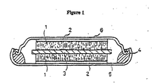
- the improved double-layer capacitor consists of an open-top casing in which is disposed a porous layered electrode assembly.
- the electrode assembly consists of two layers of porous electrically-conductive electrode material having between them, in contacting relationship, a layer of ion permeable material.
- the electrode material consists of a porous polymeric matrix containing electrically-conductive particles.
- One layer of the electrode material is electrically-connected to the casing; the second layer of the electrode material is electrically-connected to a casing cover.
- the electrode assembly is impregnated with an electrolyte.
- the casing cover is separated and electrically-insulated from the casing, and is also sealed to the casing, by a dielectric sealant interposed between the cover and the casing.
- each electrode material layer comprises a polytetrafluoroethylene (PTFE) binder composition containing acicular electrically-conductive particles, or a blend of acicular and non-acicular electrically-conductive particles, the particles having a size and concentration in the polytetrafluoroethylene composition whereby the acicular particles can be directionally oriented within the polytetrafluoroethylene composition, substantially in one direction, by extrusion means.
- PTFE polytetrafluoroethylene
- the electrode material layers of the assembly have planar shapes, typically discs or plates, wherein the acicular particles are substantially oriented in the direction perpendicular to the planar direction of the electrode material layer, i.e., the acicular particles are oriented as much as possible in the thickness direction of the discs or plates.
- the dielectric sealant 4 used to join and seal the cover to the casing, and to electrically insulate the cover from the casing can be selected from among many commercially available materials. Selection is made according to the compatibility of the sealant with the electrolyte, ease of application, cost, and other considerations. Synthetic polymers, such as polyurethanes, polyolefins, fluoropolymers, and the like, can be used; as can natural rubbers; or synthetic rubbers, including silicone rubbers, fluoroelastomers, fluorosilicone rubbers, and the like, depending on the electrolyte used.
- the separator 3 sandwiched between the electrodes 2 can also be made of commercially available materials. Films or membranes of porous polymeric dielectric material can be used which, when coated or impregnated with an electrolyte, permit movement of ions across them.
- porous membranes including woven and non-woven forms, of polyethylene, polypropylene, polyethersulfone, fluoropolymers, fiberglass, and the like, can be used, and are selected according to their stability and compatibility with the electrolyte of the capacitor, Polyethersulfone, for instance is stable in an alkaline aqueous electrolyte, but cannot be used in an acidic aqueous electrolyte.
- the separator membranes are thin, 200 micrometers or less thick, more preferably in the range of 10 to 100 micrometers thick.
- the membrane resistance in an electrolyte should be in the range 0.1 to 2.0 ohm-cm.
- the electrode 1 of the instant invention comprises a polytetrafluoroethylene composition containing acicular electrically-conductive particles, or a blend of acicular and non-acicular electrically-conductive particles.
- the acicular particles in the electrode material are oriented, as nearly as possible, in the direction of electric current flow into or out of the electrode to minimize the electrical path length and reduce electrical resistance to the charging or discharging current flow.
- Non-acicular electrically-conductive particles in the composition provide the benefit of increased surface area for electrolyte contact, which is directly related to the amount of charge which can be stored, and provide relatively short electrical pathways to and between the acicular particles for most efficient charge transfer of the capacitor.
- Suitable acicular electrically-conductive particles include carbon fibers, activated carbon fibers, graphite whiskers, metal fibers, and the like.
- the carbon fibers and activated carbon fibers can be based on phenol, rayon, acrylic, or pitch.
- Suitable metal fibers can be platinum, gold, aluminum, or the like.
- the fiber diameters should be in the range 0.1 to 50 micrometers, and their lengths should be in the range 1 to 1000 micrometers. If the fibers are too short they are difficult to orient in one direction and, furthermore, provide a relatively long electrical path length and relatively low electrical conductivity. On the other hand, if the fibers are too long, uniform mixing and further processing is difficult.
- electrically-conductive non-acicular particles can be blended with the acicular particles.
- Suitable electrically-conductive non-acicular particles include carbon particles, activated carbon particles, and metal particles.
- the carbon particles are inclusive of graphite particles and carbon blacks.
- the activated carbon particles can be of the types described above and further include activated carbon based on coconut shell.
- the metal particles can be powders of the metals described above.
- the non-acicular particles should be highly electroconductive and provide a large amount of surface area; in the case of the carbon and activated carbon particles, the surface area should be 1000 m 2 /gram or more.
- acicular and non-acicular particles When acicular and non-acicular particles are included in the polytetrafluoroethylene composition they should be present in an amount of 5 to 97 weight percent, preferably 50 to 97 weight percent, and more preferably 70 to 95 weight percent; thus, the polytetrafluoroethylene concentration of the composition will be in the amount of 3 to 95 weight percent, preferably 3 to 50 weight percent, and more preferably 5 to 30 weight percent.
- the polytetrafluoroethylene composition containing electrically-conductive acicular particles, or a blend of acicular and non-acicular electrically-conductive particles can be formed using polytetrafluoroethylene paste-forming, or paste-extrusion, processes.
- a fine powder PTFE resin is combined with electrically-conductive particles through one of two methods.
- fine powder PTFE resin, electrically-conductive particles, and a lubricating liquid are blended together to form a consistent mixture.
- Suitable lubricants including water, alcohols, naphtha, mineral spirits, kerosene or other aliphatic hydrocarbon liquids, have been used in polytetrafluoroethylene paste-forming processes, and are known in the art. Conventional mixing methods such as rolling or tumbling can be used.
- an aqueous dispersion of PTFE resin is used.
- the electrically-conductive particles are mixed with an aqueous dispersion of PTFE particles.
- the mixture is co-coagulated, i.e., the PTFE resin is coagulated in the presence of the electrically-conductive particles by rapid shearing of the aqueous dispersion, or through destabilization of the aqueous dispersion with salt, acid, polyethylene imine, or the like.
- a coagulum of fine powder PTFE resin and electrically-conductive particles is formed and subsequently dried. When dry, a liquid lubricant is added to the coagulum and mixed to form a consistent mixture.
- Electrodes of the present invention can be prepared from the extruded article, or from the extruded and stretched article, whether heat treated or not, by cutting the rod-shaped article in a direction normal to the extrusion direction to obtain planar slices in which the acicular particles are substantially oriented in the extrusion direction.
- the bulk density of the electrode material is typically about 0.3 to 1.2 g/cc, but may be more or less depending on the amount and specific gravity of the particles present in the PTFE compositions.
- the specific gravity of platinum is 21.4 g/cc and that of carbon is about 2 g/cc.
- the thickness of the planar slices will vary depending on the designed capacitance of the capacitor, but will generally be about 0.1 mm to 3 mm thick.
- ⁇ -butyrolactone acetonitrile, dimethylformamide, 1,2-dimethoxyethane, sulfolane, nitromethane, or other polar organic solvent.
- an aqueous solution electrolyte containing inorganic acid, inorganic base, or inorganic salt as a solute can be used. Of these latter, sulfuric acid, tetrafluoroboric acid, or other such acid; or potassium hydroxide or sodium hydroxide is preferable for obtaining high electrical conductivity.
- the electrolyte can be added to the material forming the electrode assembly at any convenient time in the process, so long as the material is free of water. Generally, the electrolyte is added to the extruded article, or to the extruded and stretched article, before cutting; or to the electrode assembly after it has been formed.
- Each of the double-layer capacitors described hereinbelow was charged at a constant voltage of 2.4 volts for 30 minutes, after which it was discharged at a constant current of 1 mA, and its capacity calculated.
- the impedance was measured by an alternating current two-terminal method at a frequency of I kHz. The results are shown in Table 1.
- a double-layer capacitor of the invention was prepared as follows:
- Activated carbon fibers (Type ACC-507-15, manufactured by Nippon Kynol Co.) with an average fiber diameter of 9-11 micrometers were pulverized.
- the activated carbon fibers had a specific surface area of 1500 m 2 /gram, as measured by the BET method. Fibers having a fiber length of 1 mm or less were collected and used in a PTFE composition.
- the capacitor was assembled as follows:
- a 1 mm thick electrode was cut from the extruded article described above, in a direction perpendicular to the extrusion direction.
- the electrode was placed on the inside bottom of an austenitic stainless steel casing having a diameter of about 14 mm.
- the casing and its cover also stainless steel, had their interior surface covered with an electrically-conductive paste, and were then dried.
- the casing, with the electrode in place, was further dried under vacuum at a temperature of 150°C for ten hours, after which they were moved to a nitrogen-filled dry box (dew point: - minus 50°C) to prevent accumulation of moisture on the materials.
- the electrode was fully impregnated with the electrolyte described above.
- a capacitor was prepared as described in Example 1, except that the PTFE composition consisted of 70 wt.% non-acicular particles of coconut shell-based activated carbon (specific surface area - 1500 m 2 /gram), 20 wt.% of phenol -based carbon fibers, and 10 wt.% PTFE.
Landscapes
- Engineering & Computer Science (AREA)
- Power Engineering (AREA)
- Chemical & Material Sciences (AREA)
- Materials Engineering (AREA)
- Microelectronics & Electronic Packaging (AREA)
- Electric Double-Layer Capacitors Or The Like (AREA)
Claims (16)
- Condensateur électrique à double couche se composant de :dans lequel une dite couche de matériau d'électrode (1) est électriquement connectée audit boítier (5) et l'autre dite couche de matériau d'électrode (1) est électriquement connectée audit couvercle de boítier (6), et dans lequel ledit ensemble formant électrode est imprégné d'un électrolyte ;la) un boítier (5) découvert ayant au moins un côté et un fond ;(b) un ensemble formant électrode à couche poreuse disposé dans ledit boítier, ledit ensemble formant électrode se composant de deux couches (1) de matériau d'électrode poreux électroconducteur ayant entre elles, en relation d'aboutissement, un séparateur (3) se composant d'une couche de matériau perméable aux ions,
ledit matériau d'électrode se composant d'une matrice polymère poreuse extrudée contenant des particules électroconductrices ;(c) un couvercle de boítier (6), ledit couvercle de boítier (6) étant électriquement isolé de et hermétique audit boítier grâce à un matériau d'étanchéité diélectrique (14) interposé entre ledit couvercle (6) et ledit boítier (5) ;
caractérisé en ce que chacune desdites couches de matériau d'électrode poreux électroconducteur comprend une composition à base de polytétrafluoroéthylène extrudé contenant des particules aciculaires électroconductrices, lesdites particules aciculaires ayant une taille et une concentration dans la composition à base de polytétrafluoroéthylène qui donnent une orientation directionnelle auxdites particules grâce à des moyens d'extrusion, lesdites particules aciculaires étant orientées dans une direction approximativement perpendiculaire à la direction planaire de ladite couche de matériau d'électrode. - Condensateur électrique à double couche selon la revendication 1, dans lequel lesdites particules aciculaires électroconductrices ont un diamètre moyen dans la plage allant de 0,1 à 50 micromètres et une longueur dans la plage allant de 1 à 1000 micromètres.
- Condensateur électrique à double couche selon la revendication 2, dans lequel lesdites particules aciculaires électroconductrices sont choisies parmi le groupe se composant de particules de charbon et de particules de charbon actif.
- Condensateur électrique à double couche selon la revendication 3, dans lequel lesdites particules aciculaires de charbon actif sont formées par carbonisation et activation de fibres provenant du groupe se composant de fibres à base de phénol, de fibres de polyacrylonitrile et de fibres à base de rayonne.
- Condensateur électrique à double couche selon la revendication 2, dans lequel ladite composition à base de polytétrafluoréthylène contient en outre des particules électroconductrices non aciculaires.
- Condensateur électrique à double couche selon la revendication 5, dans lequel lesdites particules aciculaires et non aciculaires électroconductrices sont choisies parmi le groupe se composant de particules de charbon et de particules de charbon actif.
- Condensateur électrique à double couche selon la revendication 6, dans lequel lesdites particules aciculaires de charbon actif sont formées par carbonisation et activation de fibres provenant du groupe se composant de fibres à base de phénol, de fibres de polyacrylonitrile et de fibres à base de rayonne.
- Méthode de fabrication d'un matériau d'électrode pour un condensateur à double couche comprenant les étapes consistant à :(a) mélanger une résine de polytétrafluoréthylène conjointement avec des particules aciculaires électroconductrices afin de former une composition à base de polytétrafluoréthylène ;(b) lubrifier la composition à base de polytétrafluoréthylène à l'aide d'un lubrifiant ;(c) extruder la composition à base de polytétrafluoréthylène lubrifiée par l'intermédiaire d'une filière ayant une entrée conique, orientant de cette manière lesdites particules aciculaires dans la direction d'extrusion et formant un article en forme de tige allongé ;(d) découper ledit article en forme de tige dans une direction perpendiculaire à la direction d'extrusion pour former des disques ou plaques d'électrode planaires (1), où lesdites particules aciculaires sont orientées dans une direction approximativement perpendiculaire à la direction planaire du matériau d'électrode.
- Méthode de fabrication d'un matériau d'électrode selon la revendication 8, dans laquelle lesdites particules aciculaires électroconductrices ont un diamètre moyen dans la plage allant de 0,1 à 50 micromètres et une longueur dans la plage allant de 1 à 1000 micromètres.
- Méthode de fabrication d'un matériau d'électrode selon la revendication 9, dans lequel lesdites particules aciculaires électroconductrices sont choisies parmi le groupe se composant de particules de charbon et de particules de charbon actif.
- Méthode de fabrication d'un matériau d'électrode selon la revendication 10, comprenant en outre l'étape consistant à mélanger des particules non aciculaires électroconductrices avec une résine de polytétrafluoréthylène et des particules aciculaires électroconductrices pour former ladite composition.
- Méthode de fabrication d'un matériau d'électrode selon la revendication 11, dans laquelle lesdites particules aciculaires et non aciculaires électroconductrices sont choisies parmi le groupe se composant de particules de charbon et de particules de charbon actif.
- Méthode de fabrication d'un matériau d'électrode selon la revendication 9, comprenant en outre l'étape consistant à étirer ledit article en forme de tige dans la direction d'extrusion d'une quantité dans la plage allant de 1,1 à 5 fois la longueur d'origine dudit article.
- Méthode de fabrication d'un matériau d'électrode selon la revendication 10, comprenant en outre l'étape consistant à étirer ledit article en forme de tige dans la direction d'extrusion d'une quantité dans la plage allant de 1,1 à 5 fois la longueur d'origine dudit article.
- Méthode de fabrication d'un matériau d'électrode selon la revendication 11, comprenant en outre l'étape consistant à étirer ledit article en forme de tige dans la direction d'extrusion d'une quantité dans la plage allant de 1,1 à 5 fois la longueur d'origine dudit article.
- Méthode de fabrication d'un matériau d'électrode selon la revendication 12, comprenant en outre l'étape consistant à étirer ledit article en forme de tige dans la direction d'extrusion d'une quantité dans la plage allant de 1,1 à 5 fois la longueur d'origine dudit article.
Applications Claiming Priority (3)
| Application Number | Priority Date | Filing Date | Title |
|---|---|---|---|
| JP269641/94 | 1994-11-02 | ||
| JP26964194 | 1994-11-02 | ||
| JP6269641A JPH08138978A (ja) | 1994-11-02 | 1994-11-02 | 電気二重層コンデンサとその電極の製造方法 |
Publications (3)
| Publication Number | Publication Date |
|---|---|
| EP0712143A2 EP0712143A2 (fr) | 1996-05-15 |
| EP0712143A3 EP0712143A3 (fr) | 1999-04-21 |
| EP0712143B1 true EP0712143B1 (fr) | 2003-03-26 |
Family
ID=17475183
Family Applications (1)
| Application Number | Title | Priority Date | Filing Date |
|---|---|---|---|
| EP95117269A Expired - Lifetime EP0712143B1 (fr) | 1994-11-02 | 1995-11-02 | Condensateur électrique à double couche et méthode de fabrication d'une électrode pour celui-ci |
Country Status (4)
| Country | Link |
|---|---|
| US (1) | US5682288A (fr) |
| EP (1) | EP0712143B1 (fr) |
| JP (1) | JPH08138978A (fr) |
| DE (1) | DE69530045D1 (fr) |
Cited By (1)
| Publication number | Priority date | Publication date | Assignee | Title |
|---|---|---|---|---|
| CN102893353A (zh) * | 2010-05-18 | 2013-01-23 | 英派尔科技开发有限公司 | 采用相变材料的超级电容器 |
Families Citing this family (89)
| Publication number | Priority date | Publication date | Assignee | Title |
|---|---|---|---|---|
| US5862035A (en) * | 1994-10-07 | 1999-01-19 | Maxwell Energy Products, Inc. | Multi-electrode double layer capacitor having single electrolyte seal and aluminum-impregnated carbon cloth electrodes |
| US8455710B2 (en) * | 1997-09-22 | 2013-06-04 | Argentum Medical, Llc | Conductive wound dressings and methods of use |
| JP3628822B2 (ja) * | 1996-10-25 | 2005-03-16 | パイロットプレシジョン株式会社 | フィルム状電極およびその製造方法 |
| FR2759211B1 (fr) * | 1997-02-06 | 1999-04-30 | Electricite De France | Supercondensateur du type double couche comprenant un electrolyte organique liquide |
| JPH10275748A (ja) * | 1997-03-31 | 1998-10-13 | Nec Corp | 電気二重層コンデンサ |
| US6246568B1 (en) * | 1997-06-16 | 2001-06-12 | Matsushita Electric Industrial Co., Ltd. | Electric double-layer capacitor and method for manufacturing the same |
| EP0917166B1 (fr) | 1997-09-22 | 2007-08-01 | Japan Gore-Tex, Inc. | Condensateur électrique à double couche et son procédé de fabrication |
| JP3719570B2 (ja) * | 1997-10-20 | 2005-11-24 | 株式会社パワーシステム | 電気二重層コンデンサ |
| US6349027B1 (en) | 1997-10-29 | 2002-02-19 | Asahi Glass Company, Ltd. | Electric double layer capacitor |
| US6383427B2 (en) | 1997-12-24 | 2002-05-07 | Asahi Glass Company, Ltd. | Process for producing an electric double layer capacitor electrode |
| US6341057B1 (en) | 1997-11-05 | 2002-01-22 | Danionics A/S | Double layer capacitor and its manufacturing method |
| EP0964416A4 (fr) * | 1997-11-11 | 2005-03-02 | Np Predpr Eksin | Condensateur a couche electrique double |
| JP3791180B2 (ja) * | 1998-04-23 | 2006-06-28 | 旭硝子株式会社 | 電気二重層キャパシタ用電極及び該電極を有する電気二重層キャパシタ |
| WO2000004559A1 (fr) * | 1998-07-17 | 2000-01-27 | Murata Manufacturing Co., Ltd. | Procede de production d'une composition conductrice et composition conductrice |
| JP2000049055A (ja) * | 1998-07-27 | 2000-02-18 | Asahi Glass Co Ltd | 電気二重層キャパシタ用電極及び電気二重層キャパシタ |
| US6212061B1 (en) * | 1998-09-29 | 2001-04-03 | General Electric Company | Sealing an ultracapacitor |
| US6304426B1 (en) * | 1998-09-29 | 2001-10-16 | General Electric Company | Method of making an ultracapacitor electrode |
| DE60037472T2 (de) * | 1999-02-05 | 2008-12-04 | Kureha Corporation | Zusammensetzung zur Herstellung von Elektroden, Aktiv-Kohle Elektrode und elektrischer Doppelschichtkondensator |
| US20030062259A1 (en) * | 1999-05-10 | 2003-04-03 | Naofumi Mushiake | Electrochemical device and process for manufacturing same |
| US6261717B1 (en) | 1999-05-28 | 2001-07-17 | The Gillette Company | Battery having an electrode within another electrode |
| US6342317B1 (en) | 1999-07-21 | 2002-01-29 | The Gillette Company | Battery |
| JP2001076971A (ja) * | 1999-09-03 | 2001-03-23 | Nec Corp | 電気二重層コンデンサおよびその製造方法 |
| US6410187B1 (en) | 1999-09-09 | 2002-06-25 | The Gillette Company | Primary alkaline battery |
| DE19948742C1 (de) * | 1999-10-09 | 2000-12-28 | Dornier Gmbh | Elektrochemischer Kondensator, insb. Doppelschichtkondensator oder Superkondensator |
| JP2001267187A (ja) * | 2000-03-22 | 2001-09-28 | Ngk Insulators Ltd | 電気二重層コンデンサ用分極性電極 |
| US6631074B2 (en) | 2000-05-12 | 2003-10-07 | Maxwell Technologies, Inc. | Electrochemical double layer capacitor having carbon powder electrodes |
| US6627252B1 (en) | 2000-05-12 | 2003-09-30 | Maxwell Electronic Components, Inc. | Electrochemical double layer capacitor having carbon powder electrodes |
| DE10053276C1 (de) * | 2000-10-27 | 2002-01-10 | Dornier Gmbh | Elektrochemischer Kondensator |
| IL155790A0 (en) * | 2000-11-09 | 2003-12-23 | Foc Frankenburg Oil Company Es | A supercapacitor and a method of manufacturing such a supercapacitor |
| DE10114107A1 (de) * | 2001-03-23 | 2002-10-02 | Epcos Ag | Schichtelektrode für elektrochemische Bauelemente und elektrochemischer Doppelschichtkondensator mit der Schichtelektrode |
| JP2002289481A (ja) * | 2001-03-28 | 2002-10-04 | Kyocera Corp | 活性炭質構造体およびそれを用いた電気二重層コンデンサ |
| WO2002091410A1 (fr) * | 2001-05-07 | 2002-11-14 | Cooper Technologies Company | Separateurs de dispositifs electrochimiques microfabriques |
| US6813139B2 (en) * | 2001-11-02 | 2004-11-02 | Maxwell Technologies, Inc. | Electrochemical double layer capacitor having carbon powder electrodes |
| US6643119B2 (en) | 2001-11-02 | 2003-11-04 | Maxwell Technologies, Inc. | Electrochemical double layer capacitor having carbon powder electrodes |
| KR20050014875A (ko) * | 2002-06-24 | 2005-02-07 | 미쓰비시 쥬시 가부시끼가이샤 | 도전성 수지필름, 집전체 및 그것들의 제조 방법 |
| US7061749B2 (en) * | 2002-07-01 | 2006-06-13 | Georgia Tech Research Corporation | Supercapacitor having electrode material comprising single-wall carbon nanotubes and process for making the same |
| JP3873844B2 (ja) * | 2002-08-06 | 2007-01-31 | 松下電器産業株式会社 | 電気二重層コンデンサ用電解液の評価方法 |
| US7352558B2 (en) * | 2003-07-09 | 2008-04-01 | Maxwell Technologies, Inc. | Dry particle based capacitor and methods of making same |
| US7342770B2 (en) * | 2003-07-09 | 2008-03-11 | Maxwell Technologies, Inc. | Recyclable dry particle based adhesive electrode and methods of making same |
| US7508651B2 (en) | 2003-07-09 | 2009-03-24 | Maxwell Technologies, Inc. | Dry particle based adhesive and dry film and methods of making same |
| US7791860B2 (en) | 2003-07-09 | 2010-09-07 | Maxwell Technologies, Inc. | Particle based electrodes and methods of making same |
| US7295423B1 (en) * | 2003-07-09 | 2007-11-13 | Maxwell Technologies, Inc. | Dry particle based adhesive electrode and methods of making same |
| US20100014215A1 (en) * | 2004-04-02 | 2010-01-21 | Maxwell Technologies, Inc. | Recyclable dry particle based electrode and methods of making same |
| JP4713068B2 (ja) * | 2003-08-01 | 2011-06-29 | パナソニック株式会社 | 非水電解質二次電池 |
| US7920371B2 (en) | 2003-09-12 | 2011-04-05 | Maxwell Technologies, Inc. | Electrical energy storage devices with separator between electrodes and methods for fabricating the devices |
| JP2005116762A (ja) * | 2003-10-07 | 2005-04-28 | Fujitsu Ltd | 半導体装置の保護方法及び半導体装置用カバー及び半導体装置ユニット及び半導体装置の梱包構造 |
| US7495349B2 (en) * | 2003-10-20 | 2009-02-24 | Maxwell Technologies, Inc. | Self aligning electrode |
| JP2005166975A (ja) * | 2003-12-03 | 2005-06-23 | Sanyo Electric Co Ltd | 電気二重層コンデンサ、電解質電池及びこれらの製造方法 |
| US7090946B2 (en) * | 2004-02-19 | 2006-08-15 | Maxwell Technologies, Inc. | Composite electrode and method for fabricating same |
| US7384433B2 (en) | 2004-02-19 | 2008-06-10 | Maxwell Technologies, Inc. | Densification of compressible layers during electrode lamination |
| US7227737B2 (en) | 2004-04-02 | 2007-06-05 | Maxwell Technologies, Inc. | Electrode design |
| US7245478B2 (en) | 2004-08-16 | 2007-07-17 | Maxwell Technologies, Inc. | Enhanced breakdown voltage electrode |
| JP2006173302A (ja) * | 2004-12-15 | 2006-06-29 | Sanyo Electric Co Ltd | 電気二重層キャパシタ |
| US7440258B2 (en) | 2005-03-14 | 2008-10-21 | Maxwell Technologies, Inc. | Thermal interconnects for coupling energy storage devices |
| US7492574B2 (en) | 2005-03-14 | 2009-02-17 | Maxwell Technologies, Inc. | Coupling of cell to housing |
| JP2006310064A (ja) * | 2005-04-28 | 2006-11-09 | Sanyo Electric Co Ltd | 蓄電デバイス |
| JP2006344918A (ja) * | 2005-06-07 | 2006-12-21 | Dynic Corp | 電気二重層キャパシタ用電極材 |
| EP1936642B1 (fr) * | 2005-10-11 | 2014-04-30 | Showa Denko K.K. | Condensateur double couche électrique |
| JP4878881B2 (ja) * | 2006-03-17 | 2012-02-15 | 日本ゴア株式会社 | 電気二重層キャパシタ用電極および電気二重層キャパシタ |
| JP2007273906A (ja) * | 2006-03-31 | 2007-10-18 | Sanyo Electric Co Ltd | 電気二重層キャパシタ |
| JP2007288059A (ja) * | 2006-04-19 | 2007-11-01 | Nisshinbo Ind Inc | 電気二重層キャパシタ |
| US8518573B2 (en) | 2006-09-29 | 2013-08-27 | Maxwell Technologies, Inc. | Low-inductive impedance, thermally decoupled, radii-modulated electrode core |
| US20080201925A1 (en) | 2007-02-28 | 2008-08-28 | Maxwell Technologies, Inc. | Ultracapacitor electrode with controlled sulfur content |
| US7933114B2 (en) * | 2007-08-31 | 2011-04-26 | Corning Incorporated | Composite carbon electrodes useful in electric double layer capacitors and capacitive deionization and methods of making the same |
| DE102008010563A1 (de) | 2008-02-22 | 2009-09-03 | Süd-Chemie AG | Verwendung von Aktivkohlen als Superkondensator |
| KR101056734B1 (ko) * | 2008-06-20 | 2011-08-12 | 주식회사 아모그린텍 | 고밀도 슈퍼 커패시터의 전극 및 그의 제조방법 |
| EP2443070A4 (fr) | 2009-06-16 | 2013-06-19 | Cambrian Innovation Inc | Systèmes et dispositifs pour traiter et surveiller de l'eau, des eaux usées et autres matières biodégradables |
| WO2010150534A1 (fr) * | 2009-06-23 | 2010-12-29 | クラレケミカル株式会社 | Condensateur continu, procédé de production d'eau désionisée, et dispositif de production d'eau déionisée |
| CA2783256C (fr) | 2009-12-08 | 2018-06-12 | Justin Buck | Capteurs utilisant des microbes pour la surveillance de l'environnement |
| US11101465B2 (en) | 2017-03-28 | 2021-08-24 | Enevate Corporation | Reaction barrier between electrode active material and current collector |
| US20110204284A1 (en) * | 2010-02-25 | 2011-08-25 | Renee Kelly Duncan | Carbon electrode batch materials and methods of using the same |
| US9240578B2 (en) * | 2010-03-09 | 2016-01-19 | Samsung Sdi Co., Ltd. | Secondary battery |
| US20110267740A1 (en) * | 2010-04-29 | 2011-11-03 | Shrisudersan Jayaraman | Packaging for electrochemically active materials, devices made therefrom, and methods of making the same |
| US8331076B2 (en) | 2010-07-16 | 2012-12-11 | Ut-Battelle, Llc | Clad fiber capacitor and method of making same |
| JP5873085B2 (ja) | 2010-07-21 | 2016-03-01 | カンブリアン イノベーション エルエルシー | 廃水を処理するための生物−電気化学的システムおよび酸性ガスを処理するための方法 |
| US10851003B2 (en) | 2010-07-21 | 2020-12-01 | Matthew Silver | Denitrification and pH control using bio-electrochemical systems |
| US9963790B2 (en) | 2010-10-19 | 2018-05-08 | Matthew Silver | Bio-electrochemical systems |
| US10388943B2 (en) | 2010-12-22 | 2019-08-20 | Enevate Corporation | Methods of reducing occurrences of short circuits and/or lithium plating in batteries |
| US9583757B2 (en) * | 2010-12-22 | 2017-02-28 | Enevate Corporation | Electrodes, electrochemical cells, and methods of forming electrodes and electrochemical cells |
| US9397338B2 (en) | 2010-12-22 | 2016-07-19 | Enevate Corporation | Electrodes, electrochemical cells, and methods of forming electrodes and electrochemical cells |
| BR112013028414A2 (pt) * | 2011-05-03 | 2017-01-24 | Axion Power Int Inc | processo para a fabricação de folha de carbono para eletrodo |
| KR20120129569A (ko) * | 2011-05-20 | 2012-11-28 | 삼성전기주식회사 | 하이브리드 커패시터 |
| EP3242352A1 (fr) | 2011-06-14 | 2017-11-08 | Cambrian Innovation, Inc. | Procédé pour déterminer la demande biochimique en oxygène |
| WO2016002930A1 (fr) * | 2014-07-04 | 2016-01-07 | 株式会社佐藤工務所 | Procédé de production d'électrode polarisable pour condensateurs électriques à double couche, électrode polarisable pour condensateurs électriques à double couche et condensateur électrique à double couche |
| JP6558725B2 (ja) * | 2014-07-04 | 2019-08-14 | 島根県 | 電気二重層キャパシタ用分極性電極の製造方法及び、電気二重層キャパシタ |
| US12334542B2 (en) | 2017-12-07 | 2025-06-17 | Enevate Corporation | Solid film as binder for battery electrodes |
| US10686214B2 (en) | 2017-12-07 | 2020-06-16 | Enevate Corporation | Sandwich electrodes and methods of making the same |
| US11133498B2 (en) | 2017-12-07 | 2021-09-28 | Enevate Corporation | Binding agents for electrochemically active materials and methods of forming the same |
| JP7419050B2 (ja) * | 2019-12-16 | 2024-01-22 | 日立Astemo株式会社 | パワーモジュール、電力変換装置、およびパワーモジュールの製造方法 |
Family Cites Families (3)
| Publication number | Priority date | Publication date | Assignee | Title |
|---|---|---|---|---|
| JPH07105316B2 (ja) | 1985-08-13 | 1995-11-13 | 旭硝子株式会社 | 電気二重層コンデンサ用分極性電極及びその製造方法 |
| JPH0770449B2 (ja) * | 1987-06-24 | 1995-07-31 | 松下電器産業株式会社 | 分極性電極の製造法 |
| JPH03152916A (ja) * | 1989-11-09 | 1991-06-28 | Isuzu Motors Ltd | 電気二重層コンデンサとその電極製造方法 |
-
1994
- 1994-11-02 JP JP6269641A patent/JPH08138978A/ja not_active Withdrawn
-
1995
- 1995-10-31 US US08/550,849 patent/US5682288A/en not_active Expired - Lifetime
- 1995-11-02 EP EP95117269A patent/EP0712143B1/fr not_active Expired - Lifetime
- 1995-11-02 DE DE69530045T patent/DE69530045D1/de not_active Expired - Lifetime
Cited By (3)
| Publication number | Priority date | Publication date | Assignee | Title |
|---|---|---|---|---|
| CN102893353A (zh) * | 2010-05-18 | 2013-01-23 | 英派尔科技开发有限公司 | 采用相变材料的超级电容器 |
| US9123477B2 (en) | 2010-05-18 | 2015-09-01 | Empire Technology Development Llc | Ultracapacitors employing phase change materials |
| CN102893353B (zh) * | 2010-05-18 | 2016-03-16 | 英派尔科技开发有限公司 | 采用相变材料的超级电容器 |
Also Published As
| Publication number | Publication date |
|---|---|
| DE69530045D1 (de) | 2003-04-30 |
| EP0712143A3 (fr) | 1999-04-21 |
| JPH08138978A (ja) | 1996-05-31 |
| EP0712143A2 (fr) | 1996-05-15 |
| US5682288A (en) | 1997-10-28 |
Similar Documents
| Publication | Publication Date | Title |
|---|---|---|
| EP0712143B1 (fr) | Condensateur électrique à double couche et méthode de fabrication d'une électrode pour celui-ci | |
| US4862328A (en) | Electric double layer capacitor | |
| US6349027B1 (en) | Electric double layer capacitor | |
| KR100460570B1 (ko) | 슈퍼커패시터 구조물 및 그의 제조 방법 | |
| US6795297B2 (en) | Electrode sheet, method for manufacturing thereof, polarizable electrode and electric double-layer capacitor | |
| US7236348B2 (en) | Functional sheet having reinforcing material | |
| EP0977219A2 (fr) | Condensateur électrique à double couche | |
| JPH09506209A (ja) | 改良されたスーパーコンデンサおよびその製法 | |
| US7160615B2 (en) | Granules for formation of an electrode of an electric double layer capacitor, manufacturing method thereof, electrode sheet, polarized electrode, and electric double layer capacitor using a polarized electrode | |
| KR19980080894A (ko) | 전기 이중층 캐패시터 | |
| US6638385B2 (en) | Process for producing an electrode assembly for an electronic double layer capacitor | |
| US7623339B2 (en) | Electrochemical device | |
| KR100752945B1 (ko) | 전기화학 캐패시터 | |
| US6778379B2 (en) | Granules for electrode, method for manufacturing thereof, electrode sheet, polarizable electrode and electric double-layer capacitor | |
| KR100434827B1 (ko) | 폴리피롤을 이용한 슈퍼커패시터용 분극성 복합전극 및 그제조 방법 | |
| KR102013173B1 (ko) | 울트라커패시터 전극용 조성물, 이를 이용한 울트라커패시터 전극의 제조방법 및 상기 제조방법을 이용하여 제조된 울트라커패시터 | |
| EP0938109A2 (fr) | Condensateur électrique à double couche | |
| JP3884702B2 (ja) | 電気二重層コンデンサの電極形成用顆粒、その製造方法、電極シート、分極性電極および分極性電極を用いた電気二重層コンデンサ | |
| KR102188242B1 (ko) | 전극밀도를 개선할 수 있는 슈퍼커패시터 전극용 조성물, 이를 이용한 슈퍼커패시터 전극의 제조방법 및 상기 제조방법을 이용하여 제조된 슈퍼커패시터 | |
| KR100451133B1 (ko) | 폴리피롤을 함유한 분극성 복합전극을 이용한 슈퍼커패시터 | |
| JP2001284185A (ja) | 電気二重層コンデンサ用分極性電極およびその製造方法 | |
| JPH11307402A (ja) | 電気二重層キャパシタ用電極及び該電極を有する電気二重層キャパシタ | |
| JPH0216710A (ja) | 電気二重層コンデンサ | |
| JPH02216809A (ja) | 電気二重層コンデンサ | |
| JPH0216711A (ja) | 電気二重層コンデンサの製造方法 |
Legal Events
| Date | Code | Title | Description |
|---|---|---|---|
| PUAI | Public reference made under article 153(3) epc to a published international application that has entered the european phase |
Free format text: ORIGINAL CODE: 0009012 |
|
| AK | Designated contracting states |
Kind code of ref document: A2 Designated state(s): DE FR GB IT SE |
|
| PUAL | Search report despatched |
Free format text: ORIGINAL CODE: 0009013 |
|
| AK | Designated contracting states |
Kind code of ref document: A3 Designated state(s): DE FR GB IT SE |
|
| 17P | Request for examination filed |
Effective date: 19990520 |
|
| 17Q | First examination report despatched |
Effective date: 19991104 |
|
| GRAH | Despatch of communication of intention to grant a patent |
Free format text: ORIGINAL CODE: EPIDOS IGRA |
|
| GRAH | Despatch of communication of intention to grant a patent |
Free format text: ORIGINAL CODE: EPIDOS IGRA |
|
| GRAA | (expected) grant |
Free format text: ORIGINAL CODE: 0009210 |
|
| AK | Designated contracting states |
Designated state(s): DE FR GB IT SE |
|
| PG25 | Lapsed in a contracting state [announced via postgrant information from national office to epo] |
Ref country code: IT Free format text: LAPSE BECAUSE OF FAILURE TO SUBMIT A TRANSLATION OF THE DESCRIPTION OR TO PAY THE FEE WITHIN THE PRE;WARNING: LAPSES OF ITALIAN PATENTS WITH EFFECTIVE DATE BEFORE 2007 MAY HAVE OCCURRED AT ANY TIME BEFORE 2007. THE CORRECT EFFECTIVE DATE MAY BE DIFFERENT FROM THE ONE RECORDED.SCRIBED TIME-LIMIT Effective date: 20030326 Ref country code: FR Free format text: LAPSE BECAUSE OF FAILURE TO SUBMIT A TRANSLATION OF THE DESCRIPTION OR TO PAY THE FEE WITHIN THE PRESCRIBED TIME-LIMIT Effective date: 20030326 |
|
| REG | Reference to a national code |
Ref country code: GB Ref legal event code: FG4D |
|
| REF | Corresponds to: |
Ref document number: 69530045 Country of ref document: DE Date of ref document: 20030430 Kind code of ref document: P |
|
| PG25 | Lapsed in a contracting state [announced via postgrant information from national office to epo] |
Ref country code: SE Free format text: LAPSE BECAUSE OF FAILURE TO SUBMIT A TRANSLATION OF THE DESCRIPTION OR TO PAY THE FEE WITHIN THE PRESCRIBED TIME-LIMIT Effective date: 20030626 |
|
| PG25 | Lapsed in a contracting state [announced via postgrant information from national office to epo] |
Ref country code: DE Free format text: LAPSE BECAUSE OF FAILURE TO SUBMIT A TRANSLATION OF THE DESCRIPTION OR TO PAY THE FEE WITHIN THE PRESCRIBED TIME-LIMIT Effective date: 20030627 |
|
| PG25 | Lapsed in a contracting state [announced via postgrant information from national office to epo] |
Ref country code: GB Free format text: LAPSE BECAUSE OF NON-PAYMENT OF DUE FEES Effective date: 20031102 |
|
| PLBE | No opposition filed within time limit |
Free format text: ORIGINAL CODE: 0009261 |
|
| STAA | Information on the status of an ep patent application or granted ep patent |
Free format text: STATUS: NO OPPOSITION FILED WITHIN TIME LIMIT |
|
| EN | Fr: translation not filed | ||
| 26N | No opposition filed |
Effective date: 20031230 |
|
| GBPC | Gb: european patent ceased through non-payment of renewal fee |
Effective date: 20031102 |