EP0713774A2 - Tête d'impression à jet d'encre pour impression à grande vitesse et procédé pour sa fabrication - Google Patents
Tête d'impression à jet d'encre pour impression à grande vitesse et procédé pour sa fabrication Download PDFInfo
- Publication number
- EP0713774A2 EP0713774A2 EP95108400A EP95108400A EP0713774A2 EP 0713774 A2 EP0713774 A2 EP 0713774A2 EP 95108400 A EP95108400 A EP 95108400A EP 95108400 A EP95108400 A EP 95108400A EP 0713774 A2 EP0713774 A2 EP 0713774A2
- Authority
- EP
- European Patent Office
- Prior art keywords
- substrate
- pressure generating
- buckling member
- buckling
- jet head
- Prior art date
- Legal status (The legal status is an assumption and is not a legal conclusion. Google has not performed a legal analysis and makes no representation as to the accuracy of the status listed.)
- Withdrawn
Links
- 238000000034 method Methods 0.000 title claims description 30
- 238000004519 manufacturing process Methods 0.000 title description 6
- 239000000758 substrate Substances 0.000 claims abstract description 182
- 230000002093 peripheral effect Effects 0.000 claims abstract description 68
- 239000000463 material Substances 0.000 claims abstract description 37
- 238000006073 displacement reaction Methods 0.000 claims abstract description 21
- 230000008646 thermal stress Effects 0.000 claims abstract description 15
- 239000003507 refrigerant Substances 0.000 claims description 80
- 230000008569 process Effects 0.000 claims description 19
- 238000005530 etching Methods 0.000 claims description 18
- 229910052751 metal Inorganic materials 0.000 claims description 16
- 239000002184 metal Substances 0.000 claims description 16
- 239000007788 liquid Substances 0.000 claims description 9
- 238000000206 photolithography Methods 0.000 claims description 9
- 230000007423 decrease Effects 0.000 claims description 6
- 238000007747 plating Methods 0.000 claims description 4
- 238000000059 patterning Methods 0.000 claims description 3
- 230000004044 response Effects 0.000 abstract description 68
- 238000001816 cooling Methods 0.000 abstract description 46
- 238000010438 heat treatment Methods 0.000 abstract description 31
- PXHVJJICTQNCMI-UHFFFAOYSA-N Nickel Chemical compound [Ni] PXHVJJICTQNCMI-UHFFFAOYSA-N 0.000 description 56
- 229910052759 nickel Inorganic materials 0.000 description 27
- 238000004088 simulation Methods 0.000 description 18
- VYPSYNLAJGMNEJ-UHFFFAOYSA-N Silicium dioxide Chemical compound O=[Si]=O VYPSYNLAJGMNEJ-UHFFFAOYSA-N 0.000 description 17
- 230000001681 protective effect Effects 0.000 description 17
- 229910052814 silicon oxide Inorganic materials 0.000 description 17
- 229920002120 photoresistant polymer Polymers 0.000 description 14
- 239000012530 fluid Substances 0.000 description 9
- 229910052715 tantalum Inorganic materials 0.000 description 9
- GUVRBAGPIYLISA-UHFFFAOYSA-N tantalum atom Chemical compound [Ta] GUVRBAGPIYLISA-UHFFFAOYSA-N 0.000 description 9
- 229910052782 aluminium Inorganic materials 0.000 description 7
- XAGFODPZIPBFFR-UHFFFAOYSA-N aluminium Chemical compound [Al] XAGFODPZIPBFFR-UHFFFAOYSA-N 0.000 description 7
- 238000005265 energy consumption Methods 0.000 description 7
- 230000020169 heat generation Effects 0.000 description 7
- 125000006850 spacer group Chemical group 0.000 description 7
- 238000004458 analytical method Methods 0.000 description 6
- 238000010276 construction Methods 0.000 description 6
- 238000004544 sputter deposition Methods 0.000 description 6
- KWYUFKZDYYNOTN-UHFFFAOYSA-M Potassium hydroxide Chemical compound [OH-].[K+] KWYUFKZDYYNOTN-UHFFFAOYSA-M 0.000 description 5
- XUIMIQQOPSSXEZ-UHFFFAOYSA-N Silicon Chemical compound [Si] XUIMIQQOPSSXEZ-UHFFFAOYSA-N 0.000 description 4
- 238000004364 calculation method Methods 0.000 description 4
- 230000000694 effects Effects 0.000 description 4
- 238000009713 electroplating Methods 0.000 description 4
- 229910052710 silicon Inorganic materials 0.000 description 4
- 239000010703 silicon Substances 0.000 description 4
- PNEYBMLMFCGWSK-UHFFFAOYSA-N aluminium oxide Inorganic materials [O-2].[O-2].[O-2].[Al+3].[Al+3] PNEYBMLMFCGWSK-UHFFFAOYSA-N 0.000 description 3
- 238000003825 pressing Methods 0.000 description 3
- 230000002035 prolonged effect Effects 0.000 description 3
- 230000005855 radiation Effects 0.000 description 3
- 239000004065 semiconductor Substances 0.000 description 3
- KRHYYFGTRYWZRS-UHFFFAOYSA-N Fluorane Chemical compound F KRHYYFGTRYWZRS-UHFFFAOYSA-N 0.000 description 2
- 238000003287 bathing Methods 0.000 description 2
- 238000010586 diagram Methods 0.000 description 2
- 239000011521 glass Substances 0.000 description 2
- KERTUBUCQCSNJU-UHFFFAOYSA-L nickel(2+);disulfamate Chemical compound [Ni+2].NS([O-])(=O)=O.NS([O-])(=O)=O KERTUBUCQCSNJU-UHFFFAOYSA-L 0.000 description 2
- 230000003647 oxidation Effects 0.000 description 2
- 238000007254 oxidation reaction Methods 0.000 description 2
- 230000000191 radiation effect Effects 0.000 description 2
- 230000007704 transition Effects 0.000 description 2
- XPDWGBQVDMORPB-UHFFFAOYSA-N Fluoroform Chemical compound FC(F)F XPDWGBQVDMORPB-UHFFFAOYSA-N 0.000 description 1
- 229910000990 Ni alloy Inorganic materials 0.000 description 1
- 239000004642 Polyimide Substances 0.000 description 1
- NIXOWILDQLNWCW-UHFFFAOYSA-N acrylic acid group Chemical group C(C=C)(=O)O NIXOWILDQLNWCW-UHFFFAOYSA-N 0.000 description 1
- 239000000853 adhesive Substances 0.000 description 1
- 230000001070 adhesive effect Effects 0.000 description 1
- 230000008859 change Effects 0.000 description 1
- 238000006243 chemical reaction Methods 0.000 description 1
- 238000001312 dry etching Methods 0.000 description 1
- 239000013013 elastic material Substances 0.000 description 1
- 238000002347 injection Methods 0.000 description 1
- 239000007924 injection Substances 0.000 description 1
- 239000011810 insulating material Substances 0.000 description 1
- 230000010354 integration Effects 0.000 description 1
- 238000010030 laminating Methods 0.000 description 1
- 239000007769 metal material Substances 0.000 description 1
- 238000012986 modification Methods 0.000 description 1
- 230000004048 modification Effects 0.000 description 1
- 229910000623 nickel–chromium alloy Inorganic materials 0.000 description 1
- 239000002245 particle Substances 0.000 description 1
- 239000002985 plastic film Substances 0.000 description 1
- 229920001721 polyimide Polymers 0.000 description 1
- 239000000243 solution Substances 0.000 description 1
- 239000000126 substance Substances 0.000 description 1
Images









Classifications
-
- B—PERFORMING OPERATIONS; TRANSPORTING
- B41—PRINTING; LINING MACHINES; TYPEWRITERS; STAMPS
- B41J—TYPEWRITERS; SELECTIVE PRINTING MECHANISMS, i.e. MECHANISMS PRINTING OTHERWISE THAN FROM A FORME; CORRECTION OF TYPOGRAPHICAL ERRORS
- B41J2/00—Typewriters or selective printing mechanisms characterised by the printing or marking process for which they are designed
- B41J2/005—Typewriters or selective printing mechanisms characterised by the printing or marking process for which they are designed characterised by bringing liquid or particles selectively into contact with a printing material
- B41J2/01—Ink jet
- B41J2/135—Nozzles
- B41J2/14—Structure thereof only for on-demand ink jet heads
-
- B—PERFORMING OPERATIONS; TRANSPORTING
- B41—PRINTING; LINING MACHINES; TYPEWRITERS; STAMPS
- B41J—TYPEWRITERS; SELECTIVE PRINTING MECHANISMS, i.e. MECHANISMS PRINTING OTHERWISE THAN FROM A FORME; CORRECTION OF TYPOGRAPHICAL ERRORS
- B41J29/00—Details of, or accessories for, typewriters or selective printing mechanisms not otherwise provided for
- B41J29/377—Cooling or ventilating arrangements
-
- B—PERFORMING OPERATIONS; TRANSPORTING
- B41—PRINTING; LINING MACHINES; TYPEWRITERS; STAMPS
- B41J—TYPEWRITERS; SELECTIVE PRINTING MECHANISMS, i.e. MECHANISMS PRINTING OTHERWISE THAN FROM A FORME; CORRECTION OF TYPOGRAPHICAL ERRORS
- B41J2/00—Typewriters or selective printing mechanisms characterised by the printing or marking process for which they are designed
- B41J2/005—Typewriters or selective printing mechanisms characterised by the printing or marking process for which they are designed characterised by bringing liquid or particles selectively into contact with a printing material
- B41J2/01—Ink jet
- B41J2/135—Nozzles
- B41J2/14—Structure thereof only for on-demand ink jet heads
- B41J2002/14346—Ejection by pressure produced by thermal deformation of ink chamber, e.g. buckling
Definitions
- the present invention relates to an ink jet head that performs recording by jetting and flying ink liquid.
- the present invention also relates to a method for fabricating the ink jet head.
- ink jet heads based on various droplet discharge principles.
- ink jet head for example, ink is discharged through a nozzle hole of an ink chamber by mechanical deformation of a piezoelectric device (piezoelectric device system).
- piezoelectric device system piezoelectric device system
- ink is boiled by heating with a header so that bubbles are generated, and the ink is discharged through a nozzle by pressure changes due to the bubble generation (bubble jet system).
- an ink jet head 510 using a pressure generating member 501 that will generate heat and deform by electrical energization as shown in Fig. 32 (Japanese Patent Publication No. HEI 2-30543).
- a pair of electrodes 513b, 513b are provided at both ends of a nozzle plate 511 having a nozzle opening 511a, with insulating films 513a, 513a interposed between the electrodes and the nozzle plate.
- the plate-shaped pressure generating member 501 is stretched between these electrodes 513b, 513b so as to connect them with each other, and a cover member 515 is provided so as to accommodate these components therein.
- ink 80 is fed from a preliminary ink chamber 532 so that a clearance 530 between the nozzle plate 511 and the pressure generating member 501 as well as a rear side 531 of the pressure generating member 501 are filled with the ink 80. Then, during a heating period, the pressure generating member 501 is energized through the electrodes 513b, 513b to generate heat. Through this heat generation, the pressure generating member 501 undergoes a thermal stress due to its thermal expansion coefficient so that its center portion is displaced in a direction perpendicular to the plate plane.
- the pressure generating member 501 causes a pressure to be generated in the ink chamber, whereby the ink 80 is discharged in the form of particles through the nozzle opening 511a.
- a cooling period is entered after completion of the heating period, the energization is stopped and the pressure generating member 501 is cooled to restore to the original configuration (position).
- the displacement and restoration of the pressure generating member 501 are repeated.
- the aforementioned ink jet head 510 has been given almost no technical idea with respect to heat radiation of the pressure generating member 501, such that particularly on the preliminary ink chamber 532 side of the pressure generating member 501, the ink 80 of relatively low thermal conductivity is present alone. This accounts for a low cooling rate of the pressure generating member 501 in operation, so that the response characteristic is too poor to attain high speed printing, as a problem. Also, the nozzle plate side clearance 530 and the rear side space 531 of the pressure generating member 501 are communicating directly with each other.
- the ink present in the clearance 530 between the nozzle plate 511 and the pressure generating member 501 tends to go around to the rear side space 531 of the pressure generating member when it undergoes a pressure on the nozzle plate 511 side by the pressure generating member 501 in operation. This leads to another problem that the discharge force and discharge velocity of ink are low.
- an ink jet head which comprises: an ink chamber including as part of its peripheral wall a nozzle plate having a nozzle opening, and a substrate opposed to the nozzle plate; and a pressure generating member provided in the ink chamber and opposed to the nozzle plate, wherein the pressure generating member is deformed to generate a pressure within the ink chamber, so that ink liquid in the ink chamber is discharged out of the ink chamber through the nozzle opening, the pressure generating member comprising: a buckling member which is formed into a generally plate shape, where portions forming both ends in at least one direction out of a peripheral portion of the buckling member are attached to the substrate, and which buckling member is switchable between a no-displacement state in which the buckling member undergoes substantially no thermal stress, and a buckling state in which the buckling member is buckled through thermal expansion; and a heater layer which is provided along one surface of the buckling member and which generates heat through electrical en
- the ink jet head with the above arrangement is driven in the following fashion. That is, the ink chamber is previously filled with ink for an operation. During a heating period, the heater layer is electrically energized to generate heat. The buckling member, receiving this heat from the heater layer, turns from a no-displacement state into a buckled state due to thermal expansion. As a result, the pressure generating member including the buckling member and the heater layer is deformed as a whole so that a pressure is generated in the ink chamber. This pressure causes the ink liquid within the ink chamber to be discharged out of the chamber through the nozzle opening of the nozzle plate. Upon the entrance into a cooling period, the heater layer is stopped from being energized.
- the buckling member is cooled so as to be restored to the original no-displacement state together with the heater layer.
- the pressure generating member as a whole is restored to the original position.
- Such heating period and cooling period are repeated, whereby the pressure generating member is repeatedly deformed and restored.
- the substrate is present on a side of the pressure generating member opposite to the side on which the nozzle plate is provided (hereinafter, referred to as "rear side").
- the material of this substrate actually, one having a thermal conductivity larger than that of ink by one order or more may be readily selected.
- heat of the pressure generating member, especially of the buckling member and the heater layer is discharged out of the ink chamber rapidly through the substrate. Accordingly, the cooling rate of the pressure generating member becomes a high rate. As a result of this, a good response characteristic is obtained so that high-speed printing becomes possible.
- the heater layer may be shaped into a narrow pattern irrespectively of the shape of the buckling member.
- an ink jet head which comprises: an ink chamber including a as part of its peripheral wall a nozzle plate having a nozzle opening, and a substrate opposed to the nozzle plate; and a pressure generating member provided in the ink chamber and opposed to the nozzle plate, wherein the pressure generating member is deformed to generate a pressure within the ink chamber, so that ink liquid in the ink chamber is discharged out of the ink chamber through the nozzle opening, the pressure generating member comprising: a buckling member which is formed into a generally plate shape, where portions forming both ends in at least one direction out of a peripheral portion of the buckling member are attached to the substrate, and which buckling member is switchable between a no-displacement state in which the buckling member undergoes substantially no thermal stress, and a buckling state in which the buckling member is buckled through thermal expansion; and a diaphragm which is composed of a generally plate-shaped flexible material, and which is provided along one surface of the buck
- the ink jet head with the above arrangement is driven in the following fashion. That is, the ink chamber is previously filled with ink for an operation.
- the buckling member is electrically energized to generate heat.
- the buckling member by this heat generation, turns from a no-displacement state into a buckled state due to thermal expansion.
- the diaphragm provided along a surface of the buckling member on the nozzle plate side (hereinafter, referred to as "front surface”) is composed of a flexible material, and therefore will be flexed and deformed in response to a pressing force due to deformation of the buckling member.
- the pressure generating member including the buckling member and the diaphragm is deformed as a whole so that a pressure is generated in the ink chamber.
- This pressure causes the ink liquid within the ink chamber to be discharged out of the chamber through the nozzle opening of the nozzle plate.
- the heater layer is stopped from being energized.
- the buckling member is cooled so as to be restored to the original no-displacement state.
- the diaphragm, now free from the pressing force from the buckling member, is restored to the original state by its own restoring force. That is, the pressure generating member as a whole is restored to the original position.
- Such heating period and cooling period are repeated, whereby the pressure generating member is repeatedly displaced and restored.
- the substrate is present on the rear side of the pressure generating member.
- the material of this substrate actually, one having a thermal conductivity larger than that of ink by one order or more may be readily selected.
- heat of the pressure generating member, especially of the buckling member is discharged out of the ink chamber rapidly through the substrate. Accordingly, the cooling rate of the pressure generating member becomes a high rate. As a result of this, a good response characteristic is obtained so that high-speed printing becomes possible.
- the ink present in a clearance between the nozzle plate and the pressure generating member (diaphragm) can be prevented from going around to the rear side of the pressure generating member (diaphragm) during an operation.
- the discharge force and discharge rate of ink become large.
- the buckling member and the diaphragm, which constitute the pressure generating member are provided separately, the buckling member may be shaped irrespectively of the shape of the diaphragm. For example, it becomes possible to form slits in the buckling member.
- Such an arrangement allows the buckling member to be rapidly cooled by circulating the refrigerant such as ink through the buckling member on the rear side of the diaphragm, as described later. As a result, an even better response characteristic can be obtained so that high-speed printing becomes possible.
- the pressure generating member further comprises: a diaphragm which is composed of a generally plate-shaped flexible material, and which is provided along one surface of the buckling member on the nozzle plate side out of both surfaces of the buckling member in such a state that a peripheral portion of the diaphragm is attached to the peripheral portion of the buckling member.
- the ink jet head with the above arrangement is driven in the following fashion. That is, the ink chamber is previously filled with ink for an operation. During a heating period, the heater layer is electrically energized to generate heat. The buckling member, receiving this heat from the heater layer, turns from a no-displacement state into a buckled state due to thermal expansion. As a result, the pressure generating member including the buckling member, the heater layer, and the diaphragm is deformed as a whole so that a pressure is generated in the ink chamber. This pressure causes the ink liquid within the ink chamber to be discharged out of the chamber through the nozzle opening of the nozzle plate. Upon the entrance into a cooling period, the heater layer is stopped from being energized.
- the buckling member is cooled so as to be restored to the original no-displacement state together with the heater layer.
- the diaphragm, now free from the pressing force from the buckling member, is restored to the original state by its own restoring force.
- the pressure generating member as a whole is restored to the original position.
- Such heating period and cooling period are repeated, whereby the pressure generating member is repeatedly displaced and restored.
- the substrate is present on the rear side of the pressure generating member.
- the material of this substrate actually, one having a thermal conductivity larger than that of ink by one order or more may be readily selected.
- heat of the pressure generating member especially of the buckling member and the heater layer, is discharged out of the ink chamber rapidly through the substrate. Accordingly, the cooling rate of the pressure generating member becomes a high rate. As a result of this, a good response characteristic is obtained so that high-speed printing becomes possible. It is noted that the case is unchanged even if an ink layer is present more or less between the substrate and the pressure generating member.
- the heater layer may be shaped into a narrow pattern irrespectively of the shape of the buckling member.
- the ink present in a clearance between the nozzle plate and the pressure generating member (diaphragm) can be prevented from going around to the rear side of the pressure generating member (diaphragm) during an operation. As a result, the discharge force and discharge rate of ink become large so that practical operating characteristics can be obtained.
- the buckling member and the diaphragm, which constitute the pressure generating member are provided separately, the buckling member may be shaped irrespectively of the shape of the diaphragm. For example, it becomes possible to form slits in the buckling member. Such an arrangement allows the buckling member and the heater layer to be rapidly cooled by circulating the refrigerant such as ink through the buckling member on the rear side of the diaphragm, as described later. As a result, an even better response characteristic can be obtained so that high-speed printing becomes possible.
- the heater layer is provided along one surface of the buckling member on the substrate side (hereinafter, referred to as "rear surface") out of both surfaces of the buckling member.
- the heater layer that has been heated to a high temperature particularly out of the pressure generating member is rapidly cooled through the substrate. Accordingly, the cooling rate of the pressure generating member becomes a high rate. As a result, an even better response characteristic can be obtained so that high-speed printing becomes possible.
- the pressure generating member has a first insulating layer provided between the substrate and the heater layer.
- the pressure generating member has a second insulating layer provided between the buckling member and the heater layer.
- the volumetric variation of the ink chamber (a clearance between the nozzle plate and the pressure generating member) becomes large for a small surface area of the diaphragm.
- the portion that is displaced by being pushed by the buckling member is limited to a circular area about the portion with which the buckling member is in contact, however the surface area of the diaphragm is wide.
- the portions in proximity to the rectangular corners will never displace and therefore will not contribute to the volumetric variation of the ink chamber.
- the ink jet head may be miniaturized by reducing the diameter of the diaphragm.
- the diaphragm other than the peripheral portion is coupled to the buckling member.
- the center portion of the diaphragm is coupled to the center portion of the buckling member.
- a portion (center portion) that has been displaced to the most extent out of the diaphragm during a heating period is pulled by a portion (center portion) that restores fastest out of the buckling member upon the entrance into a cooling period.
- the diaphragm restores to the original position even faster. Accordingly, the response characteristic of the pressure generating member is improved so that high-speed printing is enabled.
- a clearance is provided between an intermediate portion between the peripheral portion and the center portion coupled to the buckling member out of the diaphragm, and the buckling member. Therefore, it becomes possible to rapidly cool the buckling member by circulating the refrigerant such as ink through the clearance between the diaphragm and the buckling member, on the rear side of the diaphragm. As a result, an even better response characteristic is obtained so that high-speed printing is enabled.
- a clearance is provided between a portion of the buckling member inner than its peripheral portion out of the pressure generating member, and the substrate. Therefore, it becomes possible to rapidly cool the buckling member and the heater layer by circulating the refrigerant such as ink through the clearance between the buckling member and the substrate, on the rear side of the diaphragm. As a result, an even better response characteristic is obtained so that high-speed printing is enabled.
- the distance between the substrate and the aforementioned portion of the pressure generating member is set to within a range of 0.05 ⁇ m to 2.0 ⁇ m.
- Such an arrangement allows the clearance between the substrate and the pressure generating member to be easily formed, and also allows the response characteristic of the pressure generating member to be maintained good. That is, if the distance of the clearance is 0.05 ⁇ m or more, the clearance can be formed by stacking the material of a sacrifice layer (a layer for processing) and that of the pressure generating member on the substrate one by one, and by removing the sacrifice layer with an etchant.
- the distance of the clearance is less than 0.05 ⁇ m, then it is difficult to penetrate the etchant through the clearance and therefore difficult to form the clearance. Further, if the interval of the clearance is 2.0 ⁇ m or less, heat of the pressure generating member, especially of the buckling member and the heater layer, can be discharged rapidly out of the ink chamber through the substrate during a cooling period. Accordingly, the response characteristic of the pressure generating member can be maintained good. In contrast, if the distance of the clearance exceeds 2.0 ⁇ m, then the heat radiation passing through the substrate becomes a small one, so that the response characteristic of the pressure generating member deteriorates noticeably.
- a slit is provided at a portion of the pressure generating member inner than the peripheral portion of the buckling member, so as to be bored through from the surface opposite to the substrate to the diaphragm side surface of the buckling member. Therefore, the buckling member can be rapidly cooled by circulating the refrigerant such as ink through the slit on the rear side of the diaphragm.
- these clearances communicate with each other through the slit so that the cooling effect is enhanced. As a result, the response characteristic is further improved so that high-speed printing is enabled.
- a plurality of slits as described above are provided, and it is arranged that a strip-shaped portion of the buckling member sandwiched by the slits will be buckled.
- thermal stress of the buckling portion due to repeated heating and cooling can be received by the entire peripheral portion. That is, the thermal stress of the strip-shaped portion sandwiched by the slits is generated outward one way in a direction in which the strip-shaped portion extends. This unidirectional outward force is applied to particular portions of the peripheral portion, but is received also by portions adjacent to the particular portions out of the peripheral portion.
- the thermal stress of the buckling portion is not applied only to particular portions, but relaxed and received by the entire peripheral portion.
- the place where the substrate and the buckling member are fitted to each other becomes less subject to damage, so that the ink jet head is prolonged in its service life.
- the substrate is provided with a refrigerant circulation hole which is bored through the substrate and which confronts a portion of the pressure generating member inner than the peripheral portion of the buckling member.
- a refrigerant circulation hole which is bored through the substrate and which confronts a portion of the pressure generating member inner than the peripheral portion of the buckling member.
- the refrigerant circulation hole is so arranged that its size gradually decreases from the rear side toward the front side of the substrate.
- the opposing area between the pressure generating member and the substrate surface is less reduced as compared to when the refrigerant circulation hole is not provided. Accordingly, after a heating period and upon the entrance into a cooling period, heat of the pressure generating member, especially heat of the buckling member, is discharged rapidly out of the ink chamber through the substrate. As a result, the cooling rate of the pressure generating member is maintained high, so that the response characteristic is maintained good.
- a refrigerant reservoir communicating with the refrigerant circulation hole is formed on the rear side of the substrate. Such an arrangement allows the refrigerant such as ink to be fed to the front side of the substrate from the refrigerant reservoir through the refrigerant circulation hole.
- a method for fabricating an ink jet head which comprises: an ink chamber including as part of its peripheral wall a nozzle plate having a nozzle opening, and a substrate opposed to the nozzle plate; and a pressure generating member provided in the ink chamber and opposed to the nozzle plate, wherein the pressure generating member comprises a plate-shaped buckling member, a heater layer provided on one side of the buckling member on which the substrate is provided, and a diaphragm provided on one side of the buckling member on which the nozzle plate is provided, the method comprising the steps of: forming a first sacrifice layer having a pattern occupying a specified closed area on a surface of the substrate; forming a first insulating layer composed of a material that can be etched selectively with the first sacrifice layer in such a manner that the first insulating layer covers the first sacrifice layer; forming on the first insulating layer a heater layer having a pattern passing through an area occupied by the first sacrifice layer; forming a second insul
- the ink jet head can be fabricated into small size.
- two clearances i.e., one clearance between the substrate and the pressure generating member and the other clearance between the buckling member and the diaphragm in the pressure generating member, can be collectively fabricated by etching and removing continuously the first sacrifice layer and the second sacrifice layer. Accordingly, the fabrication processes can be simplified. Yet, the two clearances are formed in response to the thicknesses of the first sacrifice layer and the second sacrifice layer, respectively, so that the sizes of the clearances are set with high accuracy.
- Fig. 1 shows an overall construction of an ink jet head 90 which is an embodiment.
- This ink jet head 90 has a substrate 7 including a surface protective film 6.
- a first insulating film 2 as a first insulating layer
- a heater layer 3 a second insulating film 4 as a second insulating layer
- a buckling member 1 a diaphragm 5, one by one.
- the first insulating film 2, the heater layer 3, the second insulating film 4, the buckling member 1, and the diaphragm 5 constitute a pressure generating member 20.
- a nozzle plate 10 is mounted so as to be opposed to the diaphragm 5 via a spacer 8.
- Electrode pads 13a, 13b are provided on both sides of the buckling member 1.
- a housing 9 is provided and a refrigerant reservoir 34 is formed by the housing 9 on the rear surface side of the substrate 7.
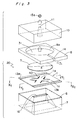
- Fig. 3 shows the ink jet head in an exploded state as viewed obliquely.
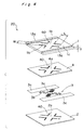
- Fig. 4 shows the buckling member 1 as well as the first insulating film 2, the heater layer 3, and the second insulating film 4 present in the rear of the buckling member 1 (omitted in Fig. 3).
- the substrate 7, the buckling member 1, and the first insulating film 2 and second insulating film 4 are represented each in a rectangular form in Figs. 3 and 4, they may actually be extended peripherally (except the areas of the electrode pads 13a, 13b).
- the substrate 7 is formed of a silicon (Si) plate having a silicon oxide film, which is formed by thermal oxidation in this case, as the surface protective film 6.
- the thermal conductivity of the substrate 7 is around 70 W ⁇ m -1 ⁇ K -1 .
- the film thickness of the surface protective film 6 is desirably thicker to ensure the insulating property, but desirably thinner for thermal conduction. As a conclusion, the film thickness of the surface protective film 6 is set within a range of 0.5 to 1 ⁇ m.
- a refrigerant circulation hole 16 is bored generally in the center of the substrate 7.
- the refrigerant circulation hole 16 is a hole bored through the substrate 7 and having a rectangular cross section, where the dimensions of the sides of the rectangular shape of the refrigerant circulation hole 16 (dimensions in cross section) are so set as to gradually decrease from the rear toward the front side of the substrate 7.
- This setting is intended to minimize the loss of the area at which the pressure generating member 20 is, or especially the buckling member 1 and the heater layer 3 are, opposed to the front surface of the substrate 7.
- the pressure generating member 20 and the substrate 7 are opposed to each other over a large area, so that heat of the pressure generating member 20, especially of the buckling member 1 and the heater layer 3, can be discharged out of the ink chamber through the substrate 7 with high efficiency in operation.
- the buckling member 1 is made of a metal material (whose thickness is assumed to be "t") such as nickel.
- the buckling member 1 is formed into a two-layer structure in which 0.01 ⁇ m thick tantalum with a small linear coefficient of expansion is disposed on the substrate 7 side while 6 ⁇ m thick nickel with a large lineal coefficient of expansion is disposed on the nozzle plate 10 side, in order that the buckling member 1, when buckling due to thermal expansion, will be deformed toward the nozzle plate 10 side.
- the first insulating film 2 and the second insulating film 4 are made of an insulating material such as silicon oxide or alumina.
- the first insulating film 2 and the second insulating film 4 prevent the current flowing through the heater layer 3 from leaking into the substrate 7 or the buckling member 1. Thus, the power consumption can be reduced.
- the buckling member 1, the first insulating film 2, and the second insulating film 4 have four L-shaped slits 40 bored through their rectangular planes.
- the four slits 40 are arranged so as to be separated from one another with the bent portion of the L pointed to the center.
- cross-shaped portions 2a, 4a, and 1a are formed in center portions of the first insulating film 2, the second insulating film 4, and the buckling member 1, respectively.
- terminal ends of the side lines 1b (length L, width W) of the cross-shaped portion 1a of the buckling member 1 are supported by a peripheral portion 1c of the buckling member 1, so that the buckling member 1 is actually buckled when the side lines 1b of the cross-shaped portion 1a are heated.
- thermal stress of the buckling portions 1b due to repeated heating and cooling processes can be received by the whole peripheral portion 1c. That is, the thermal stress of the side lines 1b of the cross-shaped portion 1a is generated outward in their longitudinal direction.
- the heater layer 3 is made from, for example, nickel or nickel chromium alloy or other like materials.
- the heater layer 3 has strip-shaped electrode portions 3c, 3c extending in parallel around the first and second insulating films 2, 4; a circular portion 3a sandwiched by the center portions (crossing portions of the side lines 1b) of the cross-shaped portions 2a, 4a of the first and second insulating films 2, 4; and a strip-shaped resistance portion 3b which is sandwiched by the side lines 1b of the cross-shaped portions 2a, 4a of the first and second insulating films 2, 4 and which is meandered in U-shape to connect the electrode portions 3c, 3c and the circular portion 3a with each other.
- the electrode pads 13a, 13b made of the same layer as the buckling member 1 are connected onto the electrode portions 3c, 3c.
- the heater layer 3 can be formed into a narrow pattern irrespectively of the shape of the buckling member 1. Therefore, the amount of electrical energization required for necessary quantity of heat generation can be reduced so that the power consumption can be reduced.
- the diaphragm 5 is made of an elastic material such as nickel and formed into a generally disc shape (with diameter E). Thanks to this diaphragm 5, ink 15 present in a clearance 31 between the nozzle plate 10 and the pressure generating member 20 as shown in Fig. 1 can be prevented from going around to the rear side of the pressure generating member 20 during an operation. Accordingly, the discharge force and discharge velocity of ink can be increased and, as a result, practical operating characteristics can be obtained. In particular, since this diaphragm 5 is formed into a generally disc shape, the volumetric variation of the ink chamber (clearance) 31 is large for a small surface area of the diaphragm 5.
- the spacer 8 is made of an insulating film material such as polyimide or acrylic photosensitive adhesives having a specified thickness.
- This spacer 8 has a through hole 8a drilled into a circular shape in order to form the clearance 31 in which ink should be filled between the diaphragm 5 and the nozzle plate 10.
- an ink feed passage 14 which passes through the spacer insulating film in its thickness direction with a specified width and which leads from the film end portion into the through hole 8a.
- the nozzle plate 10 is made of, for example, a 0.2 mm thick glass or plastic sheet material.
- a nozzle orifice 11 as a nozzle opening is formed generally in the center of the nozzle plate 10.
- This nozzle orifice 11 is a hole having a circular-shaped cross section and bored through the nozzle plate 10, and the inner diameter of the nozzle orifice 11 is so set as to gradually decrease from the rear toward the front side of the nozzle plate 10.
- the first insulating film 2, the heater layer 3, the second insulating film 4, and the buckling member 1 are in entire, close contact with one another. They are fitted on the substrate 7 (including the surface protective film 6) side in such a way that only their peripheral portions (Fig. 1 depicts only the portions that form both ends of the peripheral portion in one direction) are bent and mounted and supported by the substrate 7. Portions of the first insulating film 2, the heater layer 3, the second insulating film 4, and the buckling member 1 inner than the aforementioned peripheral portions are separate from the substrate 7, and a clearance 32 is formed between the surface protective film 6 of the substrate 7 and the portion of the first insulating film 2 inner than the aforementioned peripheral portion.
- This clearance 32 communicates with the refrigerant reservoir 34 through the refrigerant circulation hole 16.
- the electrode pads 13a, 13b are located outside the spacer 8, or outside the ink chamber.
- the electrode pad 13a is connected to a switch 52 via a wiring 51a. This switch is so arranged as to perform switching between power supply 12 and ground.
- the electrode pad 13b is connected to the ground via a wiring 51b.
- a center portion 5a and a peripheral portion 5c of the diaphragm 5 are protruded or bent toward the buckling member 1, and the center portion 5a is fitted to and supported by the center portion 1a of the buckling member 1. Also, the peripheral portion 5c of the diaphragm 5 is fitted to the peripheral portion 1c of the buckling member 1, and therefore fitted to and supported by the substrate 7 together with the peripheral portions of the first insulating film 2, the heater layer 3, the second insulating film 4, and the buckling member 1.
- An intermediate portion 5b of the diaphragm 5 (a portion between the center portion 5a and the peripheral portion 5c) is separate from the buckling member 1, so that a clearance 33 is formed between the buckling member 1 and the intermediate portion 5b of the diaphragm 5.
- This clearance 33 communicates with the clearance 32 between the surface protective film 6 of the substrate 7 and the first insulating film 2 through the slits 40 shown in Fig. 4, and further communicates with the refrigerant reservoir 34 through the refrigerant circulation hole 16.
- the buckling member 1 and the diaphragm 5, which constitute the pressure generating member 20 are formed separately, the shape of the buckling member 1 and that of the diaphragm 5 may be freely designed with almost no restrictions by each other.
- the ink feed passage 14 leading to the ink chamber (clearance) 31 and a refrigerant feed passage 35 leading to the refrigerant reservoir 34 are branched from unshown one ink feed passage. Therefore, the ink 15 fed to the ink chamber 31 is also fed to the refrigerant reservoir 34 as a refrigerant.
- the thermal conductivity of the ink 15 is a common one around 0.5 W ⁇ m -1 ⁇ K -1 .
- the present ink jet head is driven in steps as follows:
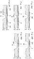
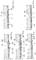
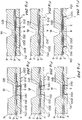
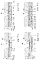
- Figs. 15A, 15B, 16A, 16B, ..., 31A, and 31B show the processes of fabricating the pressure generating member 20, which is a main part of the ink jet head 90.
- a group of Figs. 15A, 16A, 17A, 18A, 19A, 20, 21A, 23A, 24A, 25A, 26A, 27A, 30A, and 31A, and another group of Figs. 15B, 16B, 17B, 18B, 19B, 21B, 22, 23B, 24B, 25B, 26B, 27B, 28B, 29, 30B, and 31B correspond to the cross section taken along the line X1 - X1 and that taken along the line Y1 - Y1 in Fig. 3, respectively.
- the ink jet head 90 can be fabricated into small size. Also, since the two clearances 32, 33 in the pressure generating member 20 are formed collectively and continuously, the fabricating process can be simplified. Yet, since the clearances 32, 33 are formed according to the thicknesses of the first sacrifice layer 120 and the second sacrifice layer 210, the dimension of the clearances 32, 33, or the interval A between the surface protective film 6 of the substrate 7 and the first insulating film 2, as well as the interval D between the buckling member 1 and the diaphragm 5 can be set each with a high accuracy. For example, the interval A can be set to 0.1 ⁇ m or less and the interval D can be set to 1.0 ⁇ m or more. As a result, the response speed of the ink jet head 90 can be improved so that high-speed printing can be realized.
- the substrate is present on the rear side, heat of the pressure generating member, especially of the buckling member and the heater layer, can be discharged out of the ink chamber rapidly through the substrate, by selecting a material having a thermal conductivity larger than that of ink by one order or more as the material of the substrate. Accordingly, the cooling rate of the pressure generating member can be made high and, as a result, a good response characteristic is obtained so that high-speed printing becomes possible.
- the buckling member and the heater layer, which constitute the pressure generating member are provided by independent layers, the heater layer may be shaped into a narrow pattern irrespectively of the shape of the buckling member. Such an arrangement saves the amount of current for energization involved in obtaining a required amount of heat so that the power consumption can be reduced.
- the substrate is present on the rear side of the pressure generating member, heat of the pressure generating member, especially of the buckling member, can be discharged out of the ink chamber rapidly through the substrate, by selecting a material having a thermal conductivity larger than that of ink by one order or more as the material of the substrate. Accordingly, the cooling rate of the pressure generating member can be made high and, as a result, a good response characteristic is obtained so that high-speed printing becomes possible. Also, thanks to the diaphragm, the ink present in a clearance between the nozzle plate and the pressure generating member (diaphragm) can be prevented from going around to the rear side of the pressure generating member (diaphragm) during an operation.
- the discharge force and discharge rate of ink can be made large.
- the buckling member and the diaphragm, which constitute the pressure generating member are provided separately, the buckling member may be shaped irrespectively of the shape of the diaphragm. For example, it becomes possible to form slits in the buckling member. Such an arrangement allows the buckling member to be rapidly cooled by circulating the refrigerant such as ink through the buckling member on the rear side of the diaphragm. As a result, an even better response characteristic can be obtained so that high-speed printing becomes possible.
- the substrate is present on the rear side of the pressure generating member, heat of the pressure generating member, especially of the buckling member and the heater layer, can be discharged out of the ink chamber rapidly through the substrate, by selecting a material having a thermal conductivity larger than that of ink by one order or more as the material of the substrate. Accordingly, the cooling rate of the pressure generating member can be made high and, as a result, a good response characteristic can be obtained so that high-speed printing becomes possible. Also, since the buckling member and the heater layer, which constitute the pressure generating member, are provided by independent layers, the heater layer may be shaped into a narrow pattern irrespectively of the shape of the buckling member.
- the buckling member and the diaphragm which constitute the pressure generating member, are provided separately, the buckling member may be shaped irrespectively of the shape of the diaphragm. For example, it becomes possible to form slits in the buckling member.
- Such an arrangement allows the buckling member and the heater layer to be rapidly cooled by circulating the refrigerant such as ink through the buckling member on the rear side of the diaphragm. As a result, an even better response characteristic can be obtained so that high-speed printing becomes possible.
- the heater layer is provided along the rear surface of the buckling member out of both surfaces of the buckling member, the heater layer that has been heated to a high temperature particularly out of the pressure generating member can be rapidly cooled through the substrate. Accordingly, the cooling rate of the pressure generating member can be made even higher and, as a result, an even better response characteristic can be obtained so that high-speed printing becomes possible.
- the pressure generating member since the pressure generating member has a first insulating layer provided between the substrate and the heater layer, the substrate and the heater layer can be successfully insulated from each other so that the current flowing through the heater layer can be prevented from leaking to the substrate. As a result, the amount of current required to obtain the necessary heat generation can be saved so that the power consumption can be reduced.
- the pressure generating member since the pressure generating member has a second insulating layer provided between the buckling member and the heater layer, the buckling member and the heater layer can be successfully insulated from each other so that the current flowing through the heater layer can be prevented from leaking to the buckling member. As a result, the amount or current required to obtain the necessary heat generation can be saved so that the power consumption can be reduced.
- the diaphragm is formed into a generally disc shape, the volumetric variation of the ink chamber (a clearance between the nozzle plate and the pressure generating member) can be made large for a small surface area of the diaphragm. Accordingly, the discharge force and discharge rate can be made large for the small surface area of the diaphragm. Conversely, when the discharge force of ink is larger than necessary, the ink jet head may be miniaturized by reducing the diameter of the diaphragm.
- the diaphragm other than the peripheral portion is coupled to the buckling member. Therefore, when the buckling member is going to restore to the original position after a heating period and upon the entrance into a cooling period, the diaphragm undergoes a tensile force from the buckling member in addition to its own restoring force. As a result of this, the diaphragm restores to the original position faster. Accordingly, the response characteristic of the pressure generating member can be improved so that high-speed printing is enabled.
- the center portion of the diaphragm is coupled to the center portion of the buckling member. Therefore, a portion (center portion) that has been displaced to the most extent out of the diaphragm during a heating period is pulled by a portion (center portion) that restores fastest out of the buckling member upon the entrance into a cooling period. As a result, the diaphragm restores to the original position even faster. Accordingly, the response characteristic of the pressure generating member can be improved so that high-speed printing is enabled.
- a clearance is provided between an intermediate portion between the peripheral portion and the part coupled to the buckling member out of the diaphragm, and the buckling member. Therefore, it becomes possible to rapidly cool the buckling member by circulating the refrigerant such as ink through the clearance between the diaphragm and the buckling member, on the rear side of the diaphragm. As a result, an even better response characteristic can be obtained so that high-speed printing is enabled.
- a clearance is provided between a portion of the buckling member inner than its peripheral portion out of the pressure generating member, and the substrate. Therefore, it becomes possible to rapidly cool the buckling member and the heater layer by circulating the refrigerant such as ink through the clearance between the buckling ember and the substrate, on the rear side of the diaphragm. As a result, an even better response characteristic can be obtained so that high-speed printing is enabled.
- the distance between the substrate and the aforementioned portion of the pressure generating member is set to within a range of 0.05 ⁇ m to 2.0 ⁇ m. Therefore, the clearance between the substrate and the pressure generating member can be easily formed, and also the response characteristic of the pressure generating member can be maintained good. That is, if the dimension of the clearance is 0.05 ⁇ m or more, the clearance can be formed by stacking the material of the sacrifice layer (a layer for processing) and that of the pressure generating member on the substrate one by one, and by removing the sacrifice layer with an etchant. Further, if the dimension of the clearance is 2.0 ⁇ m or less, heat of the pressure generating member, especially of the buckling member and the heater layer, can be discharged rapidly out of the ink chamber through the substrate during a cooling period.
- a slit is provided at a portion of the pressure generating member inner than the peripheral portion of the buckling member, so as to be bored through from the surface opposite to the substrate to the diaphragm side surface of the buckling member. Therefore, the buckling member can be rapidly cooled by circulating the refrigerant such as ink through the slit on the rear side of the diaphragm.
- these clearances communicate with each other through the slit so that the cooling effect can be enhanced.
- the response characteristic is further improved so that high-speed printing is enabled.
- a plurality of slits as described above are provided, and it is arranged that a strip-shaped portion of the buckling member sandwiched by the slits will be buckled. Therefore, for example, by attaching the entire peripheral portion of the buckling member to the substrate, thermal stress of the buckling portion due to repeated heating and cooling can be received by the entire peripheral portion. Accordingly, the thermal stress of the buckling portion is not applied only to particular portions, but can be relaxed and received by the entire peripheral portion. As a result, the place where the substrate and the buckling member are fitted to each other can be prevented from being damaged, so that the ink jet head can be prolonged in its service life.
- the substrate is provided with a refrigerant circulation hole which is bored through the substrate and which confronts a portion of the pressure generating member inner than the peripheral portion of the buckling member. Therefore, the refrigerant such as ink can be fed from the rear side of the substrate to the front side of the substrate through the refrigerant circulation hole.
- the fed refrigerant circulates between the front and rear sides of the substrate as the pressure generating member is displaced and restored by heating and cooling. Accordingly, it becomes possible to rapidly cool the pressure generating member. This fact is particularly significant when the ink is prevented from going around to the rear side of the diaphragm by the diaphragm being provided.
- the refrigerant circulates through the clearances or slits so that the cooling effect can be enhanced. As a result, an even better response characteristic can be obtained so that high-speed printing is enabled.
- the refrigerant circulation hole is so arranged that its size gradually decreases from the rear side toward the front side of the substrate. Therefore, the opposing area between the pressure generating member and the substrate surface is less reduced as compared to when the refrigerant circulation hole is not provided. Accordingly, heat of the pressure generating member, especially heat of the buckling member and the heater layer, can be discharged rapidly out of the ink chamber through the substrate. As a result, the cooling rate of the pressure generating member can be maintained high, so that the response characteristic can be maintained good.
- a refrigerant reservoir communicating with the refrigerant circulation hole is formed on the rear side of the substrate. Therefore, the refrigerant such as ink can be fed to the front side of the substrate from the refrigerant reservoir through the refrigerant circulation hole.
- the ink jet head since the pressure generating member can be fabricated by semiconductor integrating processes, the ink jet head can be fabricated into small size. Further, two clearances, i.e., one clearance between the substrate and the pressure generating member and the other clearance between the buckling member and the diaphragm in the pressure generating member, can be collectively fabricated by etching and removing continuously the first sacrifice layer and the second sacrifice layer. Accordingly, the fabrication processes can be simplified. Yet, the two clearances are formed in response to the thicknesses of the first sacrifice layer and the second sacrifice layer, respectively, so that the distances of the clearances can be set with high accuracy.
Landscapes
- Particle Formation And Scattering Control In Inkjet Printers (AREA)
- Accessory Devices And Overall Control Thereof (AREA)
Applications Claiming Priority (2)
| Application Number | Priority Date | Filing Date | Title |
|---|---|---|---|
| JP6290123A JPH08142323A (ja) | 1994-11-24 | 1994-11-24 | インクジェットヘッドおよびその製造方法 |
| JP290123/94 | 1994-11-24 |
Publications (2)
| Publication Number | Publication Date |
|---|---|
| EP0713774A2 true EP0713774A2 (fr) | 1996-05-29 |
| EP0713774A3 EP0713774A3 (fr) | 1997-04-02 |
Family
ID=17752106
Family Applications (1)
| Application Number | Title | Priority Date | Filing Date |
|---|---|---|---|
| EP95108400A Withdrawn EP0713774A3 (fr) | 1994-11-24 | 1995-05-31 | Tête d'impression à jet d'encre pour impression à grande vitesse et procédé pour sa fabrication |
Country Status (2)
| Country | Link |
|---|---|
| EP (1) | EP0713774A3 (fr) |
| JP (1) | JPH08142323A (fr) |
Cited By (79)
| Publication number | Priority date | Publication date | Assignee | Title |
|---|---|---|---|---|
| EP0816083A3 (fr) * | 1996-06-27 | 1998-09-16 | Samsung Electronics Co., Ltd. | Dispositif et procédé de pulvérisation d'encre |
| WO1999003681A1 (fr) * | 1997-07-15 | 1999-01-28 | Silverbrook Research Pty. Limited | Jet d'encre a commande thermique |
| US5929877A (en) * | 1995-06-19 | 1999-07-27 | Franoctyp-Postalia Ag & Co. | Method and arrangement for maintaining the nozzles of an ink print head clean by forming a solvent-enriched microclimate in an antechamber containing the nozzles |
| EP0931654A1 (fr) * | 1998-01-23 | 1999-07-28 | Océ-Technologies B.V. | Tête à buse à jet d'encre |
| US6213589B1 (en) | 1997-07-15 | 2001-04-10 | Silverbrook Research Pty Ltd. | Planar thermoelastic bend actuator ink jet printing mechanism |
| US6239821B1 (en) | 1997-07-15 | 2001-05-29 | Silverbrook Research Pty Ltd | Direct firing thermal bend actuator ink jet printing mechanism |
| US6280022B1 (en) | 1998-01-23 | 2001-08-28 | Oce-Technologies B.V. | Ink jet nozzle head |
| WO2002016140A1 (fr) * | 2000-08-23 | 2002-02-28 | Olivetti Tecnost S.P.A. | Tete d'impression monolithique a cannelures autoalignees et procede de fabrication associe |
| US6390603B1 (en) | 1997-07-15 | 2002-05-21 | Silverbrook Research Pty Ltd | Buckle plate ink jet printing mechanism |
| US6640402B1 (en) | 1998-04-30 | 2003-11-04 | Hewlett-Packard Development Company, L.P. | Method of manufacturing an ink actuator |
| US6746105B2 (en) | 1997-07-15 | 2004-06-08 | Silverbrook Research Pty. Ltd. | Thermally actuated ink jet printing mechanism having a series of thermal actuator units |
| US6776476B2 (en) | 1997-07-15 | 2004-08-17 | Silverbrook Research Pty Ltd. | Ink jet printhead chip with active and passive nozzle chamber structures |
| US6783217B2 (en) | 1997-07-15 | 2004-08-31 | Silverbrook Research Pty Ltd | Micro-electromechanical valve assembly |
| US6786661B2 (en) | 1997-07-15 | 2004-09-07 | Silverbrook Research Pty Ltd. | Keyboard that incorporates a printing mechanism |
| US6786570B2 (en) | 1997-07-15 | 2004-09-07 | Silverbrook Research Pty Ltd | Ink supply arrangement for a printing mechanism of a wide format pagewidth inkjet printer |
| US6824251B2 (en) | 1997-07-15 | 2004-11-30 | Silverbrook Research Pty Ltd | Micro-electromechanical assembly that incorporates a covering formation for a micro-electromechanical device |
| US6834939B2 (en) | 2002-11-23 | 2004-12-28 | Silverbrook Research Pty Ltd | Micro-electromechanical device that incorporates covering formations for actuators of the device |
| US6880918B2 (en) | 1997-07-15 | 2005-04-19 | Silverbrook Research Pty Ltd | Micro-electromechanical device that incorporates a motion-transmitting structure |
| US6880914B2 (en) | 1997-07-15 | 2005-04-19 | Silverbrook Research Pty Ltd | Inkjet pagewidth printer for high volume pagewidth printing |
| US6886917B2 (en) | 1998-06-09 | 2005-05-03 | Silverbrook Research Pty Ltd | Inkjet printhead nozzle with ribbed wall actuator |
| US6886918B2 (en) | 1998-06-09 | 2005-05-03 | Silverbrook Research Pty Ltd | Ink jet printhead with moveable ejection nozzles |
| US6916082B2 (en) | 1997-07-15 | 2005-07-12 | Silverbrook Research Pty Ltd | Printing mechanism for a wide format pagewidth inkjet printer |
| US6927786B2 (en) | 1997-07-15 | 2005-08-09 | Silverbrook Research Pty Ltd | Ink jet nozzle with thermally operable linear expansion actuation mechanism |
| US6929352B2 (en) | 1997-07-15 | 2005-08-16 | Silverbrook Research Pty Ltd | Inkjet printhead chip for use with a pulsating pressure ink supply |
| US6932459B2 (en) | 1997-07-15 | 2005-08-23 | Silverbrook Research Pty Ltd | Ink jet printhead |
| US6935724B2 (en) | 1997-07-15 | 2005-08-30 | Silverbrook Research Pty Ltd | Ink jet nozzle having actuator with anchor positioned between nozzle chamber and actuator connection point |
| US6934969B2 (en) | 2002-12-27 | 2005-08-30 | Kimberly-Clark Worldwide, Inc. | Anti-wicking protective workwear and methods of making and using same |
| AU2002325589B2 (en) * | 1997-07-15 | 2005-09-08 | Memjet Technology Limited | A thermally actuated ink jet |
| US6957884B2 (en) | 2002-12-27 | 2005-10-25 | Kinberly-Clark Worldwide, Inc. | High-speed inkjet printing for vibrant and crockfast graphics on web materials or end-products |
| US6976751B2 (en) | 1997-07-15 | 2005-12-20 | Silverbrook Research Pty Ltd | Motion transmitting structure |
| US6986613B2 (en) | 1997-07-15 | 2006-01-17 | Silverbrook Research Pty Ltd | Keyboard |
| US7004566B2 (en) | 1997-07-15 | 2006-02-28 | Silverbrook Research Pty Ltd | Inkjet printhead chip that incorporates micro-mechanical lever mechanisms |
| US7008041B2 (en) | 1997-07-15 | 2006-03-07 | Silverbrook Research Pty Ltd | Printing mechanism having elongate modular structure |
| US7008046B2 (en) | 1997-07-15 | 2006-03-07 | Silverbrook Research Pty Ltd | Micro-electromechanical liquid ejection device |
| US7022250B2 (en) | 1997-07-15 | 2006-04-04 | Silverbrook Research Pty Ltd | Method of fabricating an ink jet printhead chip with differential expansion actuators |
| US7040738B2 (en) | 1997-07-15 | 2006-05-09 | Silverbrook Research Pty Ltd | Printhead chip that incorporates micro-mechanical translating mechanisms |
| US7044584B2 (en) | 1997-07-15 | 2006-05-16 | Silverbrook Research Pty Ltd | Wide format pagewidth inkjet printer |
| US7066574B2 (en) | 1997-07-15 | 2006-06-27 | Silverbrook Research Pty Ltd | Micro-electromechanical device having a laminated thermal bend actuator |
| US7111924B2 (en) | 1998-10-16 | 2006-09-26 | Silverbrook Research Pty Ltd | Inkjet printhead having thermal bend actuator heating element electrically isolated from nozzle chamber ink |
| US7131715B2 (en) | 1997-07-15 | 2006-11-07 | Silverbrook Research Pty Ltd | Printhead chip that incorporates micro-mechanical lever mechanisms |
| US7144519B2 (en) | 1998-10-16 | 2006-12-05 | Silverbrook Research Pty Ltd | Method of fabricating an inkjet printhead chip having laminated actuators |
| US7147302B2 (en) | 1997-07-15 | 2006-12-12 | Silverbrook Researh Pty Ltd | Nozzle assembly |
| US7147305B2 (en) | 1997-07-15 | 2006-12-12 | Silverbrook Research Pty Ltd | Printer formed from integrated circuit printhead |
| US7155746B2 (en) | 2002-12-27 | 2007-01-02 | Kimberly-Clark Worldwide, Inc. | Anti-wicking protective workwear and methods of making and using same |
| US7175260B2 (en) | 2002-06-28 | 2007-02-13 | Silverbrook Research Pty Ltd | Ink jet nozzle arrangement configuration |
| US7195339B2 (en) | 1997-07-15 | 2007-03-27 | Silverbrook Research Pty Ltd | Ink jet nozzle assembly with a thermal bend actuator |
| US7207654B2 (en) | 1997-07-15 | 2007-04-24 | Silverbrook Research Pty Ltd | Ink jet with narrow chamber |
| CN1319740C (zh) * | 1999-06-30 | 2007-06-06 | 西尔弗布鲁克研究股份有限公司 | 在微型机电器件内检测故障和排除故障的方法 |
| US7240992B2 (en) | 1997-07-15 | 2007-07-10 | Silverbrook Research Pty Ltd | Ink jet printhead incorporating a plurality of nozzle arrangement having backflow prevention mechanisms |
| US7246884B2 (en) | 1997-07-15 | 2007-07-24 | Silverbrook Research Pty Ltd | Inkjet printhead having enclosed inkjet actuators |
| US7246883B2 (en) | 1997-07-15 | 2007-07-24 | Silverbrook Research Pty Ltd | Motion transmitting structure for a nozzle arrangement of a printhead chip for an inkjet printhead |
| US7252366B2 (en) | 1997-07-15 | 2007-08-07 | Silverbrook Research Pty Ltd | Inkjet printhead with high nozzle area density |
| US7267424B2 (en) | 1997-07-15 | 2007-09-11 | Silverbrook Research Pty Ltd | Wide format pagewidth printer |
| US7278711B2 (en) | 1997-07-15 | 2007-10-09 | Silverbrook Research Pty Ltd | Nozzle arrangement incorporating a lever based ink displacement mechanism |
| US7287836B2 (en) | 1997-07-15 | 2007-10-30 | Sil;Verbrook Research Pty Ltd | Ink jet printhead with circular cross section chamber |
| US7303254B2 (en) | 1997-07-15 | 2007-12-04 | Silverbrook Research Pty Ltd | Print assembly for a wide format pagewidth printer |
| US7334873B2 (en) | 2002-04-12 | 2008-02-26 | Silverbrook Research Pty Ltd | Discrete air and nozzle chambers in a printhead chip for an inkjet printhead |
| US7360872B2 (en) | 1997-07-15 | 2008-04-22 | Silverbrook Research Pty Ltd | Inkjet printhead chip with nozzle assemblies incorporating fluidic seals |
| US7381340B2 (en) | 1997-07-15 | 2008-06-03 | Silverbrook Research Pty Ltd | Ink jet printhead that incorporates an etch stop layer |
| US7401901B2 (en) | 1997-07-15 | 2008-07-22 | Silverbrook Research Pty Ltd | Inkjet printhead having nozzle plate supported by encapsulated photoresist |
| US7407269B2 (en) | 2002-06-28 | 2008-08-05 | Silverbrook Research Pty Ltd | Ink jet nozzle assembly including displaceable ink pusher |
| US7431446B2 (en) | 1997-07-15 | 2008-10-07 | Silverbrook Research Pty Ltd | Web printing system having media cartridge carousel |
| US7434915B2 (en) | 1997-07-15 | 2008-10-14 | Silverbrook Research Pty Ltd | Inkjet printhead chip with a side-by-side nozzle arrangement layout |
| US7461924B2 (en) | 1997-07-15 | 2008-12-09 | Silverbrook Research Pty Ltd | Printhead having inkjet actuators with contractible chambers |
| US7465030B2 (en) | 1997-07-15 | 2008-12-16 | Silverbrook Research Pty Ltd | Nozzle arrangement with a magnetic field generator |
| US7468139B2 (en) | 1997-07-15 | 2008-12-23 | Silverbrook Research Pty Ltd | Method of depositing heater material over a photoresist scaffold |
| US7524026B2 (en) | 1997-07-15 | 2009-04-28 | Silverbrook Research Pty Ltd | Nozzle assembly with heat deflected actuator |
| US7556356B1 (en) | 1997-07-15 | 2009-07-07 | Silverbrook Research Pty Ltd | Inkjet printhead integrated circuit with ink spread prevention |
| US7571988B2 (en) | 2000-05-23 | 2009-08-11 | Silverbrook Research Pty Ltd | Variable-volume nozzle arrangement |
| US7607756B2 (en) | 1997-07-15 | 2009-10-27 | Silverbrook Research Pty Ltd | Printhead assembly for a wallpaper printer |
| US7753463B2 (en) | 1997-07-15 | 2010-07-13 | Silverbrook Research Pty Ltd | Processing of images for high volume pagewidth printing |
| US7758142B2 (en) | 2002-04-12 | 2010-07-20 | Silverbrook Research Pty Ltd | High volume pagewidth printing |
| US7784902B2 (en) | 1997-07-15 | 2010-08-31 | Silverbrook Research Pty Ltd | Printhead integrated circuit with more than 10000 nozzles |
| US7802871B2 (en) | 1997-07-15 | 2010-09-28 | Silverbrook Research Pty Ltd | Ink jet printhead with amorphous ceramic chamber |
| US7854500B2 (en) | 1998-11-09 | 2010-12-21 | Silverbrook Research Pty Ltd | Tamper proof print cartridge for a video game console |
| US7891767B2 (en) | 1997-07-15 | 2011-02-22 | Silverbrook Research Pty Ltd | Modular self-capping wide format print assembly |
| US7967418B2 (en) | 1997-07-15 | 2011-06-28 | Silverbrook Research Pty Ltd | Printhead with nozzles having individual supply passages extending into substrate |
| US8029101B2 (en) | 1997-07-15 | 2011-10-04 | Silverbrook Research Pty Ltd | Ink ejection mechanism with thermal actuator coil |
| US8109611B2 (en) | 2002-04-26 | 2012-02-07 | Silverbrook Research Pty Ltd | Translation to rotation conversion in an inkjet printhead |
Families Citing this family (2)
| Publication number | Priority date | Publication date | Assignee | Title |
|---|---|---|---|---|
| US7943813B2 (en) | 2002-12-30 | 2011-05-17 | Kimberly-Clark Worldwide, Inc. | Absorbent products with enhanced rewet, intake, and stain masking performance |
| JP5073594B2 (ja) * | 2007-09-04 | 2012-11-14 | 株式会社リコー | 液体吐出ヘッドユニット及び画像形成装置 |
Citations (1)
| Publication number | Priority date | Publication date | Assignee | Title |
|---|---|---|---|---|
| JPH0230543A (ja) | 1988-07-21 | 1990-01-31 | Seiko Epson Corp | インクジェットヘッド |
Family Cites Families (1)
| Publication number | Priority date | Publication date | Assignee | Title |
|---|---|---|---|---|
| GB2286157B (en) * | 1994-01-31 | 1998-01-14 | Neopost Ltd | Ink jet printing device |
-
1994
- 1994-11-24 JP JP6290123A patent/JPH08142323A/ja active Pending
-
1995
- 1995-05-31 EP EP95108400A patent/EP0713774A3/fr not_active Withdrawn
Patent Citations (1)
| Publication number | Priority date | Publication date | Assignee | Title |
|---|---|---|---|---|
| JPH0230543A (ja) | 1988-07-21 | 1990-01-31 | Seiko Epson Corp | インクジェットヘッド |
Cited By (269)
| Publication number | Priority date | Publication date | Assignee | Title |
|---|---|---|---|---|
| US5929877A (en) * | 1995-06-19 | 1999-07-27 | Franoctyp-Postalia Ag & Co. | Method and arrangement for maintaining the nozzles of an ink print head clean by forming a solvent-enriched microclimate in an antechamber containing the nozzles |
| EP0816083A3 (fr) * | 1996-06-27 | 1998-09-16 | Samsung Electronics Co., Ltd. | Dispositif et procédé de pulvérisation d'encre |
| US7325918B2 (en) | 1997-07-15 | 2008-02-05 | Silverbrook Research Pty Ltd | Print media transport assembly |
| US7083261B2 (en) | 1997-07-15 | 2006-08-01 | Silverbrook Research Pty Ltd | Printer incorporating a microelectromechanical printhead |
| US6213589B1 (en) | 1997-07-15 | 2001-04-10 | Silverbrook Research Pty Ltd. | Planar thermoelastic bend actuator ink jet printing mechanism |
| US6239821B1 (en) | 1997-07-15 | 2001-05-29 | Silverbrook Research Pty Ltd | Direct firing thermal bend actuator ink jet printing mechanism |
| US8419165B2 (en) | 1997-07-15 | 2013-04-16 | Zamtec Ltd | Printhead module for wide format pagewidth inkjet printer |
| US8408679B2 (en) | 1997-07-15 | 2013-04-02 | Zamtec Ltd | Printhead having CMOS drive circuitry |
| US6390603B1 (en) | 1997-07-15 | 2002-05-21 | Silverbrook Research Pty Ltd | Buckle plate ink jet printing mechanism |
| US8287105B2 (en) | 1997-07-15 | 2012-10-16 | Zamtec Limited | Nozzle arrangement for an inkjet printhead having an ink ejecting roof structure |
| US6746105B2 (en) | 1997-07-15 | 2004-06-08 | Silverbrook Research Pty. Ltd. | Thermally actuated ink jet printing mechanism having a series of thermal actuator units |
| US6776476B2 (en) | 1997-07-15 | 2004-08-17 | Silverbrook Research Pty Ltd. | Ink jet printhead chip with active and passive nozzle chamber structures |
| US6783217B2 (en) | 1997-07-15 | 2004-08-31 | Silverbrook Research Pty Ltd | Micro-electromechanical valve assembly |
| US6786661B2 (en) | 1997-07-15 | 2004-09-07 | Silverbrook Research Pty Ltd. | Keyboard that incorporates a printing mechanism |
| US6786570B2 (en) | 1997-07-15 | 2004-09-07 | Silverbrook Research Pty Ltd | Ink supply arrangement for a printing mechanism of a wide format pagewidth inkjet printer |
| US6808325B2 (en) | 1997-07-15 | 2004-10-26 | Silverbrook Research Pty Ltd | Keyboard with an internal printer |
| US6824251B2 (en) | 1997-07-15 | 2004-11-30 | Silverbrook Research Pty Ltd | Micro-electromechanical assembly that incorporates a covering formation for a micro-electromechanical device |
| US8123336B2 (en) | 1997-07-15 | 2012-02-28 | Silverbrook Research Pty Ltd | Printhead micro-electromechanical nozzle arrangement with motion-transmitting structure |
| US6840600B2 (en) | 1997-07-15 | 2005-01-11 | Silverbrook Research Pty Ltd | Fluid ejection device that incorporates covering formations for actuators of the fluid ejection device |
| US6848780B2 (en) | 1997-07-15 | 2005-02-01 | Sivlerbrook Research Pty Ltd | Printing mechanism for a wide format pagewidth inkjet printer |
| US6880918B2 (en) | 1997-07-15 | 2005-04-19 | Silverbrook Research Pty Ltd | Micro-electromechanical device that incorporates a motion-transmitting structure |
| US6880914B2 (en) | 1997-07-15 | 2005-04-19 | Silverbrook Research Pty Ltd | Inkjet pagewidth printer for high volume pagewidth printing |
| US8113629B2 (en) | 1997-07-15 | 2012-02-14 | Silverbrook Research Pty Ltd. | Inkjet printhead integrated circuit incorporating fulcrum assisted ink ejection actuator |
| US8083326B2 (en) | 1997-07-15 | 2011-12-27 | Silverbrook Research Pty Ltd | Nozzle arrangement with an actuator having iris vanes |
| US8075104B2 (en) | 1997-07-15 | 2011-12-13 | Sliverbrook Research Pty Ltd | Printhead nozzle having heater of higher resistance than contacts |
| US6916082B2 (en) | 1997-07-15 | 2005-07-12 | Silverbrook Research Pty Ltd | Printing mechanism for a wide format pagewidth inkjet printer |
| US6918707B2 (en) | 1997-07-15 | 2005-07-19 | Silverbrook Research Pty Ltd | Keyboard printer print media transport assembly |
| US6921221B2 (en) | 1997-07-15 | 2005-07-26 | Silverbrook Research Pty Ltd | Combination keyboard and printer apparatus |
| US6923583B2 (en) | 1997-07-15 | 2005-08-02 | Silverbrook Research Pty Ltd | Computer Keyboard with integral printer |
| US6927786B2 (en) | 1997-07-15 | 2005-08-09 | Silverbrook Research Pty Ltd | Ink jet nozzle with thermally operable linear expansion actuation mechanism |
| US6929352B2 (en) | 1997-07-15 | 2005-08-16 | Silverbrook Research Pty Ltd | Inkjet printhead chip for use with a pulsating pressure ink supply |
| US6932459B2 (en) | 1997-07-15 | 2005-08-23 | Silverbrook Research Pty Ltd | Ink jet printhead |
| US6935724B2 (en) | 1997-07-15 | 2005-08-30 | Silverbrook Research Pty Ltd | Ink jet nozzle having actuator with anchor positioned between nozzle chamber and actuator connection point |
| US8061812B2 (en) | 1997-07-15 | 2011-11-22 | Silverbrook Research Pty Ltd | Ejection nozzle arrangement having dynamic and static structures |
| AU2002325589B2 (en) * | 1997-07-15 | 2005-09-08 | Memjet Technology Limited | A thermally actuated ink jet |
| US6948799B2 (en) | 1997-07-15 | 2005-09-27 | Silverbrook Research Pty Ltd | Micro-electromechanical fluid ejecting device that incorporates a covering formation for a micro-electromechanical actuator |
| US6953295B2 (en) | 1997-07-15 | 2005-10-11 | Silverbrook Research Pty Ltd | Small footprint computer system |
| US8029107B2 (en) | 1997-07-15 | 2011-10-04 | Silverbrook Research Pty Ltd | Printhead with double omega-shaped heater elements |
| US8029102B2 (en) | 1997-07-15 | 2011-10-04 | Silverbrook Research Pty Ltd | Printhead having relatively dimensioned ejection ports and arms |
| US8029101B2 (en) | 1997-07-15 | 2011-10-04 | Silverbrook Research Pty Ltd | Ink ejection mechanism with thermal actuator coil |
| US8025366B2 (en) | 1997-07-15 | 2011-09-27 | Silverbrook Research Pty Ltd | Inkjet printhead with nozzle layer defining etchant holes |
| US6976751B2 (en) | 1997-07-15 | 2005-12-20 | Silverbrook Research Pty Ltd | Motion transmitting structure |
| US8020970B2 (en) | 1997-07-15 | 2011-09-20 | Silverbrook Research Pty Ltd | Printhead nozzle arrangements with magnetic paddle actuators |
| US7980667B2 (en) | 1997-07-15 | 2011-07-19 | Silverbrook Research Pty Ltd | Nozzle arrangement with pivotal wall coupled to thermal expansion actuator |
| US6986613B2 (en) | 1997-07-15 | 2006-01-17 | Silverbrook Research Pty Ltd | Keyboard |
| US6988841B2 (en) | 1997-07-15 | 2006-01-24 | Silverbrook Research Pty Ltd. | Pagewidth printer that includes a computer-connectable keyboard |
| US6988788B2 (en) | 1997-07-15 | 2006-01-24 | Silverbrook Research Pty Ltd | Ink jet printhead chip with planar actuators |
| US6994420B2 (en) | 1997-07-15 | 2006-02-07 | Silverbrook Research Pty Ltd | Print assembly for a wide format pagewidth inkjet printer, having a plurality of printhead chips |
| US7004566B2 (en) | 1997-07-15 | 2006-02-28 | Silverbrook Research Pty Ltd | Inkjet printhead chip that incorporates micro-mechanical lever mechanisms |
| US7008041B2 (en) | 1997-07-15 | 2006-03-07 | Silverbrook Research Pty Ltd | Printing mechanism having elongate modular structure |
| US7008046B2 (en) | 1997-07-15 | 2006-03-07 | Silverbrook Research Pty Ltd | Micro-electromechanical liquid ejection device |
| US7011390B2 (en) | 1997-07-15 | 2006-03-14 | Silverbrook Research Pty Ltd | Printing mechanism having wide format printing zone |
| US7022250B2 (en) | 1997-07-15 | 2006-04-04 | Silverbrook Research Pty Ltd | Method of fabricating an ink jet printhead chip with differential expansion actuators |
| US7032998B2 (en) | 1997-07-15 | 2006-04-25 | Silverbrook Research Pty Ltd | Ink jet printhead chip that incorporates through-wafer ink ejection mechanisms |
| US7040738B2 (en) | 1997-07-15 | 2006-05-09 | Silverbrook Research Pty Ltd | Printhead chip that incorporates micro-mechanical translating mechanisms |
| US7044584B2 (en) | 1997-07-15 | 2006-05-16 | Silverbrook Research Pty Ltd | Wide format pagewidth inkjet printer |
| US7055934B2 (en) | 1997-07-15 | 2006-06-06 | Silverbrook Research Pty Ltd | Inkjet nozzle comprising a motion-transmitting structure |
| US7055935B2 (en) | 1997-07-15 | 2006-06-06 | Silverbrook Research Pty Ltd | Ink ejection devices within an inkjet printer |
| US7055933B2 (en) | 1997-07-15 | 2006-06-06 | Silverbrook Research Pty Ltd | MEMS device having formations for covering actuators of the device |
| US7976129B2 (en) | 1997-07-15 | 2011-07-12 | Silverbrook Research Pty Ltd | Nozzle structure with reciprocating cantilevered thermal actuator |
| US7066578B2 (en) | 1997-07-15 | 2006-06-27 | Silverbrook Research Pty Ltd | Inkjet printhead having compact inkjet nozzles |
| US7066574B2 (en) | 1997-07-15 | 2006-06-27 | Silverbrook Research Pty Ltd | Micro-electromechanical device having a laminated thermal bend actuator |
| US7067067B2 (en) | 1997-07-15 | 2006-06-27 | Silverbrook Research Pty Ltd | Method of fabricating an ink jet printhead chip with active and passive nozzle chamber structures |
| US7077588B2 (en) | 1997-07-15 | 2006-07-18 | Silverbrook Research Pty Ltd | Printer and keyboard combination |
| US7083264B2 (en) | 1997-07-15 | 2006-08-01 | Silverbrook Research Pty Ltd | Micro-electromechanical liquid ejection device with motion amplification |
| US7976130B2 (en) | 1997-07-15 | 2011-07-12 | Silverbrook Research Pty Ltd | Printhead micro-electromechanical nozzle arrangement with motion-transmitting structure |
| US7083263B2 (en) | 1997-07-15 | 2006-08-01 | Silverbrook Research Pty Ltd | Micro-electromechanical fluid ejection device with actuator guide formations |
| US7967416B2 (en) | 1997-07-15 | 2011-06-28 | Silverbrook Research Pty Ltd | Sealed nozzle arrangement for printhead |
| US7086709B2 (en) | 1997-07-15 | 2006-08-08 | Silverbrook Research Pty Ltd | Print engine controller for high volume pagewidth printing |
| US7967418B2 (en) | 1997-07-15 | 2011-06-28 | Silverbrook Research Pty Ltd | Printhead with nozzles having individual supply passages extending into substrate |
| US7097285B2 (en) | 1997-07-15 | 2006-08-29 | Silverbrook Research Pty Ltd | Printhead chip incorporating electro-magnetically operable ink ejection mechanisms |
| US7101023B2 (en) | 1997-07-15 | 2006-09-05 | Silverbrook Research Pty Ltd | Inkjet printhead having multiple-sectioned nozzle actuators |
| US7950779B2 (en) | 1997-07-15 | 2011-05-31 | Silverbrook Research Pty Ltd | Inkjet printhead with heaters suspended by sloped sections of less resistance |
| US7950777B2 (en) | 1997-07-15 | 2011-05-31 | Silverbrook Research Pty Ltd | Ejection nozzle assembly |
| US7942503B2 (en) | 1997-07-15 | 2011-05-17 | Silverbrook Research Pty Ltd | Printhead with nozzle face recess to contain ink floods |
| US7131715B2 (en) | 1997-07-15 | 2006-11-07 | Silverbrook Research Pty Ltd | Printhead chip that incorporates micro-mechanical lever mechanisms |
| US7137686B2 (en) | 1997-07-15 | 2006-11-21 | Silverbrook Research Pty Ltd | Inkjet printhead having inkjet nozzle arrangements incorporating lever mechanisms |
| US7938509B2 (en) | 1997-07-15 | 2011-05-10 | Silverbrook Research Pty Ltd | Nozzle arrangement with sealing structure |
| US7140719B2 (en) | 1997-07-15 | 2006-11-28 | Silverbrook Research Pty Ltd | Actuator for a micro-electromechanical valve assembly |
| US7934803B2 (en) | 1997-07-15 | 2011-05-03 | Kia Silverbrook | Inkjet nozzle arrangement with rectangular plan nozzle chamber and ink ejection paddle |
| US7144098B2 (en) | 1997-07-15 | 2006-12-05 | Silverbrook Research Pty Ltd | Printer having a printhead with an inkjet printhead chip for use with a pulsating pressure ink supply |
| US7147302B2 (en) | 1997-07-15 | 2006-12-12 | Silverbrook Researh Pty Ltd | Nozzle assembly |
| US7147791B2 (en) | 1997-07-15 | 2006-12-12 | Silverbrook Research Pty Ltd | Method of fabricating an injket printhead chip for use with a pulsating pressure ink supply |
| US7934796B2 (en) | 1997-07-15 | 2011-05-03 | Silverbrook Research Pty Ltd | Wide format printer having high speed printhead |
| US7147305B2 (en) | 1997-07-15 | 2006-12-12 | Silverbrook Research Pty Ltd | Printer formed from integrated circuit printhead |
| US7152960B2 (en) | 1997-07-15 | 2006-12-26 | Silverbrook Research Pty Ltd | Micro-electromechanical valve having transformable valve actuator |
| US7152949B2 (en) | 1997-07-15 | 2006-12-26 | Silverbrook Research Pty Ltd | Wide-format print engine with a pagewidth ink reservoir assembly |
| US7922298B2 (en) | 1997-07-15 | 2011-04-12 | Silverbrok Research Pty Ltd | Ink jet printhead with displaceable nozzle crown |
| US7922293B2 (en) | 1997-07-15 | 2011-04-12 | Silverbrook Research Pty Ltd | Printhead having nozzle arrangements with magnetic paddle actuators |
| US7914122B2 (en) | 1997-07-15 | 2011-03-29 | Kia Silverbrook | Inkjet printhead nozzle arrangement with movement transfer mechanism |
| US7914114B2 (en) | 1997-07-15 | 2011-03-29 | Silverbrook Research Pty Ltd | Print assembly having high speed printhead |
| US7159965B2 (en) | 1997-07-15 | 2007-01-09 | Silverbrook Research Pty Ltd | Wide format printer with a plurality of printhead integrated circuits |
| US7914118B2 (en) | 1997-07-15 | 2011-03-29 | Silverbrook Research Pty Ltd | Integrated circuit (IC) incorporating rows of proximal ink ejection ports |
| US7172265B2 (en) | 1997-07-15 | 2007-02-06 | Silverbrook Research Pty Ltd | Print assembly for a wide format printer |
| US7901041B2 (en) | 1997-07-15 | 2011-03-08 | Silverbrook Research Pty Ltd | Nozzle arrangement with an actuator having iris vanes |
| US7901049B2 (en) | 1997-07-15 | 2011-03-08 | Kia Silverbrook | Inkjet printhead having proportional ejection ports and arms |
| US7182435B2 (en) | 1997-07-15 | 2007-02-27 | Silverbrook Research Pty Ltd | Printhead chip incorporating laterally displaceable ink flow control mechanisms |
| US7891779B2 (en) | 1997-07-15 | 2011-02-22 | Silverbrook Research Pty Ltd | Inkjet printhead with nozzle layer defining etchant holes |
| US7891767B2 (en) | 1997-07-15 | 2011-02-22 | Silverbrook Research Pty Ltd | Modular self-capping wide format print assembly |
| US7866797B2 (en) | 1997-07-15 | 2011-01-11 | Silverbrook Research Pty Ltd | Inkjet printhead integrated circuit |
| US7195339B2 (en) | 1997-07-15 | 2007-03-27 | Silverbrook Research Pty Ltd | Ink jet nozzle assembly with a thermal bend actuator |
| US7201471B2 (en) | 1997-07-15 | 2007-04-10 | Silverbrook Research Pty Ltd | MEMS device with movement amplifying actuator |
| US7850282B2 (en) | 1997-07-15 | 2010-12-14 | Silverbrook Research Pty Ltd | Nozzle arrangement for an inkjet printhead having dynamic and static structures to facilitate ink ejection |
| US7207657B2 (en) | 1997-07-15 | 2007-04-24 | Silverbrook Research Pty Ltd | Ink jet printhead nozzle arrangement with actuated nozzle chamber closure |
| US7207654B2 (en) | 1997-07-15 | 2007-04-24 | Silverbrook Research Pty Ltd | Ink jet with narrow chamber |
| US7216957B2 (en) | 1997-07-15 | 2007-05-15 | Silverbrook Research Pty Ltd | Micro-electromechanical ink ejection mechanism that incorporates lever actuation |
| US7217048B2 (en) | 1997-07-15 | 2007-05-15 | Silverbrook Research Pty Ltd | Pagewidth printer and computer keyboard combination |
| US7226145B2 (en) | 1997-07-15 | 2007-06-05 | Silverbrook Research Pty Ltd | Micro-electromechanical valve shutter assembly |
| US7845869B2 (en) | 1997-07-15 | 2010-12-07 | Silverbrook Research Pty Ltd | Computer keyboard with internal printer |
| US7240992B2 (en) | 1997-07-15 | 2007-07-10 | Silverbrook Research Pty Ltd | Ink jet printhead incorporating a plurality of nozzle arrangement having backflow prevention mechanisms |
| US7246884B2 (en) | 1997-07-15 | 2007-07-24 | Silverbrook Research Pty Ltd | Inkjet printhead having enclosed inkjet actuators |
| US7246883B2 (en) | 1997-07-15 | 2007-07-24 | Silverbrook Research Pty Ltd | Motion transmitting structure for a nozzle arrangement of a printhead chip for an inkjet printhead |
| US7246881B2 (en) | 1997-07-15 | 2007-07-24 | Silverbrook Research Pty Ltd | Printhead assembly arrangement for a wide format pagewidth inkjet printer |
| US7252366B2 (en) | 1997-07-15 | 2007-08-07 | Silverbrook Research Pty Ltd | Inkjet printhead with high nozzle area density |
| US7252367B2 (en) | 1997-07-15 | 2007-08-07 | Silverbrook Research Pty Ltd | Inkjet printhead having paddled inkjet nozzles |
| US7258425B2 (en) | 1997-07-15 | 2007-08-21 | Silverbrook Research Pty Ltd | Printhead incorporating leveraged micro-electromechanical actuation |
| US7261392B2 (en) | 1997-07-15 | 2007-08-28 | Silverbrook Research Pty Ltd | Printhead chip that incorporates pivotal micro-mechanical ink ejecting mechanisms |
| US7267424B2 (en) | 1997-07-15 | 2007-09-11 | Silverbrook Research Pty Ltd | Wide format pagewidth printer |
| US7270399B2 (en) | 1997-07-15 | 2007-09-18 | Silverbrook Research Pty Ltd | Printhead for use with a pulsating pressure ink supply |
| US7270492B2 (en) | 1997-07-15 | 2007-09-18 | Silverbrook Research Pty Ltd | Computer system having integrated printer and keyboard |
| US7275811B2 (en) | 1997-07-15 | 2007-10-02 | Silverbrook Research Pty Ltd | High nozzle density inkjet printhead |
| US7278796B2 (en) | 1997-07-15 | 2007-10-09 | Silverbrook Research Pty Ltd | Keyboard for a computer system |
| US7278712B2 (en) | 1997-07-15 | 2007-10-09 | Silverbrook Research Pty Ltd | Nozzle arrangement with an ink ejecting displaceable roof structure |
| US7278711B2 (en) | 1997-07-15 | 2007-10-09 | Silverbrook Research Pty Ltd | Nozzle arrangement incorporating a lever based ink displacement mechanism |
| US7802871B2 (en) | 1997-07-15 | 2010-09-28 | Silverbrook Research Pty Ltd | Ink jet printhead with amorphous ceramic chamber |
| US7794053B2 (en) | 1997-07-15 | 2010-09-14 | Silverbrook Research Pty Ltd | Inkjet printhead with high nozzle area density |
| US7784902B2 (en) | 1997-07-15 | 2010-08-31 | Silverbrook Research Pty Ltd | Printhead integrated circuit with more than 10000 nozzles |
| US7284834B2 (en) | 1997-07-15 | 2007-10-23 | Silverbrook Research Pty Ltd | Closure member for an ink passage in an ink jet printhead |
| US7287827B2 (en) | 1997-07-15 | 2007-10-30 | Silverbrook Research Pty Ltd | Printhead incorporating a two dimensional array of ink ejection ports |
| WO1999003681A1 (fr) * | 1997-07-15 | 1999-01-28 | Silverbrook Research Pty. Limited | Jet d'encre a commande thermique |
| US7290856B2 (en) | 1997-07-15 | 2007-11-06 | Silverbrook Research Pty Ltd | Inkjet print assembly for high volume pagewidth printing |
| US7780269B2 (en) | 1997-07-15 | 2010-08-24 | Silverbrook Research Pty Ltd | Ink jet nozzle assembly having layered ejection actuator |
| US7303254B2 (en) | 1997-07-15 | 2007-12-04 | Silverbrook Research Pty Ltd | Print assembly for a wide format pagewidth printer |
| US7322679B2 (en) | 1997-07-15 | 2008-01-29 | Silverbrook Research Pty Ltd | Inkjet nozzle arrangement with thermal bend actuator capable of differential thermal expansion |
| US7287836B2 (en) | 1997-07-15 | 2007-10-30 | Sil;Verbrook Research Pty Ltd | Ink jet printhead with circular cross section chamber |
| US7775655B2 (en) | 1997-07-15 | 2010-08-17 | Silverbrook Research Pty Ltd | Printing system with a data capture device |
| US7771017B2 (en) | 1997-07-15 | 2010-08-10 | Silverbrook Research Pty Ltd | Nozzle arrangement for an inkjet printhead incorporating a protective structure |
| US7753463B2 (en) | 1997-07-15 | 2010-07-13 | Silverbrook Research Pty Ltd | Processing of images for high volume pagewidth printing |
| US7717543B2 (en) | 1997-07-15 | 2010-05-18 | Silverbrook Research Pty Ltd | Printhead including a looped heater element |
| US7337532B2 (en) | 1997-07-15 | 2008-03-04 | Silverbrook Research Pty Ltd | Method of manufacturing micro-electromechanical device having motion-transmitting structure |
| US7341672B2 (en) | 1997-07-15 | 2008-03-11 | Silverbrook Research Pty Ltd | Method of fabricating printhead for ejecting ink supplied under pulsed pressure |
| US7347952B2 (en) | 1997-07-15 | 2008-03-25 | Balmain, New South Wales, Australia | Method of fabricating an ink jet printhead |
| US7712872B2 (en) | 1997-07-15 | 2010-05-11 | Silverbrook Research Pty Ltd | Inkjet nozzle arrangement with a stacked capacitive actuator |
| US7357488B2 (en) | 1997-07-15 | 2008-04-15 | Silverbrook Research Pty Ltd | Nozzle assembly incorporating a shuttered actuation mechanism |
| US7360872B2 (en) | 1997-07-15 | 2008-04-22 | Silverbrook Research Pty Ltd | Inkjet printhead chip with nozzle assemblies incorporating fluidic seals |
| US7364271B2 (en) | 1997-07-15 | 2008-04-29 | Silverbrook Research Pty Ltd | Nozzle arrangement with inlet covering cantilevered actuator |
| US7367729B2 (en) | 1997-07-15 | 2008-05-06 | Silverbrook Research Pty Ltd | Printer within a computer keyboard |
| US7669970B2 (en) | 1997-07-15 | 2010-03-02 | Silverbrook Research Pty Ltd | Ink nozzle unit exploiting magnetic fields |
| US7381340B2 (en) | 1997-07-15 | 2008-06-03 | Silverbrook Research Pty Ltd | Ink jet printhead that incorporates an etch stop layer |
| US7641314B2 (en) | 1997-07-15 | 2010-01-05 | Silverbrook Research Pty Ltd | Printhead micro-electromechanical nozzle arrangement with a motion-transmitting structure |
| US7387364B2 (en) | 1997-07-15 | 2008-06-17 | Silverbrook Research Pty Ltd | Ink jet nozzle arrangement with static and dynamic structures |
| US7641315B2 (en) | 1997-07-15 | 2010-01-05 | Silverbrook Research Pty Ltd | Printhead with reciprocating cantilevered thermal actuators |
| US7401902B2 (en) | 1997-07-15 | 2008-07-22 | Silverbrook Research Pty Ltd | Inkjet nozzle arrangement incorporating a thermal bend actuator with an ink ejection paddle |
| US7401901B2 (en) | 1997-07-15 | 2008-07-22 | Silverbrook Research Pty Ltd | Inkjet printhead having nozzle plate supported by encapsulated photoresist |
| US7407261B2 (en) | 1997-07-15 | 2008-08-05 | Silverbrook Research Pty Ltd | Image processing apparatus for a printing mechanism of a wide format pagewidth inkjet printer |
| US7637595B2 (en) | 1997-07-15 | 2009-12-29 | Silverbrook Research Pty Ltd | Nozzle arrangement for an inkjet printhead having an ejection actuator and a refill actuator |
| US7628471B2 (en) | 1997-07-15 | 2009-12-08 | Silverbrook Research Pty Ltd | Inkjet heater with heater element supported by sloped sides with less resistance |
| US7431446B2 (en) | 1997-07-15 | 2008-10-07 | Silverbrook Research Pty Ltd | Web printing system having media cartridge carousel |
| US7431429B2 (en) | 1997-07-15 | 2008-10-07 | Silverbrook Research Pty Ltd | Printhead integrated circuit with planar actuators |
| US7434915B2 (en) | 1997-07-15 | 2008-10-14 | Silverbrook Research Pty Ltd | Inkjet printhead chip with a side-by-side nozzle arrangement layout |
| US7611227B2 (en) | 1997-07-15 | 2009-11-03 | Silverbrook Research Pty Ltd | Nozzle arrangement for a printhead integrated circuit |
| US7461924B2 (en) | 1997-07-15 | 2008-12-09 | Silverbrook Research Pty Ltd | Printhead having inkjet actuators with contractible chambers |
| US7461923B2 (en) | 1997-07-15 | 2008-12-09 | Silverbrook Research Pty Ltd | Inkjet printhead having inkjet nozzle arrangements incorporating dynamic and static nozzle parts |
| US7465026B2 (en) | 1997-07-15 | 2008-12-16 | Silverbrook Research Pty Ltd | Nozzle arrangement with thermally operated ink ejection piston |
| US7465027B2 (en) | 1997-07-15 | 2008-12-16 | Silverbrook Research Pty Ltd | Nozzle arrangement for a printhead integrated circuit incorporating a lever mechanism |
| US7465030B2 (en) | 1997-07-15 | 2008-12-16 | Silverbrook Research Pty Ltd | Nozzle arrangement with a magnetic field generator |
| US7607756B2 (en) | 1997-07-15 | 2009-10-27 | Silverbrook Research Pty Ltd | Printhead assembly for a wallpaper printer |
| US7468139B2 (en) | 1997-07-15 | 2008-12-23 | Silverbrook Research Pty Ltd | Method of depositing heater material over a photoresist scaffold |
| US7470003B2 (en) | 1997-07-15 | 2008-12-30 | Silverbrook Research Pty Ltd | Ink jet printhead with active and passive nozzle chamber structures arrayed on a substrate |
| US7591534B2 (en) | 1997-07-15 | 2009-09-22 | Silverbrook Research Pty Ltd | Wide format print assembly having CMOS drive circuitry |
| US7506965B2 (en) | 1997-07-15 | 2009-03-24 | Silverbrook Research Pty Ltd | Inkjet printhead integrated circuit with work transmitting structures |
| US7506961B2 (en) | 1997-07-15 | 2009-03-24 | Silverbrook Research Pty Ltd | Printer with serially arranged printhead modules for wide format printing |
| US7506969B2 (en) | 1997-07-15 | 2009-03-24 | Silverbrook Research Pty Ltd | Ink jet nozzle assembly with linearly constrained actuator |
| US7517057B2 (en) | 1997-07-15 | 2009-04-14 | Silverbrook Research Pty Ltd | Nozzle arrangement for an inkjet printhead that incorporates a movement transfer mechanism |
| US7517164B2 (en) | 1997-07-15 | 2009-04-14 | Silverbrook Research Pty Ltd | Computer keyboard with a planar member and endless belt feed mechanism |
| US7588316B2 (en) | 1997-07-15 | 2009-09-15 | Silverbrook Research Pty Ltd | Wide format print assembly having high resolution printhead |
| US7524026B2 (en) | 1997-07-15 | 2009-04-28 | Silverbrook Research Pty Ltd | Nozzle assembly with heat deflected actuator |
| US7524031B2 (en) | 1997-07-15 | 2009-04-28 | Silverbrook Research Pty Ltd | Inkjet printhead nozzle incorporating movable roof structures |
| US7585050B2 (en) | 1997-07-15 | 2009-09-08 | Silverbrook Research Pty Ltd | Print assembly and printer having wide printing zone |
| US7537301B2 (en) | 1997-07-15 | 2009-05-26 | Silverbrook Research Pty Ltd. | Wide format print assembly having high speed printhead |
| US7549728B2 (en) | 1997-07-15 | 2009-06-23 | Silverbrook Research Pty Ltd | Micro-electromechanical ink ejection mechanism utilizing through-wafer ink ejection |
| US7556355B2 (en) | 1997-07-15 | 2009-07-07 | Silverbrook Research Pty Ltd | Inkjet nozzle arrangement with electro-thermally actuated lever arm |
| US7556356B1 (en) | 1997-07-15 | 2009-07-07 | Silverbrook Research Pty Ltd | Inkjet printhead integrated circuit with ink spread prevention |
| US7581816B2 (en) | 1997-07-15 | 2009-09-01 | Silverbrook Research Pty Ltd | Nozzle arrangement with a pivotal wall coupled to a thermal expansion actuator |
| US7566110B2 (en) | 1997-07-15 | 2009-07-28 | Silverbrook Research Pty Ltd | Printhead module for a wide format pagewidth inkjet printer |
| US7566114B2 (en) | 1997-07-15 | 2009-07-28 | Silverbrook Research Pty Ltd | Inkjet printer with a pagewidth printhead having nozzle arrangements with an actuating arm having particular dimension proportions |
| US7571983B2 (en) | 1997-07-15 | 2009-08-11 | Silverbrook Research Pty Ltd | Wide-format printer with a pagewidth printhead assembly |
| US7568791B2 (en) | 1997-07-15 | 2009-08-04 | Silverbrook Research Pty Ltd | Nozzle arrangement with a top wall portion having etchant holes therein |
| US6280022B1 (en) | 1998-01-23 | 2001-08-28 | Oce-Technologies B.V. | Ink jet nozzle head |
| EP0931654A1 (fr) * | 1998-01-23 | 1999-07-28 | Océ-Technologies B.V. | Tête à buse à jet d'encre |
| US7481518B2 (en) | 1998-03-25 | 2009-01-27 | Silverbrook Research Pty Ltd | Ink jet printhead integrated circuit with surface-processed thermal actuators |
| US6640402B1 (en) | 1998-04-30 | 2003-11-04 | Hewlett-Packard Development Company, L.P. | Method of manufacturing an ink actuator |
| US7140720B2 (en) | 1998-06-08 | 2006-11-28 | Silverbrook Research Pty Ltd | Micro-electromechanical fluid ejection device having actuator mechanisms located in chamber roof structure |
| US7325904B2 (en) | 1998-06-08 | 2008-02-05 | Silverbrook Research Pty Ltd | Printhead having multiple thermal actuators for ink ejection |
| US7753490B2 (en) | 1998-06-08 | 2010-07-13 | Silverbrook Research Pty Ltd | Printhead with ejection orifice in flexible element |
| US7374695B2 (en) | 1998-06-08 | 2008-05-20 | Silverbrook Research Pty Ltd | Method of manufacturing an inkjet nozzle assembly for volumetric ink ejection |
| US7284326B2 (en) | 1998-06-09 | 2007-10-23 | Silverbrook Research Pty Ltd | Method for manufacturing a micro-electromechanical nozzle arrangement on a substrate with an integrated drive circutry layer |
| US7204582B2 (en) | 1998-06-09 | 2007-04-17 | Silverbrook Research Pty Ltd. | Ink jet nozzle with multiple actuators for reducing chamber volume |
| US7438391B2 (en) | 1998-06-09 | 2008-10-21 | Silverbrook Research Pty Ltd | Micro-electromechanical nozzle arrangement with non-wicking roof structure for an inkjet printhead |
| US6886917B2 (en) | 1998-06-09 | 2005-05-03 | Silverbrook Research Pty Ltd | Inkjet printhead nozzle with ribbed wall actuator |
| US7637594B2 (en) | 1998-06-09 | 2009-12-29 | Silverbrook Research Pty Ltd | Ink jet nozzle arrangement with a segmented actuator nozzle chamber cover |
| US7399063B2 (en) | 1998-06-09 | 2008-07-15 | Silverbrook Research Pty Ltd | Micro-electromechanical fluid ejection device with through-wafer inlets and nozzle chambers |
| US7381342B2 (en) | 1998-06-09 | 2008-06-03 | Silverbrook Research Pty Ltd | Method for manufacturing an inkjet nozzle that incorporates heater actuator arms |
| US7669973B2 (en) | 1998-06-09 | 2010-03-02 | Silverbrook Research Pty Ltd | Printhead having nozzle arrangements with radial actuators |
| US7465029B2 (en) | 1998-06-09 | 2008-12-16 | Silverbrook Research Pty Ltd | Radially actuated micro-electromechanical nozzle arrangement |
| US7179395B2 (en) | 1998-06-09 | 2007-02-20 | Silverbrook Research Pty Ltd | Method of fabricating an ink jet printhead chip having actuator mechanisms located about ejection ports |
| US7347536B2 (en) | 1998-06-09 | 2008-03-25 | Silverbrook Research Pty Ltd | Ink printhead nozzle arrangement with volumetric reduction actuators |
| US6886918B2 (en) | 1998-06-09 | 2005-05-03 | Silverbrook Research Pty Ltd | Ink jet printhead with moveable ejection nozzles |
| US7334877B2 (en) | 1998-06-09 | 2008-02-26 | Silverbrook Research Pty Ltd. | Nozzle for ejecting ink |
| US6959981B2 (en) | 1998-06-09 | 2005-11-01 | Silverbrook Research Pty Ltd | Inkjet printhead nozzle having wall actuator |
| US7604323B2 (en) | 1998-06-09 | 2009-10-20 | Silverbrook Research Pty Ltd | Printhead nozzle arrangement with a roof structure having a nozzle rim supported by a series of struts |
| US7758161B2 (en) | 1998-06-09 | 2010-07-20 | Silverbrook Research Pty Ltd | Micro-electromechanical nozzle arrangement having cantilevered actuators |
| US6959982B2 (en) | 1998-06-09 | 2005-11-01 | Silverbrook Research Pty Ltd | Flexible wall driven inkjet printhead nozzle |
| US7520593B2 (en) | 1998-06-09 | 2009-04-21 | Silverbrook Research Pty Ltd | Nozzle arrangement for an inkjet printhead chip that incorporates a nozzle chamber reduction mechanism |
| US7533967B2 (en) | 1998-06-09 | 2009-05-19 | Silverbrook Research Pty Ltd | Nozzle arrangement for an inkjet printer with multiple actuator devices |
| US6966633B2 (en) | 1998-06-09 | 2005-11-22 | Silverbrook Research Pty Ltd | Ink jet printhead chip having an actuator mechanisms located about ejection ports |
| US7104631B2 (en) | 1998-06-09 | 2006-09-12 | Silverbrook Research Pty Ltd | Printhead integrated circuit comprising inkjet nozzles having moveable roof actuators |
| US7284833B2 (en) | 1998-06-09 | 2007-10-23 | Silverbrook Research Pty Ltd | Fluid ejection chip that incorporates wall-mounted actuators |
| US7284838B2 (en) | 1998-06-09 | 2007-10-23 | Silverbrook Research Pty Ltd | Nozzle arrangement for an inkjet printing device with volumetric ink ejection |
| US6979075B2 (en) | 1998-06-09 | 2005-12-27 | Silverbrook Research Pty Ltd | Micro-electromechanical fluid ejection device having nozzle chambers with diverging walls |
| US7997687B2 (en) | 1998-06-09 | 2011-08-16 | Silverbrook Research Pty Ltd | Printhead nozzle arrangement having interleaved heater elements |
| US7413671B2 (en) | 1998-06-09 | 2008-08-19 | Silverbrook Research Pty Ltd | Method of fabricating a printhead integrated circuit with a nozzle chamber in a wafer substrate |
| US6981757B2 (en) | 1998-06-09 | 2006-01-03 | Silverbrook Research Pty Ltd | Symmetric ink jet apparatus |
| US7857426B2 (en) | 1998-06-09 | 2010-12-28 | Silverbrook Research Pty Ltd | Micro-electromechanical nozzle arrangement with a roof structure for minimizing wicking |
| US7192120B2 (en) | 1998-06-09 | 2007-03-20 | Silverbrook Research Pty Ltd | Ink printhead nozzle arrangement with thermal bend actuator |
| US7188933B2 (en) | 1998-06-09 | 2007-03-13 | Silverbrook Research Pty Ltd | Printhead chip that incorporates nozzle chamber reduction mechanisms |
| US7182436B2 (en) | 1998-06-09 | 2007-02-27 | Silverbrook Research Pty Ltd | Ink jet printhead chip with volumetric ink ejection mechanisms |
| US7708386B2 (en) | 1998-06-09 | 2010-05-04 | Silverbrook Research Pty Ltd | Inkjet nozzle arrangement having interleaved heater elements |
| US7326357B2 (en) | 1998-06-09 | 2008-02-05 | Silverbrook Research Pty Ltd | Method of fabricating printhead IC to have displaceable inkjets |
| US7568790B2 (en) | 1998-06-09 | 2009-08-04 | Silverbrook Research Pty Ltd | Printhead integrated circuit with an ink ejecting surface |
| US7168789B2 (en) | 1998-06-09 | 2007-01-30 | Silverbrook Research Pty Ltd | Printer with ink printhead nozzle arrangement having thermal bend actuator |
| US7156494B2 (en) | 1998-06-09 | 2007-01-02 | Silverbrook Research Pty Ltd | Inkjet printhead chip with volume-reduction actuation |
| US7971969B2 (en) | 1998-06-09 | 2011-07-05 | Silverbrook Research Pty Ltd | Printhead nozzle arrangement having ink ejecting actuators annularly arranged around ink ejection port |
| US7156498B2 (en) | 1998-06-09 | 2007-01-02 | Silverbrook Research Pty Ltd | Inkjet nozzle that incorporates volume-reduction actuation |
| US7156495B2 (en) | 1998-06-09 | 2007-01-02 | Silverbrook Research Pty Ltd | Ink jet printhead having nozzle arrangement with flexible wall actuator |
| US7922296B2 (en) | 1998-06-09 | 2011-04-12 | Silverbrook Research Pty Ltd | Method of operating a nozzle chamber having radially positioned actuators |
| US7931353B2 (en) | 1998-06-09 | 2011-04-26 | Silverbrook Research Pty Ltd | Nozzle arrangement using unevenly heated thermal actuators |
| US7934809B2 (en) | 1998-06-09 | 2011-05-03 | Silverbrook Research Pty Ltd | Printhead integrated circuit with petal formation ink ejection actuator |
| US7147303B2 (en) | 1998-06-09 | 2006-12-12 | Silverbrook Research Pty Ltd | Inkjet printing device that includes nozzles with volumetric ink ejection mechanisms |
| US7086721B2 (en) | 1998-06-09 | 2006-08-08 | Silverbrook Research Pty Ltd | Moveable ejection nozzles in an inkjet printhead |
| US7562967B2 (en) | 1998-06-09 | 2009-07-21 | Silverbrook Research Pty Ltd | Printhead with a two-dimensional array of reciprocating ink nozzles |
| US7938507B2 (en) | 1998-06-09 | 2011-05-10 | Silverbrook Research Pty Ltd | Printhead nozzle arrangement with radially disposed actuators |
| US7131717B2 (en) | 1998-06-09 | 2006-11-07 | Silverbrook Research Pty Ltd | Printhead integrated circuit having ink ejecting thermal actuators |
| US7093928B2 (en) | 1998-06-09 | 2006-08-22 | Silverbrook Research Pty Ltd | Printer with printhead having moveable ejection port |
| US7942507B2 (en) | 1998-06-09 | 2011-05-17 | Silverbrook Research Pty Ltd | Ink jet nozzle arrangement with a segmented actuator nozzle chamber cover |
| US7901055B2 (en) | 1998-06-09 | 2011-03-08 | Silverbrook Research Pty Ltd | Printhead having plural fluid ejection heating elements |
| US7111924B2 (en) | 1998-10-16 | 2006-09-26 | Silverbrook Research Pty Ltd | Inkjet printhead having thermal bend actuator heating element electrically isolated from nozzle chamber ink |
| US7144519B2 (en) | 1998-10-16 | 2006-12-05 | Silverbrook Research Pty Ltd | Method of fabricating an inkjet printhead chip having laminated actuators |
| US7854500B2 (en) | 1998-11-09 | 2010-12-21 | Silverbrook Research Pty Ltd | Tamper proof print cartridge for a video game console |
| CN1319740C (zh) * | 1999-06-30 | 2007-06-06 | 西尔弗布鲁克研究股份有限公司 | 在微型机电器件内检测故障和排除故障的方法 |
| US7571988B2 (en) | 2000-05-23 | 2009-08-11 | Silverbrook Research Pty Ltd | Variable-volume nozzle arrangement |
| US7942504B2 (en) | 2000-05-23 | 2011-05-17 | Silverbrook Research Pty Ltd | Variable-volume nozzle arrangement |
| US6887393B2 (en) | 2000-08-23 | 2005-05-03 | Olivetti Tecnost S.P.A. | Monolithic printhead with self-aligned groove and relative manufacturing process |
| US7066581B2 (en) | 2000-08-23 | 2006-06-27 | Telecom Italia S.P.A. | Monolithic printhead with self-aligned groove and relative manufacturing process |
| WO2002016140A1 (fr) * | 2000-08-23 | 2002-02-28 | Olivetti Tecnost S.P.A. | Tete d'impression monolithique a cannelures autoalignees et procede de fabrication associe |
| US7334873B2 (en) | 2002-04-12 | 2008-02-26 | Silverbrook Research Pty Ltd | Discrete air and nozzle chambers in a printhead chip for an inkjet printhead |
| US7758142B2 (en) | 2002-04-12 | 2010-07-20 | Silverbrook Research Pty Ltd | High volume pagewidth printing |
| US8011754B2 (en) | 2002-04-12 | 2011-09-06 | Silverbrook Research Pty Ltd | Wide format pagewidth inkjet printer |
| US7631957B2 (en) | 2002-04-12 | 2009-12-15 | Silverbrook Research Pty Ltd | Pusher actuation in a printhead chip for an inkjet printhead |
| US7832837B2 (en) | 2002-04-12 | 2010-11-16 | Silverbrook Research Pty Ltd | Print assembly and printer having wide printing zone |
| US8109611B2 (en) | 2002-04-26 | 2012-02-07 | Silverbrook Research Pty Ltd | Translation to rotation conversion in an inkjet printhead |
| US7303262B2 (en) | 2002-06-28 | 2007-12-04 | Silverbrook Research Pty Ltd | Ink jet printhead chip with predetermined micro-electromechanical systems height |
| US7753486B2 (en) | 2002-06-28 | 2010-07-13 | Silverbrook Research Pty Ltd | Inkjet printhead having nozzle arrangements with hydrophobically treated actuators and nozzles |
| US7175260B2 (en) | 2002-06-28 | 2007-02-13 | Silverbrook Research Pty Ltd | Ink jet nozzle arrangement configuration |
| US7407269B2 (en) | 2002-06-28 | 2008-08-05 | Silverbrook Research Pty Ltd | Ink jet nozzle assembly including displaceable ink pusher |
| US6834939B2 (en) | 2002-11-23 | 2004-12-28 | Silverbrook Research Pty Ltd | Micro-electromechanical device that incorporates covering formations for actuators of the device |
| US6934969B2 (en) | 2002-12-27 | 2005-08-30 | Kimberly-Clark Worldwide, Inc. | Anti-wicking protective workwear and methods of making and using same |
| US6957884B2 (en) | 2002-12-27 | 2005-10-25 | Kinberly-Clark Worldwide, Inc. | High-speed inkjet printing for vibrant and crockfast graphics on web materials or end-products |
| US7155746B2 (en) | 2002-12-27 | 2007-01-02 | Kimberly-Clark Worldwide, Inc. | Anti-wicking protective workwear and methods of making and using same |
Also Published As
| Publication number | Publication date |
|---|---|
| JPH08142323A (ja) | 1996-06-04 |
| EP0713774A3 (fr) | 1997-04-02 |
Similar Documents
| Publication | Publication Date | Title |
|---|---|---|
| JPH08142323A (ja) | インクジェットヘッドおよびその製造方法 | |
| US5666141A (en) | Ink jet head and a method of manufacturing thereof | |
| JP3387486B2 (ja) | インクジェット記録装置およびその製造方法 | |
| JP3351427B2 (ja) | インクジェットヘッド | |
| EP0738599A2 (fr) | Tête d'enregistrement à jet d'encre et procédé pour sa fabrication | |
| JPH10226071A (ja) | インクジェット式記録ヘッド | |
| GB2292345A (en) | Print head with integrated pump | |
| JPH08108533A (ja) | インクジェットヘッド、その使用方法およびその製造方法 | |
| EP1066966A2 (fr) | Tête à jet d'encre et son procédé de fabrication | |
| JP3384186B2 (ja) | インクジェットヘッド | |
| JPH091795A (ja) | インクジェットヘッド | |
| EP1256450B1 (fr) | Tete d'impression a jet d'encre et procede de fabrication correspondant | |
| JPH08309980A (ja) | インクジェットヘッド及びその製造方法 | |
| JP7516165B2 (ja) | サーマルプリントヘッドおよびサーマルプリンタ | |
| JPWO2001060621A1 (ja) | インクジェット記録ヘッド及びその製造方法 | |
| JP3150051B2 (ja) | インクジェットヘッドおよびその製造方法 | |
| JP2003118114A (ja) | インクジェットヘッド及びその製造方法 | |
| JPH10166572A (ja) | インクジェット式記録ヘッド | |
| JPH0823153A (ja) | 配線形成方法 | |
| JP3419410B2 (ja) | インクジェットヘッド | |
| JPH0834117A (ja) | インクジェットヘッド、その使用方法およびその製造方法 | |
| JP3454258B2 (ja) | インクジェット記録装置 | |
| JPH0911458A (ja) | インクジェットヘッド及びその製造方法 | |
| JP3741804B2 (ja) | インクジェット式記録ヘッド | |
| JP3062518B2 (ja) | インクジェットヘッドおよびその製造方法 |
Legal Events
| Date | Code | Title | Description |
|---|---|---|---|
| PUAI | Public reference made under article 153(3) epc to a published international application that has entered the european phase |
Free format text: ORIGINAL CODE: 0009012 |
|
| AK | Designated contracting states |
Kind code of ref document: A2 Designated state(s): DE FR GB |
|
| PUAL | Search report despatched |
Free format text: ORIGINAL CODE: 0009013 |
|
| AK | Designated contracting states |
Kind code of ref document: A3 Designated state(s): DE FR GB |
|
| 17P | Request for examination filed |
Effective date: 19970617 |
|
| 17Q | First examination report despatched |
Effective date: 19980430 |
|
| STAA | Information on the status of an ep patent application or granted ep patent |
Free format text: STATUS: THE APPLICATION HAS BEEN WITHDRAWN |
|
| 18W | Application withdrawn |
Withdrawal date: 19980610 |