EP0715059A2 - Moteur à combustion interne - Google Patents
Moteur à combustion interne Download PDFInfo
- Publication number
- EP0715059A2 EP0715059A2 EP96102451A EP96102451A EP0715059A2 EP 0715059 A2 EP0715059 A2 EP 0715059A2 EP 96102451 A EP96102451 A EP 96102451A EP 96102451 A EP96102451 A EP 96102451A EP 0715059 A2 EP0715059 A2 EP 0715059A2
- Authority
- EP
- European Patent Office
- Prior art keywords
- engine
- speed
- gear
- components
- sunwheel
- Prior art date
- Legal status (The legal status is an assumption and is not a legal conclusion. Google has not performed a legal analysis and makes no representation as to the accuracy of the status listed.)
- Withdrawn
Links
Images




Classifications
-
- F—MECHANICAL ENGINEERING; LIGHTING; HEATING; WEAPONS; BLASTING
- F16—ENGINEERING ELEMENTS AND UNITS; GENERAL MEASURES FOR PRODUCING AND MAINTAINING EFFECTIVE FUNCTIONING OF MACHINES OR INSTALLATIONS; THERMAL INSULATION IN GENERAL
- F16H—GEARING
- F16H35/00—Gearings or mechanisms with other special functional features
- F16H35/008—Gearings or mechanisms with other special functional features for variation of rotational phase relationship, e.g. angular relationship between input and output shaft
-
- F—MECHANICAL ENGINEERING; LIGHTING; HEATING; WEAPONS; BLASTING
- F01—MACHINES OR ENGINES IN GENERAL; ENGINE PLANTS IN GENERAL; STEAM ENGINES
- F01L—CYCLICALLY OPERATING VALVES FOR MACHINES OR ENGINES
- F01L3/00—Lift-valve, i.e. cut-off apparatus with closure members having at least a component of their opening and closing motion perpendicular to the closing faces; Parts or accessories thereof
- F01L3/10—Connecting springs to valve members
-
- F—MECHANICAL ENGINEERING; LIGHTING; HEATING; WEAPONS; BLASTING
- F01—MACHINES OR ENGINES IN GENERAL; ENGINE PLANTS IN GENERAL; STEAM ENGINES
- F01L—CYCLICALLY OPERATING VALVES FOR MACHINES OR ENGINES
- F01L1/00—Valve-gear or valve arrangements, e.g. lift-valve gear
- F01L1/02—Valve drive
-
- F—MECHANICAL ENGINEERING; LIGHTING; HEATING; WEAPONS; BLASTING
- F01—MACHINES OR ENGINES IN GENERAL; ENGINE PLANTS IN GENERAL; STEAM ENGINES
- F01L—CYCLICALLY OPERATING VALVES FOR MACHINES OR ENGINES
- F01L1/00—Valve-gear or valve arrangements, e.g. lift-valve gear
- F01L1/02—Valve drive
- F01L1/022—Chain drive
-
- F—MECHANICAL ENGINEERING; LIGHTING; HEATING; WEAPONS; BLASTING
- F01—MACHINES OR ENGINES IN GENERAL; ENGINE PLANTS IN GENERAL; STEAM ENGINES
- F01L—CYCLICALLY OPERATING VALVES FOR MACHINES OR ENGINES
- F01L1/00—Valve-gear or valve arrangements, e.g. lift-valve gear
- F01L1/02—Valve drive
- F01L1/024—Belt drive
-
- F—MECHANICAL ENGINEERING; LIGHTING; HEATING; WEAPONS; BLASTING
- F01—MACHINES OR ENGINES IN GENERAL; ENGINE PLANTS IN GENERAL; STEAM ENGINES
- F01L—CYCLICALLY OPERATING VALVES FOR MACHINES OR ENGINES
- F01L1/00—Valve-gear or valve arrangements, e.g. lift-valve gear
- F01L1/02—Valve drive
- F01L1/026—Gear drive
-
- F—MECHANICAL ENGINEERING; LIGHTING; HEATING; WEAPONS; BLASTING
- F01—MACHINES OR ENGINES IN GENERAL; ENGINE PLANTS IN GENERAL; STEAM ENGINES
- F01L—CYCLICALLY OPERATING VALVES FOR MACHINES OR ENGINES
- F01L1/00—Valve-gear or valve arrangements, e.g. lift-valve gear
- F01L1/34—Valve-gear or valve arrangements, e.g. lift-valve gear characterised by the provision of means for changing the timing of the valves without changing the duration of opening and without affecting the magnitude of the valve lift
- F01L1/344—Valve-gear or valve arrangements, e.g. lift-valve gear characterised by the provision of means for changing the timing of the valves without changing the duration of opening and without affecting the magnitude of the valve lift changing the angular relationship between crankshaft and camshaft, e.g. using helicoidal gear
- F01L1/352—Valve-gear or valve arrangements, e.g. lift-valve gear characterised by the provision of means for changing the timing of the valves without changing the duration of opening and without affecting the magnitude of the valve lift changing the angular relationship between crankshaft and camshaft, e.g. using helicoidal gear using bevel or epicyclic gear
-
- F—MECHANICAL ENGINEERING; LIGHTING; HEATING; WEAPONS; BLASTING
- F02—COMBUSTION ENGINES; HOT-GAS OR COMBUSTION-PRODUCT ENGINE PLANTS
- F02B—INTERNAL-COMBUSTION PISTON ENGINES; COMBUSTION ENGINES IN GENERAL
- F02B67/00—Engines characterised by the arrangement of auxiliary apparatus not being otherwise provided for, e.g. the apparatus having different functions; Driving auxiliary apparatus from engines, not otherwise provided for
- F02B67/04—Engines characterised by the arrangement of auxiliary apparatus not being otherwise provided for, e.g. the apparatus having different functions; Driving auxiliary apparatus from engines, not otherwise provided for of mechanically-driven auxiliary apparatus
- F02B67/06—Engines characterised by the arrangement of auxiliary apparatus not being otherwise provided for, e.g. the apparatus having different functions; Driving auxiliary apparatus from engines, not otherwise provided for of mechanically-driven auxiliary apparatus driven by means of chains, belts, or like endless members
-
- F—MECHANICAL ENGINEERING; LIGHTING; HEATING; WEAPONS; BLASTING
- F02—COMBUSTION ENGINES; HOT-GAS OR COMBUSTION-PRODUCT ENGINE PLANTS
- F02B—INTERNAL-COMBUSTION PISTON ENGINES; COMBUSTION ENGINES IN GENERAL
- F02B75/00—Other engines
- F02B75/16—Engines characterised by number of cylinders, e.g. single-cylinder engines
- F02B75/18—Multi-cylinder engines
- F02B75/22—Multi-cylinder engines with cylinders in V, fan, or star arrangement
-
- F—MECHANICAL ENGINEERING; LIGHTING; HEATING; WEAPONS; BLASTING
- F02—COMBUSTION ENGINES; HOT-GAS OR COMBUSTION-PRODUCT ENGINE PLANTS
- F02D—CONTROLLING COMBUSTION ENGINES
- F02D1/00—Controlling fuel-injection pumps, e.g. of high pressure injection type
- F02D1/16—Adjustment of injection timing
-
- F—MECHANICAL ENGINEERING; LIGHTING; HEATING; WEAPONS; BLASTING
- F02—COMBUSTION ENGINES; HOT-GAS OR COMBUSTION-PRODUCT ENGINE PLANTS
- F02D—CONTROLLING COMBUSTION ENGINES
- F02D1/00—Controlling fuel-injection pumps, e.g. of high pressure injection type
- F02D1/16—Adjustment of injection timing
- F02D1/18—Adjustment of injection timing with non-mechanical means for transmitting control impulse; with amplification of control impulse
-
- F—MECHANICAL ENGINEERING; LIGHTING; HEATING; WEAPONS; BLASTING
- F02—COMBUSTION ENGINES; HOT-GAS OR COMBUSTION-PRODUCT ENGINE PLANTS
- F02D—CONTROLLING COMBUSTION ENGINES
- F02D1/00—Controlling fuel-injection pumps, e.g. of high pressure injection type
- F02D1/16—Adjustment of injection timing
- F02D1/18—Adjustment of injection timing with non-mechanical means for transmitting control impulse; with amplification of control impulse
- F02D1/183—Adjustment of injection timing with non-mechanical means for transmitting control impulse; with amplification of control impulse hydraulic
-
- F—MECHANICAL ENGINEERING; LIGHTING; HEATING; WEAPONS; BLASTING
- F02—COMBUSTION ENGINES; HOT-GAS OR COMBUSTION-PRODUCT ENGINE PLANTS
- F02M—SUPPLYING COMBUSTION ENGINES IN GENERAL WITH COMBUSTIBLE MIXTURES OR CONSTITUENTS THEREOF
- F02M39/00—Arrangements of fuel-injection apparatus with respect to engines; Pump drives adapted to such arrangements
- F02M39/02—Arrangements of fuel-injection apparatus to facilitate the driving of pumps; Arrangements of fuel-injection pumps; Pump drives
-
- F—MECHANICAL ENGINEERING; LIGHTING; HEATING; WEAPONS; BLASTING
- F01—MACHINES OR ENGINES IN GENERAL; ENGINE PLANTS IN GENERAL; STEAM ENGINES
- F01L—CYCLICALLY OPERATING VALVES FOR MACHINES OR ENGINES
- F01L1/00—Valve-gear or valve arrangements, e.g. lift-valve gear
- F01L1/02—Valve drive
- F01L1/04—Valve drive by means of cams, camshafts, cam discs, eccentrics or the like
- F01L1/047—Camshafts
- F01L1/053—Camshafts overhead type
- F01L2001/0535—Single overhead camshafts [SOHC]
-
- F—MECHANICAL ENGINEERING; LIGHTING; HEATING; WEAPONS; BLASTING
- F01—MACHINES OR ENGINES IN GENERAL; ENGINE PLANTS IN GENERAL; STEAM ENGINES
- F01L—CYCLICALLY OPERATING VALVES FOR MACHINES OR ENGINES
- F01L1/00—Valve-gear or valve arrangements, e.g. lift-valve gear
- F01L1/02—Valve drive
- F01L1/04—Valve drive by means of cams, camshafts, cam discs, eccentrics or the like
- F01L1/047—Camshafts
- F01L1/053—Camshafts overhead type
- F01L2001/0537—Double overhead camshafts [DOHC]
-
- F—MECHANICAL ENGINEERING; LIGHTING; HEATING; WEAPONS; BLASTING
- F02—COMBUSTION ENGINES; HOT-GAS OR COMBUSTION-PRODUCT ENGINE PLANTS
- F02B—INTERNAL-COMBUSTION PISTON ENGINES; COMBUSTION ENGINES IN GENERAL
- F02B2275/00—Other engines, components or details, not provided for in other groups of this subclass
- F02B2275/06—Endless member is a belt
-
- F—MECHANICAL ENGINEERING; LIGHTING; HEATING; WEAPONS; BLASTING
- F02—COMBUSTION ENGINES; HOT-GAS OR COMBUSTION-PRODUCT ENGINE PLANTS
- F02B—INTERNAL-COMBUSTION PISTON ENGINES; COMBUSTION ENGINES IN GENERAL
- F02B2275/00—Other engines, components or details, not provided for in other groups of this subclass
- F02B2275/18—DOHC [Double overhead camshaft]
-
- F—MECHANICAL ENGINEERING; LIGHTING; HEATING; WEAPONS; BLASTING
- F02—COMBUSTION ENGINES; HOT-GAS OR COMBUSTION-PRODUCT ENGINE PLANTS
- F02B—INTERNAL-COMBUSTION PISTON ENGINES; COMBUSTION ENGINES IN GENERAL
- F02B2275/00—Other engines, components or details, not provided for in other groups of this subclass
- F02B2275/20—SOHC [Single overhead camshaft]
-
- F—MECHANICAL ENGINEERING; LIGHTING; HEATING; WEAPONS; BLASTING
- F02—COMBUSTION ENGINES; HOT-GAS OR COMBUSTION-PRODUCT ENGINE PLANTS
- F02B—INTERNAL-COMBUSTION PISTON ENGINES; COMBUSTION ENGINES IN GENERAL
- F02B3/00—Engines characterised by air compression and subsequent fuel addition
- F02B3/06—Engines characterised by air compression and subsequent fuel addition with compression ignition
Definitions
- the present invention relates to an internal combustion engine.
- auxiliaries are driven from the crankshaft, the drive nowadays usually being via a belt or chain (both referred to as a belt for convenience) from a crankshaft sprocket or drive wheel.
- Some of these components such as the camshafts and fuel injection pumps (for a diesel or fuel injection engine) are termed low-speed components as they are driven at less than crankshaft speed, specifically half-speed for a 4-stroke engine, while others, for example the water pump and alternator are high-speed components being driven above crankshaft speed.
- the use of two timing systems causes an increase in the length of the engine making it less compact, and additionally there are increased maintenance requirements as the tension in each belt system will have to be adjusted individually and eventual replacement of both belts may be needed.
- the slow speed belt can have a tensioner device while the alternator of the high speed belt can be movable for belt tensioning.
- the speed reduction at the engine camshaft has meant that relatively large camshaft drive wheels (or sprockets) are needed, leading to an increased height of the engine (for an overhead camshaft design) thereby causing possible problems in installing the engine below an engine bonnet.
- the problem may be mitigated by altering the valve angles but this may adversely affect engine performance.
- an internal combustion engine including a number of low-speed engine components consisting of at least one of a camshaft or a fuel injection pump, and a number of high-speed engine components consisting at least one of a water pump or an alternator, all of said components being driven from the engine shaft through a single belt drive means characterised in that either the low-speed components or the high-speed components are each provided with an additional gear device to alter their input speed from that imparted by the belt drive means.
- variable timing gear device G is provided for a component of an I.C. engine, in particular for an engine fuel injection pump or for the engine camshaft for valve timing, and serves to provide a step-down gear function.
- the device G comprises a simple epicyclic drive 1 driving a driven shaft 2A of the component so that the device G lies close to a casing wall 2 of the component, the epicyclic drive 1 being driven by the timing gears mounted on the front of the engine (not shown) and enclosed in a sealed timing case 20.
- the drive to the shaft 2A is through a sunwheel assembly 3 which comprises an outer drive gear 4, inner gear 5 and circlips 6 and 7 to keep the gear 5 in its proper axial position.
- the sunwheel assembly may have a unit construction outer and inner gear in which case the circlips will not be required.
- the sunwheel assembly 3 which is supported by bearings 8 drives planet gears 9 mounted on a carrier 10. Motion to the shaft 2A is effected by the annulus gear 11 attached directly to the shaft 2A and driven by the planet gears 9.
- the carrier 10 includes a sleeve 10A which is mounted on the annulus gear and supported by bearings 12.
- the carrier 10 is axially located by circlips 13, lever 14 (to be explained) and thrust washer 15.
- the annulus gear 11 consists of an inner hub 16 having a radial wall 16A with a shrunk on ring gear 17.
- the annulus gear is bolted directly to the shaft 2A by a nut 18, a key 18A being provided between the hub 16 and the shaft 2A.
- the angular relationship of the shaft 2A to the sunwheel assembly 3 can be manipulated by an adjusting lever 14 which is attached to the sleeve 10A of the carrier.
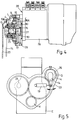
- Actuation of the lever 14 can be effected by any suitable device, such as a pneumatic or hydraulically operated actuator or the electric linear actuator 19 shown in Fig. 5, in a control arrangement which will be described in greater detail later.
- a pneumatic or hydraulically operated actuator or the electric linear actuator 19 shown in Fig. 5 in a control arrangement which will be described in greater detail later.
- FIG. 2 With carrier 10 stationary there will be a straight speed reduction (step-down) between the sunwheel assembly 3 and the annulus gear 11 and the datum indicators I S and I A for the sunwheel and the annulus will be aligned, I S being set precisely with regard to a crankshaft datum.
- the annulus gear 11 will be caused to lead ( ⁇ L ) or lag ( ⁇ R ) the sunwheel assembly 3 by a small desired amount, dependent on the direction of swing of the lever 14.
- the lever 14 may be provided with swinging movements up to 90°, but usually about 10° should be sufficient.
- Fig. 3 shows a gear device G in accordance with Fig. 1 utilised in an engine camshaft 21 - similar references are used as in Fig. 1.
- the radial wall 16A of the annulus gear 11 is integral with the camshaft 21, the wall 16A being located close to a camshaft support block 22 mounted on the engine cylinder head (not shown).
- Lubricating oil for the epicyclic gear 1 is taken from the oil gallery 23 of the camshaft via ducts 24 and 25.
- the drive through the epicyclic gear 1 is shown in thick arrowed-lines in Fig. 3.
- Fig. 4 shows the gear device G fitted on the injection pump 26 of a diesel engine, the location of the pump 26 on the engine E, being shown in Fig. 5.
- the gear G is exactly in accordance with Fig. 1, with the hub 16 fixed directly onto an external stub portion 27 of the pump shaft so that the gear is positioned close to an end casing wall 28 of the pump.
- Lubrication to the epicyclic gear 1 can be via nozzle input 29 and duct 30.
- the position of the lever 14 is controlled by an electrical linear actuator 19 (Fig. 5) connected to the timing case cover 20.
- the actuator is connected to a 'black box' and powered by the vehicle battery.
- the actuator 19 positions the lever 14 as required up to 90° swing.
- the 'black box' monitors a number of engine operating parameters and sends a signal to the electrical actuator 19 to change the timing of fuel injection so as to be appropriate to the desired operating condition.
- the device provides accurate control of the angular relationship between the engine crankshaft and the fuel injection pump 26.
- This pump 26 is responsible for entering the supply of fuel to the injector atomisers. Without some form of timing control device, the relationship between the engine crankshaft and the instant that the fuel is injected into the combustion space is purely dependent upon the hydromechanical characteristics of the fuel system.
- timing device G By incorporating this timing device G it is possible to optimise the instant of injection with respect to many parameters, such as speed, load, air temperature, water temperature, throttle position etc thus enabling enhanced engine performance characteristics to be achieved.
- the input gear (4) of the pump 26 can be of smaller size (eg 34 tooth) compared to the prior art arrangements shown in Fig. 6 where this input gear P1 has 56 teeth: this enables a reduction in the overall width of the engine.
- Figs. 5 and 6 show the crankshaft gear K driving the input gear of the pump 26 via an idler gear.
- the overall diameter of the gear device G can be kept at a minimum thereby giving a compact device.
- the lever 14 is positioned close to the front of the epicyclic gear 1.
- Figs. 7 and 8 show an engine having a single overhead camshaft, fuel injection pump both with variable timing, plus an alternator and water pump drive.
- a conventional drive (Fig. 7) it is usual to have one drive belt or system 31 to drive low speed components such as fuel injection pumps 26 and camshafts 21, which run at half engine speed, and another 32 for high speed components, e.g. alternators 33, water pumps 34, which run at higher than engine speed, the drive being from the crankshaft pulley wheels or sprockets K1, or K2.
- low speed components such as fuel injection pumps 26 and camshafts 21, which run at half engine speed
- high speed components e.g. alternators 33, water pumps 34, which run at higher than engine speed
- crankshaft pulley/gear/sprocket etc has to be small in diameter in order that the camshaft or fuel injection pump pulley/sprocket (at twice the diameter of the crankshaft pulley) can be of reasonable size.
- the camshaft and fuel injection pump run at half crankshaft speed.
- crankshaft pulley K1 to be enlarged to that all components can be driven on a single drive system 31A as shown in Fig. 8.
- the fuel injection pump and camshaft drive pulley/sprocket 4 will be operating at a much higher speed in this case, the correct ratio of 1:2 is recovered by the speed step-down facility within the variable timing device provided at these items.
- Figs. 9 and 10 similarly show the advantages of employing the variable timing devices G in a V-type engine.
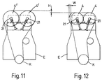
- camshafts On a double overhead camshaft drive it is usual to have the camshafts disposed as shown in Fig. 11.
- the camshaft centres are determined by the diameter of the drive pulleys/sprockets 4' which are adjacent.
- the diameter of the pulleys/sprockets 4' is fixed at twice the diameter of the crankshaft pulley/sprocket K for a 4-stroke engine.
- the height of the engine is also usually determined by the diameter of these pulleys/sprockets 4'.
- variable timing device G fitted to both camshafts 21 can allow the diameter of the camshaft drive pulley/sprockets 4' to be reduced and this is shown in Fig. 12. Although this would mean the camshaft drive pulley/sprocket 4 will be operating at a higher speed, the correct ratio of camshaft speed to crankshaft speed of 1:2 is recovered by the speed step-down facility within the variable timing device G.
- An advantage that stems from reducing camshaft centres is that more flexibility in determining inlet and exhaust valve inclination is achieved which should lead to better engine performance.
- the reduction in engine height leads to better engine packaging, particularly with regard to passenger car under bonnet clearances.
- step-up variable gear devices at the high speed components instead of the step-down device at the low speed components still with only a single drive system (belt) employed.
- the actual speed change obtained from the gear 1 could be selected as appropriate, and for some components such as engine superchargers a higher step-up may be required.
Landscapes
- Engineering & Computer Science (AREA)
- General Engineering & Computer Science (AREA)
- Mechanical Engineering (AREA)
- Chemical & Material Sciences (AREA)
- Combustion & Propulsion (AREA)
- Valve Device For Special Equipments (AREA)
- Valve-Gear Or Valve Arrangements (AREA)
- Structure Of Transmissions (AREA)
- Retarders (AREA)
- Fluid-Driven Valves (AREA)
- Magnetically Actuated Valves (AREA)
- High-Pressure Fuel Injection Pump Control (AREA)
- Hybrid Electric Vehicles (AREA)
- Preparation Of Compounds By Using Micro-Organisms (AREA)
Applications Claiming Priority (3)
| Application Number | Priority Date | Filing Date | Title |
|---|---|---|---|
| GB9203921 | 1992-02-24 | ||
| GB929203921A GB9203921D0 (en) | 1992-02-24 | 1992-02-24 | Variable timing gear device |
| EP93903279A EP0628132B1 (fr) | 1992-02-24 | 1993-02-12 | Dispositif de distribution variable |
Related Parent Applications (1)
| Application Number | Title | Priority Date | Filing Date |
|---|---|---|---|
| EP93903279.3 Division | 1993-02-12 |
Publications (2)
| Publication Number | Publication Date |
|---|---|
| EP0715059A2 true EP0715059A2 (fr) | 1996-06-05 |
| EP0715059A3 EP0715059A3 (fr) | 1997-01-22 |
Family
ID=10710946
Family Applications (2)
| Application Number | Title | Priority Date | Filing Date |
|---|---|---|---|
| EP96102451A Withdrawn EP0715059A3 (fr) | 1992-02-24 | 1993-02-12 | Moteur à combustion interne |
| EP93903279A Expired - Lifetime EP0628132B1 (fr) | 1992-02-24 | 1993-02-12 | Dispositif de distribution variable |
Family Applications After (1)
| Application Number | Title | Priority Date | Filing Date |
|---|---|---|---|
| EP93903279A Expired - Lifetime EP0628132B1 (fr) | 1992-02-24 | 1993-02-12 | Dispositif de distribution variable |
Country Status (18)
| Country | Link |
|---|---|
| US (1) | US5533475A (fr) |
| EP (2) | EP0715059A3 (fr) |
| JP (1) | JPH07503770A (fr) |
| KR (1) | KR950700479A (fr) |
| AT (1) | ATE155206T1 (fr) |
| AU (2) | AU662209B2 (fr) |
| BG (1) | BG62218B1 (fr) |
| BR (1) | BR9305998A (fr) |
| CA (1) | CA2128223C (fr) |
| CZ (1) | CZ284139B6 (fr) |
| DE (1) | DE69312060T2 (fr) |
| ES (1) | ES2105221T3 (fr) |
| GB (1) | GB9203921D0 (fr) |
| HU (1) | HU213341B (fr) |
| RU (1) | RU2109145C1 (fr) |
| SK (1) | SK88794A3 (fr) |
| WO (1) | WO1993017226A1 (fr) |
| ZA (2) | ZA931075B (fr) |
Cited By (6)
| Publication number | Priority date | Publication date | Assignee | Title |
|---|---|---|---|---|
| EP1085194A1 (fr) * | 1999-09-14 | 2001-03-21 | Volkswagen Aktiengesellschaft | Méthode pour surveiller l'usure d'une courroie dentée équipant un arbre à cames de conduite |
| EP1717425A2 (fr) | 2005-04-28 | 2006-11-02 | Yamaha Hatsudoki Kabushiki Kaisha | Moteur à combustion interne |
| WO2007068576A1 (fr) * | 2005-12-15 | 2007-06-21 | Schaeffler Kg | Dispositif de reglage d'un arbre a cames |
| EP1980743A1 (fr) * | 2007-04-10 | 2008-10-15 | Nissan Motor Co., Ltd. | Dispositif de d'entrainement de pompe à carburant |
| WO2011161407A1 (fr) * | 2010-06-21 | 2011-12-29 | Antonov Automotive Technologies Ltd | Unité de transmission à des fins de transmission d'entraînement d'un moteur à un accessoire de moteur |
| CN101285443B (zh) * | 2007-04-10 | 2012-06-13 | 日产自动车株式会社 | 燃料泵驱动装置 |
Families Citing this family (13)
| Publication number | Priority date | Publication date | Assignee | Title |
|---|---|---|---|---|
| FR2706965A1 (en) * | 1993-06-23 | 1994-12-30 | Inst Francais Du Petrole | System for angular offset between two rotating shafts of an internal combustion engine |
| DE19624240C5 (de) * | 1996-06-18 | 2011-07-28 | Daimler AG, 70327 | Brennkraftmaschine |
| FR2809152B1 (fr) | 2000-05-17 | 2002-11-08 | Timothee Biel | Dispositif pour produire un dephasage entre deux elements d'une transmission |
| RU2195562C2 (ru) * | 2000-06-19 | 2002-12-27 | Фомин Николай Александрович | Механизм сдвига фаз впуска на распределительном валу |
| RU2235896C2 (ru) * | 2002-08-05 | 2004-09-10 | Фомин Николай Александрович | Механизм сдвига фаз впуска с нажимным диском |
| DE10352255B4 (de) * | 2003-11-08 | 2017-03-09 | Schaeffler Technologies AG & Co. KG | Verstellvorrichtung zum Verstellen der relativen Drehwinkellage einer Nockenwelle gegenüber einer Kurbelwelle einer Brennkraftmaschine |
| US7980975B2 (en) * | 2007-11-16 | 2011-07-19 | Grossman Victor A | Drive configuration and method thereof |
| RU2476691C2 (ru) * | 2009-03-26 | 2013-02-27 | Федеральное государственное унитарное предприятие "Центральный ордена Трудового Красного Знамени научно-исследовательский автомобильный и автомоторный институт "НАМИ" | Регулируемый привод клапана впуска рабочей среды в цилиндр двигателя |
| JP2015500411A (ja) * | 2011-10-18 | 2015-01-05 | ライトセイル エナジー インコーポレイテッド | 圧縮気体エネルギー貯蔵システム |
| CN104329174B (zh) * | 2014-09-10 | 2019-02-26 | 江苏科技大学 | 一种多缸柴油机供油提前角的调整装置及方法 |
| CZ308187B6 (cs) * | 2015-09-04 | 2020-02-12 | Ĺ KODA AUTO a.s. | Zařízení pro variabilní natáčení vačkové hřídele spalovacího motoru |
| DE102017003390A1 (de) * | 2016-04-26 | 2017-10-26 | Ford Global Technologies, Llc | Per Zahnrad angetriebene Dieselkraftstoff-Einspritzpumpe eines Motors |
| US10422253B2 (en) | 2016-04-26 | 2019-09-24 | Ford Global Technologies, Llc | Cam drive system for an engine |
Family Cites Families (8)
| Publication number | Priority date | Publication date | Assignee | Title |
|---|---|---|---|---|
| DE2628680A1 (de) * | 1976-06-25 | 1977-12-29 | Volkswagenwerk Ag | Zahnriementrieb fuer dieselmotoren |
| JPS5452218A (en) * | 1977-09-30 | 1979-04-24 | Toyota Central Res & Dev Lab Inc | Internal-combustion engine |
| US4747375A (en) * | 1982-08-31 | 1988-05-31 | Williams John K | Device for controlling the phased displacement of rotating shafts |
| DE8417223U1 (de) * | 1984-06-06 | 1989-07-20 | Dr.Ing.H.C. F. Porsche Ag, 7000 Stuttgart | Nockenwellenantrieb einer Brennkraftmaschine |
| JP2610121B2 (ja) * | 1985-05-14 | 1997-05-14 | ヤマハ発動機株式会社 | 内燃機関の開弁時期調節装置 |
| DE3737602A1 (de) * | 1987-11-05 | 1989-05-18 | Interatom | Einrichtung zum veraendern der steuerzeiten der ventile einer verbrennungskraftmaschine mittels eines differentialgetriebes |
| JPH04241709A (ja) * | 1991-01-11 | 1992-08-28 | Toyota Motor Corp | 軸間位相変換装置 |
| DE4104872A1 (de) * | 1991-02-18 | 1992-08-20 | Wolfgang Schieck | Verfahren zur drosselfreien laststeuerung fuer ottomotoren |
-
1992
- 1992-02-24 GB GB929203921A patent/GB9203921D0/en active Pending
-
1993
- 1993-02-12 AT AT93903279T patent/ATE155206T1/de not_active IP Right Cessation
- 1993-02-12 SK SK887-94A patent/SK88794A3/sk unknown
- 1993-02-12 CA CA002128223A patent/CA2128223C/fr not_active Expired - Fee Related
- 1993-02-12 AU AU34613/93A patent/AU662209B2/en not_active Ceased
- 1993-02-12 JP JP5513564A patent/JPH07503770A/ja active Pending
- 1993-02-12 WO PCT/GB1993/000301 patent/WO1993017226A1/fr not_active Ceased
- 1993-02-12 DE DE69312060T patent/DE69312060T2/de not_active Expired - Fee Related
- 1993-02-12 HU HU9402113A patent/HU213341B/hu not_active IP Right Cessation
- 1993-02-12 EP EP96102451A patent/EP0715059A3/fr not_active Withdrawn
- 1993-02-12 BR BR9305998A patent/BR9305998A/pt not_active Application Discontinuation
- 1993-02-12 RU RU94041754A patent/RU2109145C1/ru active
- 1993-02-12 EP EP93903279A patent/EP0628132B1/fr not_active Expired - Lifetime
- 1993-02-12 CZ CZ941772A patent/CZ284139B6/cs unknown
- 1993-02-12 US US08/295,840 patent/US5533475A/en not_active Expired - Fee Related
- 1993-02-12 ES ES93903279T patent/ES2105221T3/es not_active Expired - Lifetime
- 1993-02-16 ZA ZA931075A patent/ZA931075B/xx unknown
-
1994
- 1994-08-11 ZA ZA946053A patent/ZA946053B/xx unknown
- 1994-08-19 BG BG98988A patent/BG62218B1/bg unknown
- 1994-08-23 KR KR1019940702934A patent/KR950700479A/ko not_active Ceased
-
1995
- 1995-07-06 AU AU24842/95A patent/AU668517B2/en not_active Ceased
Cited By (9)
| Publication number | Priority date | Publication date | Assignee | Title |
|---|---|---|---|---|
| EP1085194A1 (fr) * | 1999-09-14 | 2001-03-21 | Volkswagen Aktiengesellschaft | Méthode pour surveiller l'usure d'une courroie dentée équipant un arbre à cames de conduite |
| EP1717425A2 (fr) | 2005-04-28 | 2006-11-02 | Yamaha Hatsudoki Kabushiki Kaisha | Moteur à combustion interne |
| EP1717425A3 (fr) * | 2005-04-28 | 2009-09-23 | Yamaha Hatsudoki Kabushiki Kaisha | Moteur à combustion interne |
| WO2007068576A1 (fr) * | 2005-12-15 | 2007-06-21 | Schaeffler Kg | Dispositif de reglage d'un arbre a cames |
| US8104439B2 (en) | 2005-12-15 | 2012-01-31 | Schaeffler Technologies Gmbh & Co. Kg | Camshaft adjuster |
| EP1980743A1 (fr) * | 2007-04-10 | 2008-10-15 | Nissan Motor Co., Ltd. | Dispositif de d'entrainement de pompe à carburant |
| US7765989B2 (en) | 2007-04-10 | 2010-08-03 | Nissan Motor Co., Ltd. | Fuel pump driving device |
| CN101285443B (zh) * | 2007-04-10 | 2012-06-13 | 日产自动车株式会社 | 燃料泵驱动装置 |
| WO2011161407A1 (fr) * | 2010-06-21 | 2011-12-29 | Antonov Automotive Technologies Ltd | Unité de transmission à des fins de transmission d'entraînement d'un moteur à un accessoire de moteur |
Also Published As
| Publication number | Publication date |
|---|---|
| RU94041754A (ru) | 1996-06-20 |
| AU668517B2 (en) | 1996-05-09 |
| SK88794A3 (en) | 1995-04-12 |
| HUT67450A (en) | 1995-04-28 |
| ZA931075B (en) | 1994-08-16 |
| ES2105221T3 (es) | 1997-10-16 |
| AU3461393A (en) | 1993-09-13 |
| DE69312060T2 (de) | 1998-02-19 |
| EP0628132B1 (fr) | 1997-07-09 |
| EP0628132A1 (fr) | 1994-12-14 |
| RU2109145C1 (ru) | 1998-04-20 |
| JPH07503770A (ja) | 1995-04-20 |
| BG98988A (bg) | 1995-06-30 |
| AU662209B2 (en) | 1995-08-24 |
| BR9305998A (pt) | 1997-09-16 |
| DE69312060D1 (de) | 1997-08-14 |
| KR950700479A (ko) | 1995-01-16 |
| HU9402113D0 (en) | 1994-09-28 |
| AU2484295A (en) | 1995-09-14 |
| CZ284139B6 (cs) | 1998-08-12 |
| ATE155206T1 (de) | 1997-07-15 |
| EP0715059A3 (fr) | 1997-01-22 |
| BG62218B1 (bg) | 1999-05-31 |
| WO1993017226A1 (fr) | 1993-09-02 |
| ZA946053B (en) | 1994-08-22 |
| HU213341B (en) | 1997-05-28 |
| CZ177294A3 (en) | 1995-06-14 |
| CA2128223A1 (fr) | 1993-09-02 |
| CA2128223C (fr) | 1998-06-09 |
| GB9203921D0 (en) | 1992-04-08 |
| US5533475A (en) | 1996-07-09 |
Similar Documents
| Publication | Publication Date | Title |
|---|---|---|
| EP0715059A2 (fr) | Moteur à combustion interne | |
| US5605120A (en) | Method and a device for changing the compression ratio in an internal combustion engine | |
| US5143033A (en) | Internal combustion engine having an integral cylinder head | |
| JPH0830402B2 (ja) | 内燃機関のカム軸駆動装置 | |
| US5860402A (en) | Oil pump drive for engine | |
| US5873336A (en) | Cam drive system for engine | |
| US6189498B1 (en) | Cam shaft drive for engine | |
| US6213072B1 (en) | V-shaped internal combustion engine | |
| US5144920A (en) | Automatic timing governor between crankshaft and camshafts, operating by means of actuators on the shaft connecting chain | |
| US3473399A (en) | Belt drive and tensioning means | |
| US3482553A (en) | Internal combustion engine overhead camshaft drive means | |
| US6325031B1 (en) | Engine cam shaft drive incorporating VVT | |
| JPH0666112A (ja) | V型エンジン | |
| DE50007057D1 (de) | Kettenspanner für eine kolbenbrennkraftmaschine mit variablem brennraum | |
| US3422806A (en) | Internal combustion engine | |
| JP2604397B2 (ja) | V型エンジン | |
| CN1112643A (zh) | 四冲程内燃机凸轮驱动零件的润滑装置 | |
| KR100302486B1 (ko) | 캠축구동기어 | |
| JP3533744B2 (ja) | Sohcエンジン | |
| JPH0337306A (ja) | Dohcエンジンのカム軸軸受構造 | |
| JP2516488Y2 (ja) | Dohcエンジンのシリダヘッド | |
| JPS63195305A (ja) | 自動二輪車用エンジンのカム軸駆動機構 | |
| JPH02275020A (ja) | バーチカルクランク軸エンジン | |
| KR960034689A (ko) | Ohc 디젤 엔진 | |
| KR20030016886A (ko) | 가변밸브타이밍 장치의 응답성 향상을 위한 스프로켓의장착구조 |
Legal Events
| Date | Code | Title | Description |
|---|---|---|---|
| PUAI | Public reference made under article 153(3) epc to a published international application that has entered the european phase |
Free format text: ORIGINAL CODE: 0009012 |
|
| 17P | Request for examination filed |
Effective date: 19960219 |
|
| AC | Divisional application: reference to earlier application |
Ref document number: 628132 Country of ref document: EP |
|
| AK | Designated contracting states |
Kind code of ref document: A2 Designated state(s): AT DE ES FR GB IT NL SE |
|
| PUAL | Search report despatched |
Free format text: ORIGINAL CODE: 0009013 |
|
| AK | Designated contracting states |
Kind code of ref document: A3 Designated state(s): AT DE ES FR GB IT NL SE |
|
| 17Q | First examination report despatched |
Effective date: 19980701 |
|
| RAP1 | Party data changed (applicant data changed or rights of an application transferred) |
Owner name: PERKINS ENGINES COMPANY LIMITED |
|
| STAA | Information on the status of an ep patent application or granted ep patent |
Free format text: STATUS: THE APPLICATION IS DEEMED TO BE WITHDRAWN |
|
| 18D | Application deemed to be withdrawn |
Effective date: 20010105 |