EP0718962A1 - Dispositif et methode d'abaissement de la tension induite d'un moteur a induction - Google Patents
Dispositif et methode d'abaissement de la tension induite d'un moteur a induction Download PDFInfo
- Publication number
- EP0718962A1 EP0718962A1 EP95914534A EP95914534A EP0718962A1 EP 0718962 A1 EP0718962 A1 EP 0718962A1 EP 95914534 A EP95914534 A EP 95914534A EP 95914534 A EP95914534 A EP 95914534A EP 0718962 A1 EP0718962 A1 EP 0718962A1
- Authority
- EP
- European Patent Office
- Prior art keywords
- windings
- winding
- connection
- motor
- speed
- Prior art date
- Legal status (The legal status is an assumption and is not a legal conclusion. Google has not performed a legal analysis and makes no representation as to the accuracy of the status listed.)
- Granted
Links
- 230000006698 induction Effects 0.000 title claims abstract description 79
- 238000000034 method Methods 0.000 title claims description 11
- 238000004804 winding Methods 0.000 claims abstract description 398
- 230000015556 catabolic process Effects 0.000 description 17
- 238000010586 diagram Methods 0.000 description 16
- 101150013204 MPS2 gene Proteins 0.000 description 13
- 230000006870 function Effects 0.000 description 12
- 230000004044 response Effects 0.000 description 4
- 239000004020 conductor Substances 0.000 description 3
- 238000009413 insulation Methods 0.000 description 3
- 230000015654 memory Effects 0.000 description 3
- 230000007935 neutral effect Effects 0.000 description 2
- 230000003213 activating effect Effects 0.000 description 1
- 230000000694 effects Effects 0.000 description 1
- 230000005284 excitation Effects 0.000 description 1
- 238000012545 processing Methods 0.000 description 1
- 238000000926 separation method Methods 0.000 description 1
Images



Classifications
-
- H—ELECTRICITY
- H02—GENERATION; CONVERSION OR DISTRIBUTION OF ELECTRIC POWER
- H02P—CONTROL OR REGULATION OF ELECTRIC MOTORS, ELECTRIC GENERATORS OR DYNAMO-ELECTRIC CONVERTERS; CONTROLLING TRANSFORMERS, REACTORS OR CHOKE COILS
- H02P25/00—Arrangements or methods for the control of AC motors characterised by the kind of AC motor or by structural details
- H02P25/16—Arrangements or methods for the control of AC motors characterised by the kind of AC motor or by structural details characterised by the circuit arrangement or by the kind of wiring
- H02P25/18—Arrangements or methods for the control of AC motors characterised by the kind of AC motor or by structural details characterised by the circuit arrangement or by the kind of wiring with arrangements for switching the windings, e.g. with mechanical switches or relays
- H02P25/20—Arrangements or methods for the control of AC motors characterised by the kind of AC motor or by structural details characterised by the circuit arrangement or by the kind of wiring with arrangements for switching the windings, e.g. with mechanical switches or relays for pole-changing
-
- H—ELECTRICITY
- H02—GENERATION; CONVERSION OR DISTRIBUTION OF ELECTRIC POWER
- H02K—DYNAMO-ELECTRIC MACHINES
- H02K17/00—Asynchronous induction motors; Asynchronous induction generators
- H02K17/02—Asynchronous induction motors
- H02K17/12—Asynchronous induction motors for multi-phase current
- H02K17/14—Asynchronous induction motors for multi-phase current having windings arranged for permitting pole-changing
-
- H—ELECTRICITY
- H02—GENERATION; CONVERSION OR DISTRIBUTION OF ELECTRIC POWER
- H02P—CONTROL OR REGULATION OF ELECTRIC MOTORS, ELECTRIC GENERATORS OR DYNAMO-ELECTRIC CONVERTERS; CONTROLLING TRANSFORMERS, REACTORS OR CHOKE COILS
- H02P1/00—Arrangements for starting electric motors or dynamo-electric converters
- H02P1/16—Arrangements for starting electric motors or dynamo-electric converters for starting dynamo-electric motors or dynamo-electric converters
- H02P1/26—Arrangements for starting electric motors or dynamo-electric converters for starting dynamo-electric motors or dynamo-electric converters for starting an individual polyphase induction motor
- H02P1/38—Arrangements for starting electric motors or dynamo-electric converters for starting dynamo-electric motors or dynamo-electric converters for starting an individual polyphase induction motor by pole-changing
-
- H—ELECTRICITY
- H02—GENERATION; CONVERSION OR DISTRIBUTION OF ELECTRIC POWER
- H02P—CONTROL OR REGULATION OF ELECTRIC MOTORS, ELECTRIC GENERATORS OR DYNAMO-ELECTRIC CONVERTERS; CONTROLLING TRANSFORMERS, REACTORS OR CHOKE COILS
- H02P23/00—Arrangements or methods for the control of AC motors characterised by a control method other than vector control
-
- H—ELECTRICITY
- H02—GENERATION; CONVERSION OR DISTRIBUTION OF ELECTRIC POWER
- H02P—CONTROL OR REGULATION OF ELECTRIC MOTORS, ELECTRIC GENERATORS OR DYNAMO-ELECTRIC CONVERTERS; CONTROLLING TRANSFORMERS, REACTORS OR CHOKE COILS
- H02P25/00—Arrangements or methods for the control of AC motors characterised by the kind of AC motor or by structural details
- H02P25/16—Arrangements or methods for the control of AC motors characterised by the kind of AC motor or by structural details characterised by the circuit arrangement or by the kind of wiring
- H02P25/18—Arrangements or methods for the control of AC motors characterised by the kind of AC motor or by structural details characterised by the circuit arrangement or by the kind of wiring with arrangements for switching the windings, e.g. with mechanical switches or relays
- H02P25/184—Arrangements or methods for the control of AC motors characterised by the kind of AC motor or by structural details characterised by the circuit arrangement or by the kind of wiring with arrangements for switching the windings, e.g. with mechanical switches or relays wherein the motor speed is changed by switching from a delta to a star, e.g. wye, connection of its windings, or vice versa
-
- H—ELECTRICITY
- H02—GENERATION; CONVERSION OR DISTRIBUTION OF ELECTRIC POWER
- H02P—CONTROL OR REGULATION OF ELECTRIC MOTORS, ELECTRIC GENERATORS OR DYNAMO-ELECTRIC CONVERTERS; CONTROLLING TRANSFORMERS, REACTORS OR CHOKE COILS
- H02P25/00—Arrangements or methods for the control of AC motors characterised by the kind of AC motor or by structural details
- H02P25/16—Arrangements or methods for the control of AC motors characterised by the kind of AC motor or by structural details characterised by the circuit arrangement or by the kind of wiring
- H02P25/18—Arrangements or methods for the control of AC motors characterised by the kind of AC motor or by structural details characterised by the circuit arrangement or by the kind of wiring with arrangements for switching the windings, e.g. with mechanical switches or relays
- H02P25/188—Arrangements or methods for the control of AC motors characterised by the kind of AC motor or by structural details characterised by the circuit arrangement or by the kind of wiring with arrangements for switching the windings, e.g. with mechanical switches or relays wherein the motor windings are switched from series to parallel or vice versa to control speed or torque
Definitions
- This invention relates to a drive system for AC motors, and more particularly to a control system for reducing induced voltage to be generated in a winding for low-speed revolution of the induction motor.
- the induction motor can produce a large torque at low-speed revolutions by switching the primary windings with the same primary current.
- the induction motor has windings forming a Y-Y connection, with first terminals supplying electric current to the entire part of the primary windings of U-, V- and W-phases and second terminals provided at an intermediate portion of each winding so as to supply electric current to only a part of each winding.
- Changeover of the primary windings is carried out in such a manner that electric power is exclusively supplied from the first terminals to supply electric current to the whole of each winding when the motor is to be operated in the low-speed region, while electric power is exclusively supplied from the second terminals to supply electric power to the limited part of each winding when the motor is to be operated in the high-speed region.
- Such a changeover of the primary windings causes the change of excitation.
- the secondary current of the rotor and the output torque can be enlarged by increasing the number of turns of the primary winding under the same current.
- the above-described conventional induction motor has a problem such that driving the winding for high-speed revolutions of the induction motor cause the winding for low-speed revolutions to induce voltage, which may cause its dielectric breakdown.
- Fig. 12 is a diagram illustrating an induced voltage in a conventional Y-connection type induction motor.
- the windings of U-, V- and W-phases are respectively constituted of a winding for high-speed revolution of motor C1 and a winding for low-speed revolution of motor C2 and serially connected to forms a Y connection.
- the winding for high-speed revolution of motor C1 has intermediate terminals U2, V2 and W2, while the winding for low-speed revolution of motor C2 has end terminals U1, V1 and W1.
- the induced voltage will be explained taking the case of the U-phase winding. While the winding for high-speed revolution of motor is in operation, the intermediate terminal U2 is used to exclusively supply electric current to the winding for high-speed revolution of motor C1, and no electric current is supplied to the winding for low-speed revolution of motor C2. However, the winding for low-speed revolution of motor C2 is made to induce voltage due to the voltage applied to the winding for high-speed revolution of motor C1. This induced voltage is proportional to the number of turns of the winding for high-speed revolution of motor C1 and that of the winding for low-speed revolution of motor C2.
- the number of turns number of the low-seed winding C2 is set larger than that of the winding for high-speed revolution of motor C1. Therefore, the voltage induced in the winding for low-speed revolution of motor C2 is higher than the voltage applied to the winding for high-speed revolution of motor C1.
- An object of the present invention is to provide an induced voltage reduction method and an induced voltage reduction apparatus capable of reducing the induced voltage in the winding for low-speed revolution of motor while the induction motor is operated using the winding for in the high-speed revolutions.
- a first aspect of the present invention provides an induced voltage reduction method for an induction motor having a plurality of windings of different phases in Y connection and designed for having its drive controlled by changing the connection of the windings of the induction motor, wherein the winding for high-speed revolutions is disconnected from other windings during winding for high-speed revolution of motor is in operation, and electric voltage is applied to the winding for high-speed revolution of motor, thereby reducing absolute value of induced voltage in the disconnected other windings.
- a second aspect of the present invention provides an induced voltage reduction apparatus for an induction motor having a plurality of windings of different phases in Y connection and designed for having its drive controlled by changing the connection of winding of the induction motor, the apparatus comprising: changeover means for changing the connection of the windings; and control means for controlling changeover operation of the changeover means; wherein the changeover means is controlled by the control means in such a manner that a winding for high-speed revolution of motor is disconnected from other windings while a winding for high-speed revolution of motor is in operation, thereby reducing absolute value of induced voltage in the disconnected other windings.
- each winding of corresponding phase comprises a plurality of disconnectable windings having a predetermined number-of-turns ratio, and the disconnectable windings are connected to changeover switches constituting the changeover means so that the disconnectable windings are connected or disconnected by opening or closing the changeover switches.
- a third aspect of the present invention provides an induced voltage reduction method for an induction motor having a plurality of windings of different phases in Y connection and designed for having its drive controlled by changing the connection of the windings of the induction motor, wherein the connection of windings is partially changed from the Y connection to ⁇ connection while a winding for high-speed revolution of motor is driven to reduce number-of-turns ratio of a winding for low-speed revolution of motor to a winding for high-speed revolution of motor, thereby reducing absolute value of induced voltage in the winding for low-speed revolution of motor.
- a fourth aspect of the present invention provides an induced voltage reduction apparatus for an induction motor having a plurality of windings of different phases in Y connection and designed for having its drive controlled by changing the connection of the windings of the induction motor, the apparatus comprising: changeover means for changing the connection of windings; and control means for controlling changeover operation of the changeover means, wherein the changeover means is controlled by the control means in such a manner that the connection of the windings is partially changed from the Y connection to a ⁇ connection while a winding for high-speed revolution of motor is in operation, thereby reducing absolute value of an induced voltage in a winding for low-speed revolution of motor.
- each winding of corresponding phase comprises a plurality of disconnectable windings having a predetermined number-of-turns ratio, and ends of the disconnectable windings are connected to changeover switches constituting the switching means so that the disconnectable windings are connected or disconnected by opening or closing the changeover switches, thereby changing the part of the connection of windings from the Y connection to the ⁇ connection.
- control means controls the changeover means in accordance with the speed of the induction motor.
- the switching means of the present invention is a means having a function of changing the connection of the windings of different phases, and includes changeover switches for connecting and disconnecting windings. These changeover switches connect or disconnect the plural disconnectable windings constituting the windings of different phases in the case of the second aspect of present invention, and also connect or disconnect the ends of the windings of different phases in the case of the fourth aspect of the present invention. Furthermore, the changeover means is capable of connecting and disconnecting the windings of different phases, as well as capable of connecting and disconnecting the windings to or from the power unit.
- the changeover means can be constituted of conductors such as relays.
- control means of the present invention is a means having a function of controlling changeover operation of the changeover means.
- This control means has a function of setting the contents and timings of the changeover operation in accordance with the speed of the induction motor obtainable from a speed sensor or the like and a function for sending out the control signal to the changeover means.
- the control means may be constituted of a CPU performing various processings and memories for storing the content of the switching operation, etc.
- windings except of the winding for high-speed revolution of motor of each phase is disconnected from each windings when the motor is operated by the winding for high-speed revolution of motor.
- This disconnection of winding has an effect of dividing the induced voltage into each disconnected windings by the unit of winding when the voltage is induced by the application of a voltage to the winding for high-speed revolution of motor.
- Such division of the induced voltage into the each disconnected windings reduces absolute value of the induced voltage. And, the reduction of the induced voltage prevents the dielectric breakdown.
- the control means controls the changeover means in the drive condition of winding for high speed revolution the induction motor.
- the changeover means disconnects the winding for high-speed revolution of motor from other windings in each phase of the induction motor.
- This kind of separation of the winding can be performed by dividing each phase winding into a plurality of windings so as to have a predetermined number of turns ratio, and connecting or disconnecting these windings by opening or closing the changeover switches constituting the switching means.
- Such disconnection of winding makes it possible to divide the induced voltage into voltages corresponding to the separated windings when an electric voltage is applied to the winding for high-speed revolution of motor. Division of the induced voltage reduces absolute value of the induced voltage. And, the reduction of the induced voltage prevents the dielectric breakdown.
- the connection of the windings is partially from the Y connection to the ⁇ connection while the motor is operated in a driving of winding for high-speed revolution.
- the ⁇ connection reduces number-of-turns ratio of the winding for low-speed revolution of motor to the winding for high-speed revolution of motor and also reduce the absolute value of the voltage induced in the winding for low-speed revolution of motor. And, the reduction of the induced voltage prevents the dielectric breakdown.
- the control means controls the changeover means in a driving of winding for high-speed revolution of the induction motor.
- the changeover means partially changes the connection of the windings from the Y connection to the ⁇ connection in a driving of windings for high-speed revolution of the induction motor.
- the change of connection pattern of windings from the Y connection to the ⁇ connection can be made by dividing each winding of corresponding phase into a plurality of windings at a predetermined number-of-turns ratio, and connecting or disconnecting the ends of the windings by opening or closing the changeover switches constituting the switching means.
- the ⁇ connection uses a larger number of windings than that used in the Y connection. As a result, the number-of-turns ratio of the winding for low-speed revolution of motor to the winding for high-speed revolution of motor is reduced, and the absolute value of the induced voltage in the winding for low-speed revolution of motor is reduced. And, the reduction of the induced voltage prevents the dielectric breakdown.
- Fig. 1 is a block diagram showing an arrangement of the first embodiment of the present invention for performing an induced voltage reduction method for an induction motor, and also an arrangement of a first embodiment of the present invention for obtaining an induced voltage reduction apparatus for the induction motor.
- the induction motor shown in Fig. 1 comprises a power unit (not shown) and a Y-Y winding (i.e. star-star winding).
- This Y-Y winding type induction motor is driven by a drive system generally known as a Y-Y winding switching system.
- C1 through C3 represent windings of a stator in the induction motor.
- Reference numeral 1 represents a changeover circuit for switching these windings, while S1 and S2 represent changeover switches.
- Reference numeral 2 represents a control circuit for controlling the changeover circuit 1.
- Reference numeral 3 represents a speed sensor for detecting a rotational speed of an induction motor.
- the changeover circuit 1 and the changeover switches S1 and S2 are collectively treated as a switching means.
- the induction motor in the case disclosed in the drawing, has a winding connection of three phases (i.e. U phase, V phase and W phase).
- Each phase comprises a plurality of windings C1, C2 and C3 separable from each other.
- the U-phase winding is explained as an example.
- One end of the winding C1 of one phase is connected to one end of other windings C1 of other-phase, constituting a middle point.
- the other end of the winding C1 is connected to one end of the winding C2 via a changeover switch S1, and is also connected to the power unit (i.e. R phase in the drawing) via a changeover switch S2.
- the other end of the winding C2 is connected to one end of the winding C3 via the changeover switch S2. And, the other end of the winding C3 is connected to the power unit (i.e. R phase in the drawing) via the changeover switch S1.
- the V-phase winding and W-phase windings are arranged in the same manner as the U-phase winding, with the other ends of winding C1 and winding for low-speed revolution of motor C3 connected to R- and T-phases of the power unit, respectively.
- the winding C1 constitutes a winding for high-speed revolution of motor
- the windings C2 and C3 constitute a winding for low-speed revolution of motor.
- the number of disconnection of windings and the number of turns of winding used for constituting each-phase winding for low-speed revolution of motor may be determined by taking account of various conditions such as the output characteristics of the induction motor and an absolute value of the induced voltage to be generated in the winding for low-speed revolution of motor.
- the relation among the disconnected number of winding for low-speed revolution of motor, the separable of windings, and the induced voltage will be explained later in the section explaining the function of the embodiment.
- the changeover switches S1 and S2, interposed between, windings can be constituted by conductors, such as relays, which are opened or closed in response to the switching signal supplied from the changeover circuit 1.
- the switching signal, supplied from the changeover circuit 1 to respective changeover switches S1 and S2, is represented as an arrow marked by "*" in Fig. 1.
- the changeover circuit 1 constituting a switching means together with the changeover switches S1 and S2, executes the switching operation of the winding using the changeover switches S1 and S2.
- the changeover switches S1 and S2 are simultaneously operated for switching operation.
- control circuit 2 is, for example, constituted by a processor (CPU), memories such as ROM and RAM, an A/D converter and others
- the control circuit 2 not only controls the power unit but controls the changeover circuit 1 in accordance with the speed of the induction motor.
- the speed of the induction motor can be detected from a speed sensor 3 attached to the induction motor.
- Fig.1 is a case where the winding for high-speed revolution of motor is constituted by the winding C1 and the winding for low-speed revolution of motor by the windings C2 and C3, it is needless to say that the discrimination of windings is not limited to this embodiment, and, it will be possible to vary change the number of disconnection the winding. Furthermore, a winding for providing a middle-speed region, or a speed between high-speed revolution and low-speed revolution, can be formed. Even in these cases, the other windings than the winding for high-speed revolution of motor should be separated at least while the winding for high-speed revolution of motor is driven.
- Fig. 2 shows one aspect of the winding connection in the first embodiment arrangement where one changeover switch S1 is turned on and the other changeover switch S2 is turned off.
- Fig. 3 shows another aspect of the winding connection in the first embodiment arrangement where one changeover switch S1 is turned off and the other changeover switch S2 is turned on.
- the turning-on operation of the changeover switch S1 causes the series connection of the windings C1 through C3 in each phase of the induction motor. Furthermore, the power unit supplies electric current to the terminal of the winding C3 for low-speed revolution of motor by turning on the changeover switch S1 and turning off the changeover switch S2, thereby exciting the winding C1 for high-speed revolution of motor and the windings C2 and C3 for low-speed revolution of motor to drive a winding for low-speed revolution of motor of the induction motor.
- the drive of winding for low-speed revolution of motor generates a high torque in the low-speed region.
- the motor can produce a high torque in the low-speed revolutions.
- the motor can produce a high torque in the high speed region.
- Fig. 11 also shows the output characteristics of the motor driven by the winding having the number of turns 2T, relative to the number of revolution. This output characteristics can be obtained when the winding for high-speed revolution of motor has the number of turns 2T, or when only the winding C2 is activated, or when the winding C2 having the number of turns 1T is activated together with the winding for high-speed revolution of motor, and so on.
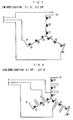
- Fig. 4 is a diagram illustrating an applied voltage to each winding and an induced voltage.
- Fig. 4(a) shows the voltage condition of the winding in the first embodiment
- Fig. 4(b) shows the voltage condition of the winding in the conventional induction motor.
- Fig. 4 shows the windings of only one phase, wherein the number of turns of winding C1 is 1T and the number of turns of the windings C2 and C3 is 2T, respectively. Accordingly, in this case, the number of turns becomes 1T in drive of the winding for high-speed revolution of motor and 5T in the drive of winding for low-speed revolution of motor, respectively.
- the induced voltage is generated in the windings C2 and C3 other than the winding for high-speed revolution of motor C1. Since the windings C2 and C3 are disconnected, an absolute value of the induced voltage is respectively 400 V which is proportional to 2T, number of turns of each winding.
- An absolute value of the induced voltage generated in the windings C2 and C3 other than the winding C1 for high-speed revolution of motor is within the threshold voltage causing the dielectric breakdown (e.g. approximately 600 V), whereby the dielectric breakdown can be prevented.
- the number of division the windings other than the winding for high-speed revolution of motor and the ratio of the number of turns of the divided winding to the number of turns of the winding for high-speed revolution of motor can be determined by taking account of various conditions of the induction motor, such as the applied voltage value and the withstanding threshold voltage value for the dielectric breakdown so that the absolute value of the induced voltage generated in each division of winding can be prevented from exceeding the withstanding threshold voltage value causing the dielectric breakdown.
- FIG. 5 is a block diagram showing an arrangement of the second embodiment for executing an induced voltage reduction method for an induction motor, and also a second embodiment for obtaining an induced voltage reduction apparatus for the induction motor.
- the induction motor shown in Fig. 2 comprises a power unit (not shown) and a Y-Y connection (i.e. star-star connection winding), in the same manner as the above-described first embodiment.
- This Y-Y connection winding can drive an induction motor using a drive system generally known as a Y-Y connection winding switching system.
- C1 through C3 represent windings of a stator in the induction motor.
- Reference numeral 1 represents a changeover circuit for switching these windings C1 through C3, while MMC1 and MMC2 represent changeover circuits.
- Reference numeral 2 represents a control circuit for controlling the changeover circuits MMC1 and MMC2.
- Reference numeral 3 represents a speed sensor for detecting a rotational speed of an induction motor.
- the changeover circuits MMC1 and MMC2 have changeover switches corresponding to the number of phases, constituting a switching means.
- the induction motor has a winding connection of three phases (i.e. U phase, V phase and W phase). Winding of each phase comprises a plurality of windings C1 and C2 separable from each other.
- U phase i.e. U phase, V phase and W phase
- Winding of each phase comprises a plurality of windings C1 and C2 separable from each other.
- U-phase winding is explained as an example.
- One end (X terminal) of the winding C1 is connected to the changeover circuit MMC2, while the other end (U2 terminal) of the winding C1 is connected to one end of the winding C2 and is also connected to the other changeover circuit MMC1.
- the other end (U1 terminal) of the winding C2 is connected to another terminal of the changeover circuit MMC1 and is also connected to the electric power unit (R phase in the drawing).
- V-phase winding and W-phase winding are arranged in the same manner as the U-phase winding, with ends (U1, V1, W1) of windings C2 connected to R- and T-phases of the power unit, respectively.
- the winding C2 constitutes the winding for high-speed revolution of motor
- the winding C1 constitutes the winding for low-speed revolution of motor together with the winding C2, which is used only driving for the winding for low-speed revolution of motor.
- the number of disconnection of windings and the number of turns of winding used for constituting winding of each phase can be determined by taking account of various conditions, such as the output characteristics of the induction motor and an absolute value of the induced voltage to be generated in the drive of winding for high-speed revolution of motor condition.
- the relation among the disconnection of the winding, the number of turns of disconnectable windings, and the induced voltage will be explained in the section describing the function of the embodiment which will be described later.
- the changeover switches included in the changeover circuits MMC1 and MMC2, interposed between windings or between the winding and the power unit, can be constituted by conductors, such as relays, which are opened or closed in response to the switching signal supplied from the changeover circuit 1.
- the changeover circuit MMC1 has one end connected to the power unit and to the terminal (U1) of the winding C2 and the other end connected to the other terminal of the winding C2 and the terminal (U2) of the winding C1.
- the changeover circuit MMC1 operates for connection or disconnection in response to the control signal of the control circuit 2.
- the changeover circuit MMC2 has its one terminal short-circuited by mutual connection, and the other terminal connected to the end (X terminal) of the winding C1 which is not connected to the winding C2.
- This changeover circuit MMC2 connects or disconnects the terminals (Y terminal and Z terminal) of the windings C1 of respective phase, in response to the control signal from the control circuit 2.
- control circuit 2 is, for example, constituted by a processor (CPU), memories such as ROM and RAM, an A/D converter and others.
- the control circuit 2 not only controls the power unit but controls the changeover circuit 1 in accordance with the speed of the induction motor.
- the speed of the induction motor is obtainable from a speed sensor 3 attached to the induction motor.
- the above-described arrangement of the winding and the changeover circuit realizes the switching of the winding pattern from the Y connection to the ⁇ connection in the drive of winding for high-speed revolution of motor condition.
- This ⁇ connection accomplishes the object of the present invention.
- the function of switching the Y connection to the ⁇ connection will be described in the section discussing the function of the second embodiment.
- Fig. 5 shows the examples of the winding for high-speed revolution of motor constituted of the winding C2 and the winding for low-speed revolution of motor constituted of the winding C2
- the division of windings is not limited to the disclosed embodiment. For example, it is possible to change the number of division of the winding. Furthermore, providing a winding for middle-speed revolution of motor will be desirable to realize an intermediate speed region between the high-speed and low-speed regions. Even in this case, the winding connection pattern of each phase should be of ⁇ connection at least in the drive of winding for high-speed revolution of motor drive condition.
- Fig. 6 shows one aspect of the winding connection in the arrangement of the second embodiment wherein one changeover circuit MMC1 is turned off and the other changeover circuit MMC2 is turned on.
- Fig. 7 shows another aspect of the winding connection in the arrangement of the second embodiment wherein one changeover circuit MMC1 is turned on and the other changeover circuit MMC2 is turned off.
- the turning-off operation of the changeover circuit MMC1 stops the electric current to be supplied to the intermediate terminal (i.e. U2 terminal) between the windings C1 and C2, allowing the electric current to flow only to the U1 terminal of the winding C2.
- the turning-on operation of the changeover circuit MMC2 causes the X terminal, Y terminal and Z terminal of windings C1 of each phase to be connected to form a neutral point.
- the winding C2 for high-speed revolution of motor and the winding C1 are both activated to drive the winding for low-speed revolution of motor of the induction motor. Driving this winding for low-speed revolution of motor will make it possible to generate a high torque in the low-speed region as shown in Fig. 11.
- the turning-off operation of the MMC2 will cause the X terminal, Y terminal and Z terminal of windings C1 of each phase to be disconnected.
- the turning-on operation of the changeover circuit MMC1 allows the electric current to flow from the power unit to the U1 terminal of the winding C2 and also to the intermediate terminal (W2 terminal) between the winding C2 and the winding C1 for high-speed revolution of motor, thereby changing the Y connection to the ⁇ connection.
- the winding for high-speed revolution of motor of the induction motor is driven by activating the winding C2 for high-speed revolution of motor of ⁇ connection. Driving this winding for high-speed revolution of motor will cause a high torque to be generated in the high speed region.
- FIG. 8 shows the arrangement of the winding connection in accordance with the second embodiment of the present invention.
- one end of the winding C2 for high-speed revolution of motor is connected to the U1 terminal, while the U2 terminal is connected to the other end of the winding C2 for high-speed revolution of motor and also connected to one end of the winding C1, and further the X terminal is connected to the other end of the winding C1.
- Fig. 9 shows the winding connection in the drive of winding for low-speed revolution of motor condition of the winding arrangement of Fig. 8.
- the operation of changeover circuit causes the X-, Y- and Z-terminals to be connected.
- the power unit applies a voltage to the winding C2 for high-speed revolution of motor and the winding C1 between the U1 terminal and the X terminal.
- the induction motor is driven by the Y connection.
- Fig. 10 shows the winding connection of the drive of winding for high-speed revolution of motor condition in the winding arrangement of Fig. 8.
- the changeover circuit operates so as to disconnect the X-, Y- and Z-terminals and to connect the U1 terminal with the W2 terminal, thereby forming the ⁇ connection of winding C2 for high-speed revolution of motors.
- Fig. 10(b) shows a Y connection electrically equivalent to the ⁇ connection shown in Fig. 10(a).
- the absolute value of the voltage induced in the windings C2 and C3 other than the winding C1 for high-speed revolution of motor becomes 800 V which is proportional to the sum 4T of the numbers of turns respective windings as the windings C2 and C3 are connected to each other.
- the absolute value of the voltage induced in the windings C2 and C3 other than the winding C1 for high-speed revolution of motor exceeds the causing breakdown voltage (e.g. approximately 600 V).
- the ratio of the number of turns the winding for low-speed revolution of motor to that of the winding for high-speed revolution of motor can be reduced by partially changing the winding connection pattern to the ⁇ connection in the drive winding for high-speed revolution of motor condition, whereby, the absolute value of the induced voltage in the winding for low-speed revolution of motor can be reduced to prevent the insulation breakdown of the winding.
- the number of turns of the winding for high-speed revolution of motor and those of the windings other than the winding for high-speed revolution of motor can be determined by taking account of various conditions of the induction motor, such as the applied voltage value and the withstanding threshold voltage value for the insulation breakdown, so that the absolute value of the induced voltage in each winding can be suppressed so as not to exceed the withstanding threshold voltage value for the breakdown.
- the present invention makes it possible to provide an induced voltage reduction method and an induced voltage reduction apparatus capable of reducing the induced voltage in the low-speed wiring during the drive of high-speed wiring of the induction motor.
Landscapes
- Engineering & Computer Science (AREA)
- Power Engineering (AREA)
- Control Of Ac Motors In General (AREA)
- Induction Machinery (AREA)
Applications Claiming Priority (4)
| Application Number | Priority Date | Filing Date | Title |
|---|---|---|---|
| JP10174294 | 1994-04-18 | ||
| JP6101742A JPH07298682A (ja) | 1994-04-18 | 1994-04-18 | 誘導電動機の誘導電圧低減方法、及び誘導電圧低減装置 |
| JP101742/94 | 1994-04-18 | ||
| PCT/JP1995/000681 WO1995028763A1 (fr) | 1994-04-18 | 1995-04-06 | Dispositif et methode d'abaissement de la tension induite d'un moteur a induction |
Publications (3)
| Publication Number | Publication Date |
|---|---|
| EP0718962A1 true EP0718962A1 (fr) | 1996-06-26 |
| EP0718962A4 EP0718962A4 (fr) | 1996-07-31 |
| EP0718962B1 EP0718962B1 (fr) | 1999-10-13 |
Family
ID=14308706
Family Applications (1)
| Application Number | Title | Priority Date | Filing Date |
|---|---|---|---|
| EP95914534A Expired - Lifetime EP0718962B1 (fr) | 1994-04-18 | 1995-04-06 | Dispositif et methode d'abaissement de la tension induite d'un moteur a induction |
Country Status (6)
| Country | Link |
|---|---|
| US (1) | US5760567A (fr) |
| EP (1) | EP0718962B1 (fr) |
| JP (1) | JPH07298682A (fr) |
| KR (1) | KR100220871B1 (fr) |
| DE (1) | DE69512752T2 (fr) |
| WO (1) | WO1995028763A1 (fr) |
Families Citing this family (23)
| Publication number | Priority date | Publication date | Assignee | Title |
|---|---|---|---|---|
| JPH09191689A (ja) * | 1996-01-05 | 1997-07-22 | Fanuc Ltd | 交流電動機のリアクトル挿入方法 |
| KR100400737B1 (ko) * | 2000-09-18 | 2003-10-08 | 엘지전자 주식회사 | 극변환 모터 |
| US6455974B1 (en) | 2000-09-28 | 2002-09-24 | General Electric Company | Combined Delta-Wye armature winding for synchronous generators and method |
| JP2004254445A (ja) * | 2003-02-20 | 2004-09-09 | Fanuc Ltd | 電動機 |
| US6894455B2 (en) * | 2003-04-30 | 2005-05-17 | Remy Inc. | Performance improvement of integrated starter alternator by changing stator winding connection |
| US7327118B2 (en) * | 2003-09-12 | 2008-02-05 | A. O. Smith Corporation | Electric machine and method of operating the electric machine |
| US7268505B2 (en) * | 2003-09-12 | 2007-09-11 | A. O. Smith Corporation | Electric machine and method of operating the electric machine |
| ITMI20040778A1 (it) * | 2004-04-21 | 2004-07-21 | Trimmer S A | Generatore eolico a doppia utenza |
| US20070075661A1 (en) * | 2005-10-04 | 2007-04-05 | Ut-Battelle, Llc | Winding Control Improvement of Drive Motor for Hybrid Electric Vehicle |
| CN100423397C (zh) * | 2005-10-12 | 2008-10-01 | 广西大学 | 三相稳压调控装置补偿线圈降感应电压及触点消弧的方法 |
| EP2367265A1 (fr) * | 2010-03-17 | 2011-09-21 | Converteam Technology Ltd | Machines électriques |
| CN102290940B (zh) * | 2010-06-18 | 2015-08-19 | 艾默生电气公司 | 三相多速电动机的3t-y绕组连接 |
| WO2012102400A1 (fr) * | 2011-01-27 | 2012-08-02 | 学校法人 芝浦工業大学 | Dent de stator, stator, induit tournant et procédé de commande de l'induit tournant |
| US9641112B2 (en) * | 2014-12-10 | 2017-05-02 | Clark Equipment Company | Protection method for a generator |
| JP2017093097A (ja) | 2015-11-06 | 2017-05-25 | 株式会社デンソー | 回転電機 |
| EP3534530B1 (fr) * | 2016-10-31 | 2023-01-11 | Mitsubishi Electric Corporation | Climatiseur |
| JP6916646B2 (ja) * | 2017-03-30 | 2021-08-11 | 本田技研工業株式会社 | エンジン発電機 |
| US10320220B2 (en) * | 2017-08-23 | 2019-06-11 | Ford Global Technologies, Llc | Configurable hybrid drive systems |
| JP7033958B2 (ja) * | 2018-03-02 | 2022-03-11 | 株式会社日立製作所 | 回転機駆動システム |
| JP7176993B2 (ja) * | 2019-04-01 | 2022-11-22 | 東芝三菱電機産業システム株式会社 | 巻線形回転子、巻線形誘導電動機および巻線形誘導電動機の起動方法 |
| JP6697135B1 (ja) * | 2019-09-30 | 2020-05-20 | 博賢 星野 | 2乗低減トルク負荷用三相かご形誘導電動機及びポンプ装置 |
| WO2023135526A1 (fr) * | 2022-01-11 | 2023-07-20 | Texmo Industries | Moteur à induction à opération de multiples bandes de tension |
| DE102022134406A1 (de) * | 2022-12-21 | 2024-06-27 | Valeo Eautomotive Germany Gmbh | Elektrischer Antrieb mit einer elektrischen Maschine mit Wicklungsabschaltung |
Family Cites Families (10)
| Publication number | Priority date | Publication date | Assignee | Title |
|---|---|---|---|---|
| JPS5490508A (en) * | 1977-12-28 | 1979-07-18 | Toshiba Corp | Wound-rotor induction motor |
| US4477760A (en) * | 1983-03-24 | 1984-10-16 | Westinghouse Electric Corp. | Continuous pole amplitude modulated electric machines |
| JPH058790Y2 (fr) * | 1985-04-30 | 1993-03-04 | ||
| JPS642559A (en) * | 1987-06-23 | 1989-01-06 | Fumio Shimono | Instant boiled strawberry |
| MY102837A (en) * | 1987-07-14 | 1992-11-30 | Satake Eng Co Ltd | Variable speed controllable induction motor |
| JPH01164294A (ja) * | 1987-12-19 | 1989-06-28 | Fanuc Ltd | 工作機械のスピンドル駆動制御装置 |
| US4947072A (en) * | 1988-10-21 | 1990-08-07 | A.O. Smith Corporation | Stator winding for two-pole dynamoelectric induction machines |
| JPH0815377B2 (ja) * | 1989-10-05 | 1996-02-14 | 株式会社佐竹製作所 | 二固定子三相かご形誘導電動機 |
| US5065305A (en) * | 1990-06-22 | 1991-11-12 | Arco Electric Products Corp. | Rotary phase converter having circuity for switching windings to provide reduced starting current with rapid, dependable starting |
| JP3037471B2 (ja) * | 1991-07-05 | 2000-04-24 | ファナック株式会社 | 誘導電動機の巻線切換駆動方式 |
-
1994
- 1994-04-18 JP JP6101742A patent/JPH07298682A/ja not_active Withdrawn
-
1995
- 1995-04-06 DE DE69512752T patent/DE69512752T2/de not_active Expired - Fee Related
- 1995-04-06 WO PCT/JP1995/000681 patent/WO1995028763A1/fr not_active Ceased
- 1995-04-06 EP EP95914534A patent/EP0718962B1/fr not_active Expired - Lifetime
- 1995-04-06 US US08/564,053 patent/US5760567A/en not_active Expired - Fee Related
- 1995-04-17 KR KR1019950008954A patent/KR100220871B1/ko not_active Expired - Fee Related
Also Published As
| Publication number | Publication date |
|---|---|
| DE69512752T2 (de) | 2000-03-02 |
| US5760567A (en) | 1998-06-02 |
| DE69512752D1 (de) | 1999-11-18 |
| KR950030462A (ko) | 1995-11-24 |
| JPH07298682A (ja) | 1995-11-10 |
| EP0718962B1 (fr) | 1999-10-13 |
| WO1995028763A1 (fr) | 1995-10-26 |
| KR100220871B1 (ko) | 1999-09-15 |
| EP0718962A4 (fr) | 1996-07-31 |
Similar Documents
| Publication | Publication Date | Title |
|---|---|---|
| EP0718962B1 (fr) | Dispositif et methode d'abaissement de la tension induite d'un moteur a induction | |
| US5491622A (en) | Power converter with emergency operating mode for three phase induction motors | |
| CA2026096C (fr) | Moteur a induction a configuration serie-triangle ou parallele-etoile | |
| EP0547243B1 (fr) | Procede et appareil de commande et d'entrainement pour moteur asynchrone | |
| KR950009295B1 (ko) | 유도전동기 | |
| US5499186A (en) | Three-phase power converter with fail soft characteristics | |
| EP0467517A1 (fr) | Moteur à induction synchrone à double stator | |
| IE801715L (en) | Electric machine | |
| US4990837A (en) | Dynamic braking apparatus for a motor | |
| EP0883232A1 (fr) | Méthode et appareil pour le démarrage d'un moteur électrique | |
| KR100628008B1 (ko) | 부분 권선 기동을 구비하는 커패시터 기동 단상 유도 전동기 | |
| CN211429232U (zh) | 电机绕组的切换电路和三相电机 | |
| EP0820142B1 (fr) | Moteur monophase a bobine d'inductance relie a une source d'alimentation | |
| EP0378693B1 (fr) | Structure de bobinage pour bobine de moteur a courant alternatif | |
| JP2008160920A (ja) | 結線パターン切換装置 | |
| US5325033A (en) | Circuit arrangement for influencing the start-up and/or braking behavior of three-phase A.C. non-synchronous motors | |
| JP2003189629A (ja) | 電力変換器による制御システム | |
| US4835451A (en) | Switching circuit for five-phase stepping motor and method of switching | |
| JP7554127B2 (ja) | 交流発電機 | |
| JPH07203695A (ja) | 主電動機のスター・デルタ始動装置 | |
| KR19980035612A (ko) | 모터 구동 교대운전 제어 장치 | |
| US20220302864A1 (en) | Switched reluctance machine having a switch for changing the number of turns | |
| JPH06296351A (ja) | 三相誘導電動機の巻線切替方式 | |
| JPH0732557B2 (ja) | 三相電機子巻線 | |
| JPH05137301A (ja) | 単一巻線極数変換電動機 |
Legal Events
| Date | Code | Title | Description |
|---|---|---|---|
| PUAI | Public reference made under article 153(3) epc to a published international application that has entered the european phase |
Free format text: ORIGINAL CODE: 0009012 |
|
| 17P | Request for examination filed |
Effective date: 19951218 |
|
| AK | Designated contracting states |
Kind code of ref document: A1 Designated state(s): DE IT |
|
| A4 | Supplementary search report drawn up and despatched | ||
| AK | Designated contracting states |
Kind code of ref document: A4 Designated state(s): DE IT |
|
| 17Q | First examination report despatched |
Effective date: 19980403 |
|
| GRAG | Despatch of communication of intention to grant |
Free format text: ORIGINAL CODE: EPIDOS AGRA |
|
| GRAG | Despatch of communication of intention to grant |
Free format text: ORIGINAL CODE: EPIDOS AGRA |
|
| GRAH | Despatch of communication of intention to grant a patent |
Free format text: ORIGINAL CODE: EPIDOS IGRA |
|
| GRAH | Despatch of communication of intention to grant a patent |
Free format text: ORIGINAL CODE: EPIDOS IGRA |
|
| GRAA | (expected) grant |
Free format text: ORIGINAL CODE: 0009210 |
|
| AK | Designated contracting states |
Kind code of ref document: B1 Designated state(s): DE IT |
|
| PG25 | Lapsed in a contracting state [announced via postgrant information from national office to epo] |
Ref country code: IT Free format text: LAPSE BECAUSE OF FAILURE TO SUBMIT A TRANSLATION OF THE DESCRIPTION OR TO PAY THE FEE WITHIN THE PRE;WARNING: LAPSES OF ITALIAN PATENTS WITH EFFECTIVE DATE BEFORE 2007 MAY HAVE OCCURRED AT ANY TIME BEFORE 2007. THE CORRECT EFFECTIVE DATE MAY BE DIFFERENT FROM THE ONE RECORDED.SCRIBED TIME-LIMIT Effective date: 19991013 |
|
| REF | Corresponds to: |
Ref document number: 69512752 Country of ref document: DE Date of ref document: 19991118 |
|
| PLBE | No opposition filed within time limit |
Free format text: ORIGINAL CODE: 0009261 |
|
| STAA | Information on the status of an ep patent application or granted ep patent |
Free format text: STATUS: NO OPPOSITION FILED WITHIN TIME LIMIT |
|
| 26N | No opposition filed | ||
| PGFP | Annual fee paid to national office [announced via postgrant information from national office to epo] |
Ref country code: DE Payment date: 20090402 Year of fee payment: 15 |
|
| PG25 | Lapsed in a contracting state [announced via postgrant information from national office to epo] |
Ref country code: DE Free format text: LAPSE BECAUSE OF NON-PAYMENT OF DUE FEES Effective date: 20101103 |