EP0719032A2 - Méthode et dispositif pour lire une image - Google Patents
Méthode et dispositif pour lire une image Download PDFInfo
- Publication number
- EP0719032A2 EP0719032A2 EP95307499A EP95307499A EP0719032A2 EP 0719032 A2 EP0719032 A2 EP 0719032A2 EP 95307499 A EP95307499 A EP 95307499A EP 95307499 A EP95307499 A EP 95307499A EP 0719032 A2 EP0719032 A2 EP 0719032A2
- Authority
- EP
- European Patent Office
- Prior art keywords
- attention
- image
- block
- threshold
- focused
- Prior art date
- Legal status (The legal status is an assumption and is not a legal conclusion. Google has not performed a legal analysis and makes no representation as to the accuracy of the status listed.)
- Granted
Links
- 238000000034 method Methods 0.000 title claims description 31
- 238000012545 processing Methods 0.000 description 35
- 238000010586 diagram Methods 0.000 description 7
- 230000006870 function Effects 0.000 description 7
- 238000007796 conventional method Methods 0.000 description 6
- 238000003705 background correction Methods 0.000 description 4
- 230000000694 effects Effects 0.000 description 4
- 238000012937 correction Methods 0.000 description 3
- 238000012015 optical character recognition Methods 0.000 description 2
- 230000008569 process Effects 0.000 description 2
- 238000004364 calculation method Methods 0.000 description 1
- 238000004891 communication Methods 0.000 description 1
- 230000007423 decrease Effects 0.000 description 1
- 238000000605 extraction Methods 0.000 description 1
- 239000005357 flat glass Substances 0.000 description 1
- 230000009467 reduction Effects 0.000 description 1
- 230000004044 response Effects 0.000 description 1
- 230000035945 sensitivity Effects 0.000 description 1
- 230000009466 transformation Effects 0.000 description 1
- 238000000844 transformation Methods 0.000 description 1
Images


Classifications
-
- H—ELECTRICITY
- H04—ELECTRIC COMMUNICATION TECHNIQUE
- H04N—PICTORIAL COMMUNICATION, e.g. TELEVISION
- H04N1/00—Scanning, transmission or reproduction of documents or the like, e.g. facsimile transmission; Details thereof
- H04N1/40—Picture signal circuits
- H04N1/403—Discrimination between the two tones in the picture signal of a two-tone original
Definitions
- the present invention relates to a technique for binarizing light-quantity signals outputted from an image reading apparatus such as an image scanner, facsimile equipment, a copying machine, and the like. More particularly, the present invention concerns a technique for accurately reading information such as characters and line drawings from an image original recorded at various density levels.
- Conventionally known techniques of this field include, among others, a method disclosed in Japanese Patent Publication No. 58-29674 in which a point of intersection between a single threshold and a curve obtained by continuously connecting the values of reading is set as a changing point, and the single threshold is determined such that the changing points become most numerous, and a method disclosed in Japanese Patent Application Laid-Open No. 59-63884 in which image information of an original is received in a first scanning, and an image signal having the highest frequency of appearance is added to an original basic threshold so as to set a corrected threshold, thereby effecting binarization.
- the threshold is always fixed with respect to the entire region of the image to be read, in the case of a image in which characters or the like are added on a shaded background such as a photograph, there is a drawback in that it is difficult to effect an accurate reading. Accordingly, to overcome such a problem, in the invention disclosed in Japanese Patent Application Laid-Open No. 4-213967, the object image is divided into blocks, a histogram is obtained for each block, and an attempt is made to overcome the above-described problem by determining a threshold on the basis of the distribution of the histogram.
- the present invention has been devised to overcome the above-described problems. It is an object of the present invention to provide an image reading apparatus which is capable of selecting an optimum threshold for each small unit even in the case of a strict condition where the color of the information to be read in the image and the background color are similar in density, thereby making it possible to obtain binarized results of higher accuracy.
- an image reading apparatus for reading an image signal of the pixels of an image and binarizing the image signals of the pixel by using a threshold, said image reading apparatus comprising:
- an image reading apparatus for reading an image signal of the pixels of an image and binarizing
- a third aspect of the present invention there is provided a method of reading an image for reading an image signal of the pixels of an image and binarizing the image signal of the pixels by using a threshold, said method comprising:
- a method of reading an image for reading an image signal of the pixels of an image and binarizing the image signals of the pixels by using a threshold comprising:
- an image reading apparatus for reading and binarizing an image comprising:
- attention is focused consecutively on each pixel as an image is scanned, and an attention-focused block comprising pixels including this attention-focused pixel is defined.
- an attention-focused block comprising pixels including this attention-focused pixel is defined.
- at least one adjacent block comprising similar pixels is defined in the vicinity of the attention-focused block.
- a plurality of adjacent blocks are defined so as to permit the accurate extraction of a characteristic of the background at the location of the image where the attention-focused block is located.
- the characteristic value of the image signal of the attention-focused block is calculated, and the characteristic value of the image signal of the adjacent block is calculated.
- the characteristic value is, for example, a maximum value, a minimum value, an intermediate value, or a combination thereof.
- a threshold for binarizing the attention-focused pixel is determined.
- the threshold for binarizing the attention-focused pixel is determined by taking into consideration not only the characteristic value of the block including the attention-focused pixel but also the characteristic value of an adjacent block. For that reason, as compared with a conventional technique in which the threshold is determined only on the basis of a local image signal in an attention-focused block, the characteristic of the image in the background can be extracted more accurately, thereby making it possible to determine the threshold appropriately.
- the threshold is calculated by using characteristic values such as a maximum value and a minimum value, the contents of processing can be simplified as compared with the conventional method using histograms.
- two areas provided with portions which do not overlap with each other are defined in the vicinity of the attention-focused block.
- the first area comprises the attention-focused block and a number of blocks adjacent thereto.
- the second area includes the attention-focused block and a number of adjacent blocks arrayed continuously from the attention-focused block in the main-scanning direction.
- the characteristic value of the image signal is calculated for each individual area, and the threshold for binarizing the attention-focused pixel is determined on the basis of the characteristic values of these two areas.
- the binarization threshold is basically determined on the basis of the characteristic value of the first area. However, if the characteristic value of the first area is not appropriate, the threshold is supplementally determined on the basis of the characteristic value of the second area.
- the case where there is a possibility that the characteristic value of the first area is not appropriate is, for instance, the case where the threshold calculated on the basis of the characteristic value of the first area is greater than the binarization threshold of an already-scanned adjacent pixel. In such a case, since there is a possibility that the characteristic value of the first area is affected by local noise (e.g., the first area is filled with characters or the like), the characteristic value of the second area is used instead.
- the first area and the second area are selected such that they both have a direct relationship with the attention-focused pixel, have portions which do not overlap with each other, and are not affected by the same local noise.
- the first and second areas are selected in the above-described form so that these conditions are met satisfactorily. Namely, the first area comprises the attention-focused block and a number of blocks adjacent thereto, while the second area comprises the attention-focused block and a number of adjacent blocks arranged continuously from the attention-focused block in the main-scanning direction.
- the attention-focused block and the adjacent blocks are defined with respect to only the portion of the image for which scanning has been completed, and the threshold of the attention-focused pixel is determined to effect binarization. For this reason, since a bit image of the image can be obtained by performing binarization by following the read-scanning of the image in real time, as compared with the conventional method in which a histogram of a block is determined to effect binarization, the processing time can be shortened remarkably, and processing is possible to less memory. Further, it is possible to binarize and extract with high accuracy only the necessary information from a plurality of pieces of data having image signals of very close numerical values, which is considered very difficult in accordance with the histogram method.
- OCR optical character recognition
- Fig. 1 shows a schematic structure of an embodiment of a flatbed-type image reading apparatus in accordance with the present invention.
- An original table 1 constituted by a transparent plate such as flat glass is provided on an upper surface of a box-shaped casing 2.
- a carriage 3 which moves in parallel with the original table 1 by means of a driving device (not shown), and a light source 4 and a line sensor 5 are mounted on the carriage 3.
- Output light from the light source 4 is reflected by the surface of an original 8 on the original table 1, and is focused onto the line sensor 5 by means of a focusing lens 7.
- a charge-storage type photo sensor such as a CCD is used as the line sensor 5.
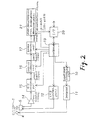
- Fig. 2 shows a configuration of the functions of a light-source controlling and sensor-signal processing device in the image reading apparatus having the above-described structure.
- a light-source controlling unit 10 controls the lighting time of the light source 4 by being controlled by a controller 19 which will be described later.
- a control signal from the light-source controlling unit 10 is outputted to an inverter 11, and lights the light source 4 for a selected time.
- a CCD control unit 12 generates a shift pulse in correspondence with the lighting timing of the light source 4, and controls the reading by the line sensor 5 in correspondence with the scanning speed of the carriage 3.
- An A/D converting unit 15 converts a light-quantity signal from the line sensor 5 inputted via an amplifier 14 into a digital signal, and delivers the same to a shading correction unit 16.
- the shading correction unit 16 corrects variations in the sensitivity for each photoelectric device included in the light-quantity signal from the line sensor 5.
- a gamma correction unit 17 converts the light-quantity signal corrected by the shading correction unit 16 into an image signal by using gamma functions.
- the image signal is 0 in the case of an ideal black, and assumes a value of 255 in the case of an ideal white.
- the controller 19 is constituted by a microcomputer comprising a CPU, a RAM, a ROM, and the like, is connected to an external image processor such as a personal computer via an interface 20, and controls the lighting time of the light source 4 and selects gamma functions in response to command signals from the personal computer.
- Reference numeral 21 denotes another processing unit for effecting various transformations, including color correction, edge enhancement, area enlargement/reduction, and the like with respect to the aforementioned image signals.
- the binarization processing which is the characteristic feature of the present invention is also effected by the processing unit 21.
- the user connects a personal computer (not shown) to the interface 20 of the image reading apparatus, places the original 8 on the original table 1, and instructs the execution of reading from the personal computer.
- the controller 19 causes the light source 4 to light up at each read-line position while consecutively moving the carriage 3 toward each read-line position. Consequently, a charge of an amount proportional to the reflectance of the original 8 is stored in the line sensor 5 at each read-line position.
- the controller 19 When the lighting time has elapsed at each read-line position, the controller 19 outputs a shift pulse to the CCD control unit 12 to thereby cause the charges stored in the line sensor 5 to be consecutively outputted to the amplifier 14, and at the same time moves the carriage 3 at a predetermined speed to a sub-scanning line subject to an ensuing reading.
- An output signal V from the line sensor 5 is amplified by the amplifier 14, is then converted into a digital signal by the analog/digital converting unit 15 and is outputted to the shading correction unit 16, and is then sent to the gamma correction unit 17 where the signal is converted into an image signal I by gamma functions.
- This image signal I is binarized by the other processing unit 21, and is finally outputted to the personal computer or displayed on a display via the interface 20.
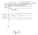
- This series of reading operation is schematically shown in Fig. 3.
- processing is carried out by consecutively reading blocks in the first line from the left in the main-scanning direction according to procedure 1, and binarized results are outputted.
- the operation proceeds to the reading operation of an ensuing line located one line below according to procedure 2, and processing is effected again from the left-end block to the right-end block, and binarized results are outputted.
- the reading of all the portions of an object image is finally completed.
- one block constituting a unit of processing is comprised of 16 pixels in the main-scanning direction, and one pixel in the sub-scanning direction.
- image signals of a plurality of lines are stored in advance, blocks each having a size of N x M pixels are generated, and processing is carried out consecutively.
- a first area to be referred to has 2 x 2 blocks, and a second area has 4 x 1 blocks, the sizes of these areas may be changed freely.
- the method for determining a threshold shall be a method based on a lookup table.
- Fig. 4 The form of processing an object image for explaining this embodiment is shown in Fig. 4.
- the main-scanning direction is set as X
- the sub-scanning direction is set as Y
- the origin for a processing start is set as the upper left end.
- the light source 4 of the carriage 3 is made to emit light on the line 0, and light-quantity signals are obtained by the line sensor 5.
- these light-quantity signals are divided into blocks (0, 0), (1, 0), (2, 0), ... each having 16 pixels, and the binarization processing of the respective blocks is performed consecutively.
- the respective image signals of 16 pixels (however, not necessarily 16 pixels at the rightmost image end) arranged in a horizontal row are consecutively binarized from left to right.
- the object pixel to which attention is focused is an i-th pixel (i is an integer greater than and equal to 0 and equal to and less than 15) in the block (K, L) to which attention is being focused.
- the binarization of the i-th pixel to which attention is focused is completed, the operation proceeds to the processing of an adjacent ensuing (i + 1)th pixel on the right, and the binarization processing is performed in the same way as the preceding i-th pixel.
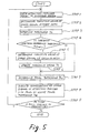
- Step 1 After the binarization processing of the (i-1)th pixel is finished, the object of processing is moved to the i-th pixel (Step 1).
- three reference blocks (K - 1, L - 1), (K, L-1), and (K - 1, L) and a portion of the attention-focused block (K, L) up to the attention-focused pixel, which are subject to control, are set as a first area.
- Maximum values are respectively determined for the four blocks, and a maximum value of the first area is determined from the four maximum values (Step 2).
- the maximum value means a value of the image signal closest to white in the block. Since all the image signals in the reference blocks (K - 1, L - 1), (K, L - 1), and (K - 1, L) are already known, the maximum values of the blocks are fixed.
- the maximum value can move as the attention-focused i-th pixel moves.
- the block (K, L - 1) and the attention-focused block (K, L) are set as the first area; when L is 0, the block (K - 1, L) and the attention-focused block (K, L) are set as the first area; and when both K and L are 0, only the attention-focused block (K, L) is set as the first area.
- a threshold Th is determined on the basis of a lookup table (hereafter referred to as the LUT) shown in Fig. 6.
- the LUT a lookup table
- the threshold is set to a value closer to black (a value closer to 0)
- the greater the maximum value generally, an image in which the background of the area is close to white
- the threshold is set to a value closer to white (a value closer to 255).
- Step 4 a comparison is made between this threshold Th and the threshold (hereafter referred to as the reference threshold Th(ref)) of a final pixel (hereafter referred to as the reference pixel) in the preceding block (K - 1, L). If Th is smaller, the operation proceeds to Step 5. If Th(ref) is less than or equal to Th, the operation jumps to Step 7. This measure is provided to ensure that an appropriate threshold is selected in correspondence with a location in the case of an original in which the tone of the background is not uniform and differs in some locations.
- the reference threshold need not necessarily be the threshold of a final pixel of the preceding block (K - 1, L), and may be another value, e.g., a maximum value of an image signal extracted from all the pixels of the preceding block.
- the reference threshold Th(ref) may be, for instance, a default value (e.g., 128), or a value determined from an immediately preceding sub-scanning line.
- K when K is 0, only the attention-focused block (K, L ) is set as the second area; when K is 1, the block (K - 1, L) and the attention-focused block (K, L) are set as the second area; and when K is 2, the blocks (K - 2, L) and (K - 1, L) and the attention-focused block (K, L) are set as the second area.
- a maximum value for the second area is determined in a method similar to the one used for determining the maximum value for the first area.
- the first area is determined in such a manner as to be provided with a plurality of blocks both in the main-scanning direction and in the sub-scanning direction
- the second area is determined in such a manner as to be provided with a plurality of blocks in the main-scanning line containing the attention-focused block.
- the method of determining the first and second areas is not confined to the same.
- the sizes of the first and second areas the larger the size of the character to be read, the size of the area should be made the larger.
- the sizes of the aforementioned two areas are determined on the assumption that characters having a size ranging from, for instance, several square millimeters to tens of square millimeters or thereabouts are read.
- the threshold is determined on the basis of the maximum value of the second area thus determined (Step 6).
- the table used at this time is the one shown in Fig. 6 used in Step 3, but a different table may of course be prepared.
- Th f (maximum value).
- Step 4 if, in Step 4, Th(ref) is less than or equal to Th, the threshold Th obtained at that time is determined as a final threshold Thd; meanwhile, if Th is less than Th(ref), the threshold Th obtained in the preceding Step 6 is determined as the final threshold Thd (Step 7). However, if Th is equal to Th(ref), the operation may go through Steps 5 and 6.
- the binarization of the image signal of the attention-focused i-th pixel is effected by using this final threshold Thd (Step 8).
- the value 1 is used, and if it is smaller, the value 0 is used.
- Step 9 the read processing of an ensuing sub-scanning line is started. If the sub-scanning line is not subject to processing (if there is no image signal), this binarization processing ends (Step 9).
- the binarization is performed with respect to each pixel for each sub-scanning line, and when that processing is finished, the operation proceeds to an ensuing sub-scanning line to effect processing.
- a result such as the one shown in Fig. 8(d) is obtained for an image shown in Fig. 8(a). This shows that the processed result is affected by the light and shade of the background, and that the subject information is read very clearly with high accuracy.
- thresholds are consecutively set with respect to the individual pixels in the attention-focused block.
- this second embodiment by referring to all the pixels in an initial attention-focused block, their maximum value is determined, and a maximum value of the first area is determined from four maximum values obtained by adding maximum values of the three reference blocks to the maximum value of the initial attention-focused block. Thereafter, processing is carried out in accordance with the flow starting with Step 3 shown in Fig. 5.
- the reference threshold in Step 4 can be set to be a value which is determined by the LUT from a maximum value among the values of all the pixels in the preceding block.
- the maximum value of the second area in Step 5 by first referring to all the pixels in the attention-focused block, their maximum value is determined, the maximum value of the second area is determined from among the four maximum values obtained by adding maximum values of the three reference blocks to the maximum value of the attention-focused block. Then, in Step 8, the individual pixels in the attention-focused block are not consecutively binarized, but when the final threshold with respect to the entire attention-focused block has been determined as described above, all the pixels in the block are binarized in a stroke. The binarized image obtained as a result is close to that of the first embodiment.
- an intermediate value or a minimum value is used instead of the maximum value of each block.
- the intermediate value means, for instance, a value obtained by adding together the maximum value and the minimum value of image signals in each block and dividing the same by 2.
- the fact that the intermediate value or the minimum value is used means that the characteristic signal of the image which is taken into consideration in determining the threshold is taken from not a white portion but a halftone between white and black, or a black portion.
- the threshold is set in correspondence with an intermediate value or a minimum value.
- the obtained result in terms of the reading accuracy in the case where an intermediate value was used, the obtained result was generally close to that in the case where a maximum value was used. In the case where a minimum value was used, however, the obtained result was liable to be inferior thereto.
- both a maximum value and a minimum value of each block is referred to in order to increase the accuracy of binarization.
- a minimum value of the first area is also determined at the same time.
- the method of determination is similar to that in the case of the maximum value.
- a table which takes into consideration both maximum values and minimum values, as shown in Fig. 7, is used in determining the threshold in Step 3 or 6.
- the threshold is determined by using only the maximum value as a parameter. Meanwhile, when the maximum value of the area is large, i.e., when the background of the subject area is close to white, the threshold is determined by taking into consideration both the maximum value and the minimum value. It is, of course, possible to use various other LUTs.
- the result is not much different from the result of the first embodiment.
- the reading accuracy can be expected to improve in the case of an image having white characters or colored characters in a black background.
- the image subject to reading is divided into mesh-like blocks, and the threshold for binarizing the individual pixels in these blocks is determined while referring to a characteristic value of an adjacent block (typically, a maximum value of the image signal). Accordingly, the binarization processing of the pixel to which attention is being focused can be executed while taking into consideration information on light and shade in its vicinity. Consequently, the object image can be read with high accuracy.
- the lookup table is used as the method of determining the threshold, if the cases of the threshold are classified into a greater number of values, the recognition accuracy can be improved. In that case, it goes without saying that the calculation efficiency can be improved if the dividing numerical value for the classification of the cases is set to be a multiple of 8 or 16.
- the present invention should not be confined to these embodiments, and can be implemented in various other forms without departing from its scope.
- the present invention can also be implemented in a copying machine, a facsimile communication system, or a system combining a computer and a scanner.
Landscapes
- Engineering & Computer Science (AREA)
- Multimedia (AREA)
- Signal Processing (AREA)
- Facsimile Image Signal Circuits (AREA)
- Image Input (AREA)
Applications Claiming Priority (3)
| Application Number | Priority Date | Filing Date | Title |
|---|---|---|---|
| JP31698694A JP3334385B2 (ja) | 1994-12-20 | 1994-12-20 | 画像読み取り装置および読み取り方法 |
| JP31698694 | 1994-12-20 | ||
| JP316986/94 | 1994-12-20 |
Publications (3)
| Publication Number | Publication Date |
|---|---|
| EP0719032A2 true EP0719032A2 (fr) | 1996-06-26 |
| EP0719032A3 EP0719032A3 (fr) | 1997-01-02 |
| EP0719032B1 EP0719032B1 (fr) | 2000-04-12 |
Family
ID=18083150
Family Applications (1)
| Application Number | Title | Priority Date | Filing Date |
|---|---|---|---|
| EP95307499A Expired - Lifetime EP0719032B1 (fr) | 1994-12-20 | 1995-10-20 | Méthode et dispositif pour lire une image |
Country Status (4)
| Country | Link |
|---|---|
| US (1) | US5796876A (fr) |
| EP (1) | EP0719032B1 (fr) |
| JP (1) | JP3334385B2 (fr) |
| DE (1) | DE69516255T2 (fr) |
Families Citing this family (13)
| Publication number | Priority date | Publication date | Assignee | Title |
|---|---|---|---|---|
| JPH09331453A (ja) * | 1996-06-13 | 1997-12-22 | Brother Ind Ltd | 画像読取装置および記憶媒体 |
| JP3669789B2 (ja) * | 1996-09-11 | 2005-07-13 | 富士写真フイルム株式会社 | 異常陰影候補の検出方法および装置 |
| EP0961218B1 (fr) | 1998-05-28 | 2004-03-24 | International Business Machines Corporation | Procédé de binarisation dans un système de reconnaissance de caractères |
| JP4224882B2 (ja) * | 1999-02-09 | 2009-02-18 | ソニー株式会社 | データ処理装置およびデータ処理方法 |
| DE10020178B4 (de) * | 1999-04-21 | 2005-01-13 | Ricoh Co., Ltd. | Apparat und Verfahren zur Bildbinärisierung sowie Apparat und Verfahren zur Bilderfassung |
| JP4018310B2 (ja) * | 1999-04-21 | 2007-12-05 | 株式会社リコー | 画像二値化装置、画像撮像装置、画像二値化方法、画像撮像方法およびその方法の各工程としてコンピュータを機能させるためのプログラムを記録したコンピュータ読取可能な記録媒体 |
| DE10066045B4 (de) * | 1999-04-21 | 2006-05-18 | Ricoh Co., Ltd. | Apparat und Verfahren zur Bildbinärisierung sowie Apparat und Verfahren zur Bilderfassung |
| US6496198B1 (en) | 1999-05-04 | 2002-12-17 | Canon Kabushiki Kaisha | Color editing system |
| US6494372B2 (en) * | 2000-04-04 | 2002-12-17 | International Business Machines Corporation | Self service terminal and method for processing transaction forms |
| US7301674B2 (en) * | 2002-10-31 | 2007-11-27 | Hewlett-Packard Development Company, L.P. | Translation of an input pixel value to an output pixel value |
| US7715656B2 (en) * | 2004-09-28 | 2010-05-11 | Qualcomm Incorporated | Magnification and pinching of two-dimensional images |
| JP4470958B2 (ja) * | 2007-05-01 | 2010-06-02 | 村田機械株式会社 | 画像処理装置 |
| JP4937417B1 (ja) * | 2011-06-14 | 2012-05-23 | 株式会社ナナオ | 文字領域画素判定装置またはその方法 |
Citations (1)
| Publication number | Priority date | Publication date | Assignee | Title |
|---|---|---|---|---|
| JPS5829674B2 (ja) | 1976-09-01 | 1983-06-24 | 三菱電機株式会社 | 2値化信号制御回路 |
Family Cites Families (12)
| Publication number | Priority date | Publication date | Assignee | Title |
|---|---|---|---|---|
| JPS5829674A (ja) * | 1981-08-14 | 1983-02-21 | Mitsubishi Heavy Ind Ltd | 輪転印刷機 |
| JPS5963884A (ja) * | 1982-10-05 | 1984-04-11 | Nec Corp | 画像読取装置 |
| US4709274A (en) * | 1983-08-29 | 1987-11-24 | Canon Kabushiki Kaisha | Image processing apparatus |
| US4593325A (en) * | 1984-08-20 | 1986-06-03 | The Mead Corporation | Adaptive threshold document duplication |
| JPS61290865A (ja) * | 1985-06-19 | 1986-12-20 | Ricoh Co Ltd | 中間調デジタル画像処理装置 |
| US5115478A (en) * | 1986-01-10 | 1992-05-19 | Minolta Camera Kabushiki Kaisha | Image reader |
| US4742400A (en) * | 1986-02-12 | 1988-05-03 | Ricoh Corporation | Digital image processing device for intermediate tone |
| DE3923449A1 (de) * | 1989-07-15 | 1991-01-24 | Philips Patentverwaltung | Verfahren zum bestimmen von kanten in bildern |
| EP0441614B1 (fr) * | 1990-02-08 | 1997-04-02 | Hewlett-Packard Company | Procédé et appareil pour l'établissement du niveau de seuil dans un balayeur de documents à mode binaire |
| US5214294A (en) * | 1991-04-19 | 1993-05-25 | Fuji Photo Film Co., Ltd. | Scan reading method including density measuring and edge detection |
| JPH05244419A (ja) * | 1991-11-25 | 1993-09-21 | Eastman Kodak Co | 2階調適応閾値を決定するシステムおよび方法 |
| EP0581971B1 (fr) * | 1992-02-25 | 1999-08-25 | Pfu Limited | Numeriseur d'image |
-
1994
- 1994-12-20 JP JP31698694A patent/JP3334385B2/ja not_active Expired - Fee Related
-
1995
- 1995-10-18 US US08/544,814 patent/US5796876A/en not_active Expired - Fee Related
- 1995-10-20 DE DE69516255T patent/DE69516255T2/de not_active Expired - Fee Related
- 1995-10-20 EP EP95307499A patent/EP0719032B1/fr not_active Expired - Lifetime
Patent Citations (1)
| Publication number | Priority date | Publication date | Assignee | Title |
|---|---|---|---|---|
| JPS5829674B2 (ja) | 1976-09-01 | 1983-06-24 | 三菱電機株式会社 | 2値化信号制御回路 |
Also Published As
| Publication number | Publication date |
|---|---|
| EP0719032A3 (fr) | 1997-01-02 |
| DE69516255T2 (de) | 2000-08-10 |
| DE69516255D1 (de) | 2000-05-18 |
| JP3334385B2 (ja) | 2002-10-15 |
| US5796876A (en) | 1998-08-18 |
| JPH08172532A (ja) | 1996-07-02 |
| EP0719032B1 (fr) | 2000-04-12 |
Similar Documents
| Publication | Publication Date | Title |
|---|---|---|
| US5677776A (en) | Image reader for processing an image of a document | |
| US5796876A (en) | Apparatus for reading image and method therefor | |
| US10356269B2 (en) | Image reading apparatus and original size detection method | |
| JP2721334B2 (ja) | 画像2値化処理装置 | |
| US5086486A (en) | Apparatus for reading a document and processing the image | |
| US5371610A (en) | Image data processing apparatus | |
| US5014332A (en) | Image reader | |
| JP3040896B2 (ja) | 画像処理装置 | |
| JP2008227625A (ja) | 画像処理装置、画像処理方法、画像処理プログラム、記録媒体 | |
| US5228099A (en) | Apparatus for reading a document and processing the image | |
| JP2009303164A (ja) | 画像読取装置及び画像読取装置の制御方法 | |
| US6055007A (en) | Image processing device and image reading device | |
| JP5910002B2 (ja) | 画像読み取り装置、原稿サイズ検出方法及び原稿サイズ検出プログラム | |
| JP2010010839A (ja) | 画像読取装置、その処理方法及びプログラム | |
| JPH05219370A (ja) | 画像処理装置 | |
| JP2888627B2 (ja) | 画像読み取り装置 | |
| JPH02218270A (ja) | 画像読取り装置における2値化処理方式 | |
| JP3234650B2 (ja) | 赤黒データ読み取り装置 | |
| JP2025118004A (ja) | 読取装置 | |
| JP2019176336A (ja) | 画像処理装置、画像送信装置、画像処理方法及び画像処理プログラム | |
| JPH0846786A (ja) | 画像形成装置 | |
| JPH0338782A (ja) | 原稿濃度検出装置 | |
| JPH08255224A (ja) | デジタル複写機 | |
| JPH0636553B2 (ja) | 画像処理装置 | |
| JPH0537770A (ja) | 画像処理装置 |
Legal Events
| Date | Code | Title | Description |
|---|---|---|---|
| PUAI | Public reference made under article 153(3) epc to a published international application that has entered the european phase |
Free format text: ORIGINAL CODE: 0009012 |
|
| AK | Designated contracting states |
Kind code of ref document: A2 Designated state(s): DE FR GB |
|
| PUAL | Search report despatched |
Free format text: ORIGINAL CODE: 0009013 |
|
| AK | Designated contracting states |
Kind code of ref document: A3 Designated state(s): DE FR GB |
|
| 17P | Request for examination filed |
Effective date: 19970612 |
|
| 17Q | First examination report despatched |
Effective date: 19981229 |
|
| GRAG | Despatch of communication of intention to grant |
Free format text: ORIGINAL CODE: EPIDOS AGRA |
|
| GRAG | Despatch of communication of intention to grant |
Free format text: ORIGINAL CODE: EPIDOS AGRA |
|
| GRAH | Despatch of communication of intention to grant a patent |
Free format text: ORIGINAL CODE: EPIDOS IGRA |
|
| GRAH | Despatch of communication of intention to grant a patent |
Free format text: ORIGINAL CODE: EPIDOS IGRA |
|
| GRAA | (expected) grant |
Free format text: ORIGINAL CODE: 0009210 |
|
| AK | Designated contracting states |
Kind code of ref document: B1 Designated state(s): DE FR GB |
|
| REF | Corresponds to: |
Ref document number: 69516255 Country of ref document: DE Date of ref document: 20000518 |
|
| ET | Fr: translation filed | ||
| PLBE | No opposition filed within time limit |
Free format text: ORIGINAL CODE: 0009261 |
|
| STAA | Information on the status of an ep patent application or granted ep patent |
Free format text: STATUS: NO OPPOSITION FILED WITHIN TIME LIMIT |
|
| 26N | No opposition filed | ||
| REG | Reference to a national code |
Ref country code: GB Ref legal event code: IF02 |
|
| PGFP | Annual fee paid to national office [announced via postgrant information from national office to epo] |
Ref country code: DE Payment date: 20071018 Year of fee payment: 13 |
|
| PGFP | Annual fee paid to national office [announced via postgrant information from national office to epo] |
Ref country code: GB Payment date: 20071017 Year of fee payment: 13 Ref country code: FR Payment date: 20071009 Year of fee payment: 13 |
|
| GBPC | Gb: european patent ceased through non-payment of renewal fee |
Effective date: 20081020 |
|
| REG | Reference to a national code |
Ref country code: FR Ref legal event code: ST Effective date: 20090630 |
|
| PG25 | Lapsed in a contracting state [announced via postgrant information from national office to epo] |
Ref country code: DE Free format text: LAPSE BECAUSE OF NON-PAYMENT OF DUE FEES Effective date: 20090501 |
|
| PG25 | Lapsed in a contracting state [announced via postgrant information from national office to epo] |
Ref country code: FR Free format text: LAPSE BECAUSE OF NON-PAYMENT OF DUE FEES Effective date: 20081031 |
|
| PG25 | Lapsed in a contracting state [announced via postgrant information from national office to epo] |
Ref country code: GB Free format text: LAPSE BECAUSE OF NON-PAYMENT OF DUE FEES Effective date: 20081020 |