EP0720043A2 - Barrillet d'objectifs - Google Patents
Barrillet d'objectifs Download PDFInfo
- Publication number
- EP0720043A2 EP0720043A2 EP95120556A EP95120556A EP0720043A2 EP 0720043 A2 EP0720043 A2 EP 0720043A2 EP 95120556 A EP95120556 A EP 95120556A EP 95120556 A EP95120556 A EP 95120556A EP 0720043 A2 EP0720043 A2 EP 0720043A2
- Authority
- EP
- European Patent Office
- Prior art keywords
- mode
- aspect ratio
- extender
- gear
- shrinker
- Prior art date
- Legal status (The legal status is an assumption and is not a legal conclusion. Google has not performed a legal analysis and makes no representation as to the accuracy of the status listed.)
- Granted
Links
Images












Classifications
-
- G—PHYSICS
- G03—PHOTOGRAPHY; CINEMATOGRAPHY; ANALOGOUS TECHNIQUES USING WAVES OTHER THAN OPTICAL WAVES; ELECTROGRAPHY; HOLOGRAPHY
- G03B—APPARATUS OR ARRANGEMENTS FOR TAKING PHOTOGRAPHS OR FOR PROJECTING OR VIEWING THEM; APPARATUS OR ARRANGEMENTS EMPLOYING ANALOGOUS TECHNIQUES USING WAVES OTHER THAN OPTICAL WAVES; ACCESSORIES THEREFOR
- G03B19/00—Cameras
- G03B19/02—Still-picture cameras
- G03B19/04—Roll-film cameras
- G03B19/07—Roll-film cameras having more than one objective
-
- H—ELECTRICITY
- H04—ELECTRIC COMMUNICATION TECHNIQUE
- H04N—PICTORIAL COMMUNICATION, e.g. TELEVISION
- H04N23/00—Cameras or camera modules comprising electronic image sensors; Control thereof
- H04N23/50—Constructional details
- H04N23/55—Optical parts specially adapted for electronic image sensors; Mounting thereof
Definitions
- This invention relates to a lens barrel applicable to an image pickup apparatus capable of changing an aspect ratio, and particularly to a lens barrel in which a converting lens unit for changing over the aspect ratio is adapted to be removably provided in a portion of a photo-taking system when for example, the aspect ratio of an effective image field is reversibly changed from 4:3 to 16:9.
- the width of length ratio the so-called aspect ratio of the effective image pickup surface (image field) of an ordinary television camera, a video camera or the like is 4:3.
- the EDTV system having the aspect ratio of image field of 16:9 is being put into practical use as the broadcasting system of the next generation. Therefore, recently, in order to cope with both of the ordinary TV system and the EDTV system of the aspect ratio 16:9, there have been proposed various cameras (image pickup apparatuses) which can selectively use the aspect ratio 16:9 and the aspect ratio 4:3.
- the deflection area of an electron beam is electrically changed over to thereby change the width to length ratio (the aspect ratio) while keeping the diagonal length of the image field.
- a solid state image pickup element such as a CCD element
- the diagonal length of the image field becomes short and therefore, an image obtained by a photo-taking lens cannot be effectively used, and this leads to the disadvantage that the diagonal angle of view becomes narrow or sensitivity is reduced. That is, supposing that only the aspect ratio is simply changed, there axises the problem that the angle of view varies on a monitor.
- the turret system is used for the changeover of the extender. Therefore, this system is very effective in the case of a large photo-taking lens like, for example, a lens for a studio camera.
- an objective lens applicable to an image pickup apparatus of which the size of the image pickup surface is changeable over between a first mode of a first aspect ratio and a second mode of a second aspect ratio has first optical means for extending the focal length of said objective lens, second optical means for shrinking the focal length of said objective lens, an operating member, and a transmitting mechanism for transmitting the operating force of said operating member to said first optical means under said first mode, and transmitting the operating force of said operating member to said first and second optical means under said second mode, and by the operation of said operating member, under said first mode, said first optical means is removably insertable into the optical path of said objective lens, and under said second mode, said first and second optical means are removably insertable into the optical path of said objective lens.
- Figure 1 is a cross-sectional view of a lens barrel according to an embodiment of the present invention.
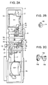
- Figures 2A, 2B and 2C are a side cross-sectional view and the like of the lens barrel according to an embodiment of the present invention (when the aspect ratio is 16:9).
- Figure 3 is a perspective view of the whole of a camera according to an embodiment of the present invention.
- Figure 4 is a cross-sectional view of the lens barrel according to an embodiment of the present invention.
- Figure 5 is a cross-sectional view of the lens barrel according to an embodiment of the present invention.
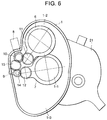
- Figure 6 is a cross-sectional view of the lens barrel according to an embodiment of the present invention.
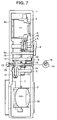
- Figure 7 is a side cross-sectional view of the lens barrel according to an embodiment of the present invention (when the aspect ratio is 4:3).
- Figure 8 is a cross-sectional view of a lens barrel according to an embodiment of the present invention.
- Figure 9 is a cross-sectional view of a lens barrel according to an embodiment of the present invention.
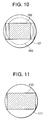
- Figure 10 shows an image circle at an aspect ratio of 4:3.
- Figure 11 shows an image circle at an aspect ratio of 16:9.
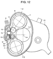
- Figure 12 is a cross-sectional view of a lens barrel according to another embodiment of the present invention.
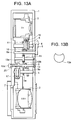
- Figures 13A and 13B are side cross-sectional views of the lens barrel according to another embodiment of the present invention.
- Figure 14 is a side cross-sectional view of a lens barrel according to another embodiment of the present invention.
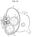
- Figure 15 is a cross-sectional view of the lens barrel according to another embodiment of the present invention.
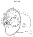
- Figure 16 is a cross-sectional view of a lens barrel according to another embodiment of the present invention.
- Figure 17 is a cross-sectional view of the lens barrel according to another embodiment of the present invention.
- Figure 18 is a cross-sectional view of a lens barrel according to still another embodiment of the present invention.
- Figures 19A and 19B are side cross-sectional views of the lens barrel according to still another embodiment of the present invention.
- Figure 20 is a cross-sectional view of the lens barrel according to still another embodiment of the present invention.
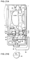
- Figures 21A and 21B are cross-sectional views of the lens barrel according to still another embodiment of the present invention.
- Figure 22 is a side cross-sectional view of the lens barrel according to still another embodiment of the present invention.
- Figure 23 is a cross-sectional view of a lens barrel according to still another embodiment of the present invention.
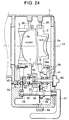
- Figure 24 is a side cross-sectional view of the lens barrel according to still another embodiment of the present invention.
- Figure 25 is a cross-sectional view of the lens barrel according to still another embodiment of the present invention.
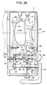
- Figure 26 is a side cross-sectional view of the lens barrel according to still another embodiment of the present invention.
- Figure 27 is a cross-sectional view of the lens barrel according to still another embodiment of the present invention.
- Figure 1 is a cross-sectional view of the essential portions of Embodiment 1 of the present invention
- Figures 2A, 2B and 2C are side views of the essential portions of Figure 1
- Figure 3 is a pictorial view of the essential portions of an image pickup apparatus according to the present invention
- Figures 4 and 5 are illustrations of Embodiment 1 of the present invention.
- Figures 2A, 2B and 2C show the case of an aspect ratio 16:9 and one-to-one magnification mode (mode A) (both of an extender and a shrinker are absent in an optical path).
- mode A both of an extender and a shrinker are absent in an optical path.
- Figure 4 shows the case of an aspect ratio 16:9 and two times mode (mode B) (the extender is inserted in the optical path).
- Figure 5 shows the case of an aspect ratio 4:3 and 2.427 times mode (mode D) (the extender is inserted in the optical path).
- Figure 6 shows the case of an aspect ratio 4:3 and one-to-one magnification mode (mode C) (the shrinker is inserted in the optical path).
- the reference numeral 1 designates a housing containing an interchangeable lens unit therein.
- the housing 1 contains therein an extender 2a for enlarging the focal length and a shrinker 3a for shrinking the focal length shown in Figure 7.
- the housing 1 is provided between a photo-taking lens body 26 having a zoom lens and a camera body 27 ( Figure 3).
- the reference numeral 28 denotes a photographer
- the reference numeral 29 designates the photographer's eyeballs.
- the reference numeral 1-1 denotes a photo-taking optical path area
- La designates the optical axis thereof.
- the reference numeral 1-2 denotes an upper retraction area
- the reference numeral 1-3 designates a lower retraction area.
- the reference numeral 2 denotes an extender barrel having an extender unit 2a.
- the extender is comprised of an enlarging system lens having two times as the photographing magnification and the focal length range of the whole system is varied to two times toward a longer one (two times mode).
- the reference numeral 3 designates a shrinker barrel holding a converting lens 3a to be inserted into an optical path correspondingly to the time when an image size (aspect ratio) is converted.
- the shrinker is comprised of a shrinking system lens having 0.824 time as the photographing magnification. Accordingly, in the mode A and mode C which will be described later, substantially the same angle of view is maintained in spite of the aspect ratio having been varied.
- the reference numeral 4 denotes a rotary shaft which corresponds to the center of rotation of the extender barrel 2.
- the reference numeral 5 designates a rotary shaft which corresponds to the center of rotation of the shrinker barrel 3.
- the reference numeral 6 denotes a sector which fixes the rotary shaft 4 and the extender barrel 2.
- the reference numeral 7 designates a sector which fixes the rotary shaft 5 and the shrinker barrel 3.
- the reference numeral 8 denotes a changeover lever as an operating member for selectively removably inserting the extender barrel 2 and the shrinker barrel 3 into the optical path.
- the reference character 8a designates a lever shaft on which the changeover lever 8 is mounted.
- the reference numeral 9 denotes a lever for changing over the mode from a mode of an aspect ratio (second aspect ratio) 4:3 to a mode of an aspect ratio (first aspect mode) 16:9 or conversely.
- the reference numeral 10 designates a gear fixedly mounted on the lever shaft 8a.
- the reference numeral 11 denotes a gear constituting an element of extender changeover means. The gear 11 is fixed to the sector 6 and is in meshing engagement with the gear 10.
- the reference numeral 12 designates a gear as shrinker changeover means. The gear 12 is fixed to the sector 7 and is in meshing engagement with a clutch gear 14.
- the clutch gear 14 constitutes an element of connecting means, is slidable in the axial direction of a shaft 13 and is rotatable with the rotation of the lever 9. That is, the clutch gear 14, as shown in Figure 2C, has a slot 14c in the central portion thereof, and a pin 13a fixed to the shaft 13 is engaged with the slot 14c so that the clutch gear may be slidable only in the axial direction.
- a gear 14b at the right of the clutch gear has a cut-away portion in a portion thereof and is adapted to be connected and disconnected with a stopper 18 which will be described later.
- the gear 14a of the clutch gear is normally in meshing engagement with the gear 12 and slides to thereby mesh with both of the gear 12 and an idler gear 15 and connect these two gears together.
- the idler gear 15 is normally in meshing engagement with the gear 10.
- the reference numeral 16 denotes a spring resiliently holding the extender barrel 2 and the sector 6.
- the reference numeral 17 designates a spring resiliently holding the shrinker barrel 3 and the sector 7.
- the reference numeral 18 denotes a stopper as connection releasing means provided in the housing 1. The stopper 18 regulates the meshing engagement between the gear 14 and the idler gear 15 and the releasing thereof.
- the reference numeral 19 designates a spring biasing the clutch gear 14 leftwardly as viewed in Figure 2A.
- the reference numeral 20 denotes a spring biasing the shaft 13 leftwardly as viewed in Figure 2A.
- the reference numeral 21 ( Figure 1) designates a driving grip provided sideways of the photo-taking lens 26.
- the conversion of the aspect ratio and the enlargement (magnification) of the zoom range are coped within a state in which one of the extender and the shrinker is removably inserted into a portion of the zoom lens (photo-taking system) 26, for example, the optical path of a relay lens or in a state in which none of the extender and the shrinker is inserted.
- the construction of the used states of the extender and the shrinker in each mode at this time is as shown in Table 1 below.
- Figures 1, 2A, 2B and 2C show a case where the aspect ratio is 16:9 and the whole system not using the extender is in mode A of one-to-one magnification (aspect ratio 16:9, one-to-one magnification mode).
- the extender barrel 2 and the shrinker barrel 3 are both disposed at positions retracted from the optical axis La.
- the changeover lever 8 When in this state, the changeover lever 8 is operated, the lever shaft 8a on which the changeover lever 8 is mounted is rotated and the gear 10 is also rotated. Since the gear 10 is in meshing engagement with the gear 11, the gear 11 is rotated to thereby rotate the sector 6. Thereby, as shown in Figure 4, the extender barrel 2 is disposed on the optical axis La. At this time, the mode becomes mode B (aspect ratio 16:9, two times mode) in which the aspect ratio is 16:9 and the focal length of the whole system has been enlarged to two times.
- mode B aspect ratio 16:9, two times mode
- the changeover lever 8 when conversely, the changeover lever 8 is returned, the same member is reversely rotated and the extender barrel 2 retracts from the optical axis La.
- the gear 14a of the clutch gear and the gear 15 provided on the shrinker barrel 3 side do not touch each other at all. Accordingly, the shrinker barrel 3 remains retracted from the optical path.
- the mode returns to the mode (aspect ratio 16:9, one-to-one magnification mode) in which the aspect ratio is 16:9 and the focal length range of the whole system is one-to-one magnification free of any variation.
- the present embodiment adopts a construction in which when the mode of the aspect ratio (first aspect ratio) 16:9 is selected, the shrinker is inhibited from entering and only the extender barrel 2 can be changed over by the changeover lever 8.
- the mode changeover lever 9 is rotated. Thereupon, immediately before the rotating operation of the lever 9 is terminated, the clutch gear 14 so far regulated by the stopper 18 comes out of engagement with the stopper 18 and is moved to the left of the shaft 13 as viewed in Figure 2A by the biasing force of the spring 19, and the gear 14a of the clutch gear comes into meshing engagement with the gear 15. Thereby, the extender barrel 2 and the shrinker barrel 3 are connected together.
- the mutual changeover between the mode B and the mode D is effected by electrical processing in the camera body with the extender 2a disposed in the optical path.
- the changeover to each mode is made easy by the construction in which: provision is made of the connecting means and connection releasing means which makes the operation of only changing over the shrinker and the extender by only one changeover operation of the operating means in accordance with the aspect ratio and which can be selected by the photographer; provision is made of the connecting means and connection releasing means which can effect the extender changeover operation and the connecting lens unit changeover operation at a time by the converting lens unit changeover operation; the center of the rotational movement during the changeover of the extender and the converting lens unit is divided and the retraction location of the lens unit from the optical axis is secured at a position whereat the photographer can confirm the index and a numerical value corresponding thereto; some of the gears change their positions in parallelism to the rotary shaft to thereby come out of meshing engagement and effect connection and the releasing of the connection; and provision is made of the shaft and the gear movable in the axial direction and transmitting only the rotational force and weighted by the spring and having
- FIG 8 is a schematic view of the essential portions of Embodiment 2 of the present invention.
- This embodiment as compared with Embodiment 1, is one in which the disposition of the barrels is vertically reversed (in this state, one-to-one magnification of an aspect ratio 4:3). That is, design is made such that the extender barrel 2 is retracted downwardly (the area 1-3) and the shrinker barrel 3 is retracted upwardly (the area 1-2).
- the reference numerals in this figure designate the same parts as those in Embodiment 1.
- the reference numeral 30 designates a gear corresponding to the gear 14 in Embodiment 1 and movable in the thrust direction
- the reference numeral 31 denotes a gear corresponding to the gear 10 and fixed to the extender changeover lever
- the reference numeral 32 designates an idler gear which is normally in meshing engagement with the gear 11 and the gear 31.
- the operation and the movement of the barrels are the same as those in Embodiment 1, and the internal mechanism is also the same as that in Embodiment 1 except the position of the idler and therefore, detailed description of the operation need not be made.
- the disposition of the barrels can be done anyway, depending on the positional relation of the idler gear.
- FIG 9 is a schematic view of the essential portions of Embodiment 3 of the present invention.
- This embodiment as compared with Embodiment 2 of Figure 8, is one in which the operating system is vertically reversed (in this state, one-to-one magnification of an aspect ratio 4:3).
- the reference numerals in this embodiment designates the same parts as those in Embodiments 1 and 2.
- the reference numeral 33 denotes an idler gear corresponding to the idler gear 15 in Embodiment 1
- the reference numeral 34 designates a gear corresponding to the gear 10 and fixed to the extender changeover lever.
- the magnification of the extender has been described with respect to the case of two times, but may be any other magnification.
- a vertical portion of the image field is not used, but the area of 16:9 of the central portion may be used, or in such case, the magnification of the shrinker may be changed to 0.917 time and may be made to correspond thereto.
- a shrinker magnification corresponding thereto may likewise be adopted and may be made to correspond thereto.
- the photo-taking system having the converting lens (shrinker) for the changeover of the aspect ratio and the extender
- an image pickup apparatus capable of changing over the aspect ratio in which a driving mechanism for effecting the removable insertion of both lenses into the optical path is appropriately set, whereby irrespective of the use or non-use of the shrinker, by only the operation of removably inserting the extender into the optical path, photographing can be effected easily at one-to-one magnification or a different magnification (focal length range).
- the present invention can cope with a camera with the aspect ratio changeover function which enables the quick extender operation by the operation of the changeover lever similar to that in the prior art to be performed without giving a feeling of physical disorder to a photographer accustomed to the photographing operation of a zoom lens for the conventional handy camera with an extender.
- the photographer after he has once selected an aspect ratio, can be conscious of only the selection of one-to-one magnification and the extender as before and therefore, these makes it unnecessary for the photographer to newly learn to use the new function of changing over the aspect ratio, and can effectively prevent the eclipse of the photographed image which is a mistake absolutely unallowable in photographing.
- the reference character 5a designates a small gear as an element of converting lens changeover means.
- the small gear 5a is fixed to the rotary shaft 5.
- the reference character 5b denotes a large gear as an element of the converting lens changeover means.
- the large gear 5b is fixed to the rotary shaft 5.
- the reference numeral 13 designates a shaft gear constituting an element of connecting means and fixed to the lever 9.
- a large gear 13a and a small gear 13b are secured to the shaft 13c of the shaft gear 13.
- the small gear 5a, the large gear 5b and the shaft gear 13 together constitute an element of a speed reducing mechanism.
- the gear 13a as shown in Figure 13B, has a cut-away portion in a portion thereof, and this cut-away portion is in such relationship as not to mesh with the gear 15 in the case of a mode of 16:9.
- the shaft 13c is slidable in the axial direction thereof and is rotatable with the rotation of the lever 9.
- the shaft 13c is such that by its sliding, the large gear 13a meshes with the idler gear 15 and the small gear 5a ( Figures 13A and 13B) or the small gear 13b meshes with the large gear 5b ( Figure 14).
- the idler gear 15 is normally in meshing engagement with the gear 10.
- the shaft 13 is first pressed and slidden by fingers against the spring 20 to thereby bring the small gear 13a into meshing engagement with the gear 5b. Subsequently, the lever 9 is rotated to thereby insert the shrinker 3 into the optical path (the mode C). By releasing the fingers, the shaft slides leftwardly and now the gear 13a comes into meshing engagement with the gear 15 and thus, the rotative operation of the operating lever 8 is transmitted to the shrinker 3.
- the mode is first set to the mode C, whereafter the shaft 13c is pressed by fingers and the gear 13b is brought into meshing engagement with the gear 5b, whereafter the lever 8 is rotated to its original position, whereupon the shrinker is retracted from the optical axis La. By releasing the fingers, the original state is restored.
- the diameter of the gear 13b of the gears meshing with each other during the changeover of the aspect ratio is made smaller than the diameter of the gear 5a, whereby the operating force required to removably insert the shrinker can be made small and the operability is successfully improved.
- Figure 18 is a cross-sectional view of the essential portions of the present embodiment
- Figures 19A and 19B are side views of the essential portions of Figure 18, and
- Figures 20 to 22 are illustrations of the present embodiment.
- Figures 19A and 19B show the case of the aspect ratio 16:9 and one-to-one magnification mode (both of the extender and the shrinker are absent in the optical path).
- Figure 20 shows the case of the aspect ratio 16:9 and two times mode (the extender is inserted in the optical path).
- Figures 21A and 21B show the case of the aspect ratio 4:3 and 2.427 times mode (the extender is inserted in the optical path).
- Figure 22 shows the case of the aspect ratio 4:3 and one-to-one magnification mode (the shrinker is inserted in the optical path).
- the reference numeral 34 designates a rotary shaft which corresponds to the center of rotation of the extender barrel 2.
- the reference numeral 35 denotes a rotary shaft which corresponds to the center of rotation of the shrinker barrel 3.
- the reference numeral 6 designates a sector which holds the rotary shaft 34 and the extender lens 2.
- the reference numeral 7 denotes a sector which holds the rotary shaft 35 and the shrinker lens 3.
- the reference numeral 38 designates a changeover lever as an operating member which selectively removably mounts the extender lens 2 and the shrinker lens 3 in the optical path.
- the reference numeral 39 denotes a lever shaft on which the changeover lever 38 is mounted.
- the reference numeral 30 designates a changeover knob as an element of connection releasing means and aspect ratio setting means.
- the changeover knob 30 is operated with the changeover from the mode of the aspect ratio (second aspect ratio) 4:3 to the mode of the aspect ratio (first aspect ratio) 16:9.
- the reference numeral 31 denotes a gear as extender changeover means.
- the gear 31 is fixed to the sector 6 and in Figure 18, it is in meshing engagement with a clutch gear (connecting means) 33.
- the reference numeral 32 designates a gear as converting lens changeover means.
- the gear 32 is fixed to the sector 7 and is capable of meshing with the clutch gear 33.
- the clutch gear 33 is slidable in the axial direction of the lever shaft 39 and rotatable with the rotation of the lever shaft 39.
- the clutch gear 33 slides to thereby mesh with only the gear 31 or with both of the gear 31 and the gear 32.
- the reference numeral 34 denotes a pin which transmits the rotation of the lever shaft 39 to the clutch gear 33.
- the reference numeral 35 designates a stopper which holds the sector 6 for holding the extender barrel 2 on the optical axis.
- the reference numeral 36 denotes a stopper which holds the sector 7 for holding the shrinker barrel 3 on the optical axis.
- the reference numeral 37 designates a stopper which holds the sector 6 in a position wherein the extender barrel 2 is retracted from the optical axis.
- the reference numeral 38 denotes a stopper which holds the sector 7 in a position wherein the shrinker barrel 3 is retracted from the optical axis La of the photo-taking system.
- the reference numeral 41 designates a spring which resiliently holds the extender barrel 2 and the sector 6.
- the reference numeral 40 denotes a spring which resiliently holds the shrinker barrel 3 and the sector 7.
- the shrinker barrel 3 is always in a state retracted from the optical axis La.
- the extender changeover lever 38 being operated, only the extender barrel 2 is removably inserted onto the optical axis to thereby vary the focal length range of the whole system to one-to-one magnification (one-to-one magnification mode) and two times (two times mode).
- the extender changeover means 31 and the shrinker changeover means 32 are connected together by the connecting means 33 which is a clutch gear so that one of the shrinker barrel 3 and the extender barrel 2 may be disposed on the optical axis La without fail by one operation of the operating member 38. That is, the shrinker barrel 3 and the extender barrel 2 are connected together by the clutch gear 33 so as to be moved at a time by one operation of the changeover lever 38.
- Figures 18, 19A and 19B show cases where the aspect ratio is 16:9 and the whole system not using the extender is at one-to-one magnification (the aspect ratio 16:9, one-to-one magnification mode).
- the extender barrel 2 and the shrinker barrel 3 are both disposed at positions retracted from the optical axis La.
- the changeover lever 38 When in this state, the changeover lever 38 is operated, the lever shaft 39 on which the changeover lever 38 is mounted is rotated and the clutch gear 33 is also rotated therewith through the pin 34. Since the clutch gear 33 is in meshing engagement with the gear 31, the gear 31 is rotated to thereby rotate the sector 6. Thereby, as shown in Figure 20, the extender barrel 2 is disposed on the optical axis La. At this time, the mode becomes a mode in which the aspect ratio is 16:9 and the focal length range of the whole system has been enlarged to two times (the aspect ratio 16:9, two times mode).
- the changeover lever 38 is returned to its original position, the same member is reversely rotated to thereby retract the extender barrel 2 from the optical axis La.
- the clutch gear 33 does not at all touch the gear 32 provided on the shrinker barrel 3 side and accordingly, the shrinker barrel 3 remains retracted from the optical path.
- the mode becomes a mode in which the aspect ratio is 16:9 and the focal length range of the whole system is unchanged, i.e., one-to-one magnification (the aspect ratio 16:9, one-to-one magnification mode).
- the aspect ratio (first aspect ratio) 16:9 mode when the aspect ratio (first aspect ratio) 16:9 mode is selected, only the extender lens is changed over by the changeover lever 38.
- mode changeover is effected by the aspect ratio setting means 30 with the extender 2a disposed on the optical axis La and therefore, the changeover lever 38 is once operated to thereby dispose the extender barrel 2 on the optical axis La.
- the changeover knob 30 is rotated to effect mode changeover and the clutch gear 33 is pushed leftwardly as viewed in Figure 19A by a projection 30a provided integrally with the changeover knob 30.
- the clutch gear 33 slides on the lever shaft 39 and is fixed at a position in which it meshes with the gear 32 disposed in advance so as to mesh with the clutch gear 33.
- the changeover lever 38 is in the position of extender ON and therefore, when it is returned to its original position, the extender barrel 2 is retracted from the optical axis by the transmission of the rotation of the clutch gear 33 and the gear 31 as in the case of the aspect ratio 16:9 mode.
- the rotation is likewise transmitted to another gear 32 with which the clutch gear 33 is in meshing engagement, and the sector 7 is rotated about the rotary shaft 35 through the gear 32, and the shrinker barrel 3 becomes operatively associated with the extender barrel 2, whereby the extender barrel 2 is moved toward the optical axis conversely to being retracted from the optical axis, and becomes positioned on the optical axis.
- the angles by which the sector 6 and the sector 7 are rotatable are substantially the same and the speed reduction ratios of the clutch gear 33 and the gear 31 and of the clutch gear 33 and the gear 32 are the same.
- the meshing engagement among the gears 31, 32 and 33 is provided with a play sufficient to absorb the irregularity of the angle of rotation of each sector in the manufacture thereof. Therefore, design is made such that the sector 7 reliably strikes against the stopper 38 when the stopper 35 for positioning the extender barrel 2 at a position on the optical axis La is regulating the rotation of the sector 6.
- design is made such that the sector 6 reliably strikes against the stopper 7 when the stopper 36 for positioning the shrinker barrel 3 at a position on the optical axis La is regulating the rotation of the sector 7.
- the changeover knob 30 is rotated, whereafter the changeover lever 38 is operated, whereby the extender barrel 2 may be retracted from the optical axis and at the same time, the shrinker barrel 3 may be disposed on the optical axis.
- the changeover lever 38 is operated, whereby the extender barrel 2 may be retracted from the optical axis and at the same time, the shrinker barrel 3 may be disposed on the optical axis.
- the shrinker barrel 3 and the extender barrel 2 become removably inserted in operatively associated relationship with each other, and after a mode has once been set, as in the case of the aspect ratio 16:9, the extender operation is made possible by only the operation of the changeover lever 38, like the prior-art photo-taking lens which does not constitute a shrinker.
- the mode changeover knob 30 is again rotated, that is, the connection of the connecting means 33 is released to return it to its original position, whereupon photographing at the aspect ratio 16:9 again becomes possible.
- Figure 25 shows the case of the aspect ratio 16:9, one-to-one magnification mode (neither of the extender 2a and the shrinker (converting lens) 3a is present in the optical path).
- Figures 23 and 24 show the case of the aspect ratio 16:9, two times mode (the extender is inserted in the optical path).
- Figures 26 and 27 show the case of the aspect ratio 4:3, one-to-one magnification mode (the shrinker is inserted in the optical path).
- the reference numeral 54 designates a rotary shaft which corresponds to the center of rotation of the extender barrel 2 and of the shrinker barrel 3.
- the reference numeral 6 denotes a sector which fixes the rotary shaft 54 and the extender barrel 2.
- the reference numeral 7 designates a sector which fixes the rotary shaft 54 and the shrinker barrel 3.
- the reference numeral 57 denotes a changeover lever as an operating member on which the extender barrel 2 and the shrinker barrel 3 are mounted for selective removable insertion into the optical path.
- the reference numeral 58 designates a lever shaft on which the changeover lever 57 is mounted.
- the lever shaft 58 has a gear 58a thereon.
- the reference numeral 59 denotes a gear member fixed to the rotary shaft 54.
- a gear 59a provided on the outer periphery of the gear member 59 is shown as being in meshing engagement with the gear 58a on the lever shaft 58 in Figures 23 and 24.
- the rotary shaft 54, the sector 6 and the gear member 59 together constitute an element of extender changeover means.
- the rotary shaft 54, the sector 7, etc. together constitute an element of converting lens changeover means.
- the reference numeral 60 designates a clutch knob.
- the reference numeral 61 denotes a connecting pin which connects a clutch body 62 and the clutch knob 60 together.
- the clutch body 62 is operatively associated with the rotation of the clutch knob 60 and the connecting pin 61 and is rotatable about the rotary shaft 54.
- the reference numeral 63 designates a spring which biases the clutch body 62 toward the optical axis La.
- the reference numeral 64 denotes a clutch pin fixed to the clutch body 62.
- the clutch pin 64 slides in the direction of the optical axis to thereby effect the connection thereof to the gear member 59 and the release of the connection.
- the reference numeral 65 designates a clutch pin fixed to the clutch body 62 and connected to the sector 7.
- the reference numeral 68 denotes a mode fixing switch
- the reference numeral 69 designates a mode fixing plate which is fixed to the mode fixing switch 68 and prevents the connection between the clutch pin 64 and the gear member 59.
- the mode fixing switch 68, the clutch knob 60 and the clutch body 62 together constitute an element of mode changeover means.
- the focal length will extend toward the telephoto side as previously described and therefore, a hindrance will occur in the photographing at a wide angle.
- the shrinker is constructed and this problem is solved, it will be possible to utilize this nature as in the present embodiment and utilize an extender of apparently low magnification as being inserted.
- the apparent magnification of the extender is 1.214 times which is an inverse number of the magnification of the shrinker.
- the shrinker barrel 3 when a mode in which the aspect ratio is 16:9 (the aspect ratio 16:9 mode) is set by aspect ratio setting means (not shown) on the camera body side, the shrinker barrel 3 is always in its retracted state from the optical axis La.
- the changeover lever 57 is operated to thereby removably insert only the extender barrel 2 onto the optical axis and vary the focal length range of the whole system to the one-to-one magnification (one-to-one magnification mode) of Figure 25 and the two times (two times mode) of Figure 23. Also, in the case of the mode in which the aspect ratio is 4:3 (the aspect ratio 4:3 mode), by the operation of the changeover lever 57, the shrinker barrel 3 or the extender barrel 2 may be positioned on the optical axis or both of them may be positioned off the optical axis. That is, by the operation of the changeover lever 57, their positions are changed to those of Figures 23, 25 and 27.
- Figures 23 and 24 show a case where the aspect ratio is 16:9, the extender is used and the whole system is at two times (the aspect ratio 16:9, two times mode).
- the extender barrel 2 is disposed on the optical axis and the shrinker barrel 3 is disposed in a position retracted from the optical axis La.
- the changeover lever 57 When in this state, the changeover lever 57 is operated, the lever shaft 58 on which the changeover lever 57 is mounted is rotated and the gear 59a is also rotated therewith through the gear 58a. Since the gear member 59 is fixed to the sector 6, it rotates the sector 6. Thereby, as shown in Figure 25, the extender barrel 2 is retracted from the optical axis La. At this, the mode becomes a mode in which the aspect ratio is 16:9 and the focal length range of the whole system is one-to-one magnification (the aspect ratio 16:9, one-to-one magnification mode).
- the changeover lever 57 When conversely, the changeover lever 57 is returned to its original position, the same member is reversely rotated and the extender barrel 2 is positioned on the optical axis La.
- the clutch pin 64 provided on the clutch body 62 operatively associated with the shrinker barrel 3 side is prevented from being connected to the gear member 59 by the mode fixing plate 69. Accordingly, the shrinker barrel 3 remains retracted from the optical path.
- the mode becomes a mode in which the aspect ratio is 16:9 and the focal length range of the whole system is two times (the aspect ratio 16:9, two times mode).
- the operation of the extender is effected by only the changeover operation of the changeover lever 57 as in the prior-art photo-taking lens which does not constitute a shrinker.
- the mode fixing switch 58 is released on the lens side and the mode fixing plate 69 is slidden and retracted.
- the clutch knob 60 is then rotated to thereby fit the clutch pin 64 biased by the spring 63 into an aperture formed in the gear member 59.
- connection between the converting lens changeover means and the extender changeover means or the operating member is effected (when the aspect ratio is 16:9, the clutch knob 60 is slidden in the direction of the optical axis against the force of the spring 63 to thereby release the connection between the clutch pin 64 and the gear member 59, and then the mode fixing switch 68 is changed over to thereby release the connection between the converting lens changeover means and the extender changeover means.
- the changeover lever 57 is then further rotated from the state of Figure 25.
- the lever shaft 58 is rotated and the clutch body 62 and the sector 7 are rotated about the rotary shaft 54 through the gear 58a and the clutch pin 64, whereby the shrinker barrel 3 is disposed on the optical axis.
- the shrinker barrel 3 is positioned on the optical axis.
- the mode is a one-to-one magnification mode of the aspect ratio 4:3.
- the mode fixing switch 68 If the mode fixing switch 68 is changed over by a procedure converse to the above-described operation, the mode can be returned to the mode of the aspect ratio 16:9.
- design is made such that the changeover shaft of the changeover lever 57 is left to the optical axis as viewed from the camera side, but alternatively, design may be made such that the changeover shaft is right to the optical axis. Also, design may be made such that the shrinker barrel 3 is retracted upwardly and the extender barrel 2 is retracted downwardly.
- the magnification of the extender has been described as two times, but the extender may be designed at any other magnification.
- the image field of the aspect ratio 16:9 which is an area thereof is to be photographed
- a vertical portion of the image field is not used, but the central area of the aspect ratio 16:9 may be used or in this case, the magnification of the shrinker may be changed to 0.917 time, thereby coping with it.
- a shrinker magnification conforming thereto may likewise be adopted to thereby cope with it.
- an image pickup apparatus capable of changing over the aspect ratio
- a photo-taking system having a converting lens (shrinker) and an extender for the changeover of the aspect ratio
- a driving mechanism for effecting the removable insertion of the both lenses into the optical path is appropriately set, whereby the extender or the shrinker may easily or may not be positioned in the optical path and photographing can be effected easily at a predetermined aspect ratio and one-to-one magnification or different magnifications (focal length range).
- the present invention can cope with a camera with the aspect ratio changeover function which does not give a feeling of physical disorder to any photographer accustomed to the photographing operation of a zoom lens for a prior-art handy camera with an extender and which enables a quick extender operation by the operation of a changeover lever similar to that of the prior art.
- the extender function of the order of 1.2 times can be realized without newly adding any optical system besides the shrinker prepared for one-to-one magnification.
- the use of an extender of two times reduces the quantity of light to half and therefore it is difficult to enlarge the focal length, it becomes possible to minimize the reduction in the quantity of light and make the focal length on the telephoto side equal to that of a lens ranking above by one class, and an extender of a little over 2.4 times can be provided and the range of selection can be more widened for the photographer.
- An objective lens for application to an image apparatus of which the size of the image pickup surface is changeable over between a first mode of a first aspect ratio and a second mode of a second aspect ratio has first optical member for extending the focal length of the objective lens, second optical member for shrinking the focal length of the objective lens, an operating member, and a transmitting mechanism for transmitting the operating force of the operating member to the first optical member under the first mode, and transmitting the operating force to the first and second optical member under the second mode, and by the operation of the operating member, under the first mode, the first optical member is removably insertable into the optical path of the objective lens, and under the second mode, the first and second optical member are removably insertable into the optical path of the objective lens.
Landscapes
- Engineering & Computer Science (AREA)
- Multimedia (AREA)
- Signal Processing (AREA)
- Physics & Mathematics (AREA)
- General Physics & Mathematics (AREA)
- Lens Barrels (AREA)
- Structure And Mechanism Of Cameras (AREA)
Applications Claiming Priority (12)
| Application Number | Priority Date | Filing Date | Title |
|---|---|---|---|
| JP339057/94 | 1994-12-28 | ||
| JP33905894A JP3727966B2 (ja) | 1994-12-28 | 1994-12-28 | アスペクト比切り換え可能な撮像装置 |
| JP33905794A JP3647073B2 (ja) | 1994-12-28 | 1994-12-28 | アスペクト比切り換え可能な撮像装置 |
| JP33905794 | 1994-12-28 | ||
| JP339058/94 | 1994-12-28 | ||
| JP33905894 | 1994-12-28 | ||
| JP26059/95 | 1995-01-20 | ||
| JP2605995 | 1995-01-20 | ||
| JP7026059A JPH08205011A (ja) | 1995-01-20 | 1995-01-20 | アスペクト比切り換え可能な撮像装置 |
| JP7030138A JPH08205006A (ja) | 1995-01-25 | 1995-01-25 | アスペクト比切り換え可能な撮像装置 |
| JP30138/95 | 1995-01-25 | ||
| JP3013895 | 1995-01-25 |
Publications (3)
| Publication Number | Publication Date |
|---|---|
| EP0720043A2 true EP0720043A2 (fr) | 1996-07-03 |
| EP0720043A3 EP0720043A3 (fr) | 1997-04-16 |
| EP0720043B1 EP0720043B1 (fr) | 2002-10-09 |
Family
ID=27458422
Family Applications (1)
| Application Number | Title | Priority Date | Filing Date |
|---|---|---|---|
| EP95120556A Expired - Lifetime EP0720043B1 (fr) | 1994-12-28 | 1995-12-27 | Barillet d'objectifs |
Country Status (3)
| Country | Link |
|---|---|
| US (1) | US5696634A (fr) |
| EP (1) | EP0720043B1 (fr) |
| DE (1) | DE69528514T2 (fr) |
Cited By (1)
| Publication number | Priority date | Publication date | Assignee | Title |
|---|---|---|---|---|
| EP0841583A1 (fr) * | 1996-11-08 | 1998-05-13 | Samuelson Film Service London Limited | Adapteur optique |
Families Citing this family (3)
| Publication number | Priority date | Publication date | Assignee | Title |
|---|---|---|---|---|
| JP3867389B2 (ja) * | 1998-03-05 | 2007-01-10 | フジノン株式会社 | カメラのエクステンダー装置 |
| JP4277422B2 (ja) * | 2000-05-19 | 2009-06-10 | フジノン株式会社 | 光学装置 |
| JP4461116B2 (ja) * | 2006-04-12 | 2010-05-12 | セイコープレシジョン株式会社 | レンズ駆動装置 |
Family Cites Families (16)
| Publication number | Priority date | Publication date | Assignee | Title |
|---|---|---|---|---|
| US3185061A (en) * | 1962-08-13 | 1965-05-25 | Leonard F Westphalen | Multifocal camera |
| US3817600A (en) * | 1971-06-14 | 1974-06-18 | Ponder & Best | Zoom lens having close-up focusing mode of operation |
| AT343937B (de) * | 1975-08-06 | 1978-06-26 | Eumig | Pankratisches objektiv |
| DE7530280U (de) * | 1975-09-25 | 1976-01-22 | Agfa-Gevaert Ag, 5090 Leverkusen | Fotografische kamera mit mehreren objektiven |
| US4669848A (en) * | 1983-12-07 | 1987-06-02 | Nippon Kogaku K. K. | Camera having partially retractable taking optical system |
| US4865434A (en) * | 1984-10-01 | 1989-09-12 | Canon Kabushiki Kaisha | Zoom lens capable of selecting a focal length beyond a standard focal length range |
| US4774536A (en) * | 1986-01-10 | 1988-09-27 | Minolta Camera Kabushiki Kaisha | Photographic camera |
| US5291233A (en) * | 1989-01-30 | 1994-03-01 | Minolta Camera Kabushiki Kaisha | Camera having an auto zoom function |
| JPH03177805A (ja) * | 1989-12-05 | 1991-08-01 | Canon Inc | ズームレンズ鏡筒 |
| JPH04125607A (ja) * | 1990-09-18 | 1992-04-27 | Canon Inc | 光学機器 |
| US5258799A (en) * | 1991-03-12 | 1993-11-02 | Minolta Camera Kabushiki Kaisha | Auto focus camera with pseudo focal length mode |
| JP2817754B2 (ja) * | 1992-07-30 | 1998-10-30 | 富士写真フイルム株式会社 | カメラの光学部材の切換装置 |
| JP3581376B2 (ja) * | 1993-02-01 | 2004-10-27 | キヤノン株式会社 | ズームレンズシステム、あるいは光学機器 |
| US5794090A (en) * | 1993-02-01 | 1998-08-11 | Canon Kabushiki Kaisha | Zoom lens |
| JPH06303469A (ja) * | 1993-02-19 | 1994-10-28 | Fuji Photo Optical Co Ltd | テレビジョンカメラ用レンズ装置 |
| US5473404A (en) * | 1994-03-10 | 1995-12-05 | Eastman Kodak Company | Zoom camera having electronic exposure control |
-
1995
- 1995-12-27 DE DE69528514T patent/DE69528514T2/de not_active Expired - Lifetime
- 1995-12-27 US US08/580,277 patent/US5696634A/en not_active Expired - Lifetime
- 1995-12-27 EP EP95120556A patent/EP0720043B1/fr not_active Expired - Lifetime
Cited By (1)
| Publication number | Priority date | Publication date | Assignee | Title |
|---|---|---|---|---|
| EP0841583A1 (fr) * | 1996-11-08 | 1998-05-13 | Samuelson Film Service London Limited | Adapteur optique |
Also Published As
| Publication number | Publication date |
|---|---|
| EP0720043B1 (fr) | 2002-10-09 |
| US5696634A (en) | 1997-12-09 |
| DE69528514D1 (de) | 2002-11-14 |
| EP0720043A3 (fr) | 1997-04-16 |
| DE69528514T2 (de) | 2003-06-26 |
Similar Documents
| Publication | Publication Date | Title |
|---|---|---|
| US5475457A (en) | Focal point adjusting device for zoom lens | |
| US4945372A (en) | Camera | |
| US8564895B2 (en) | Lens barrel, an imaging device, a optical system retaining method and a manufacturing method | |
| JPH05188505A (ja) | ズームカメラ | |
| EP0720043B1 (fr) | Barillet d'objectifs | |
| US7277237B2 (en) | AF control apparatus for zoom lens system | |
| JP4204890B2 (ja) | 映画撮影用カメラの対物レンズ | |
| EP1287402A2 (fr) | Systeme optique pour faire tourner des images prises par une camera autour de l'axe optique | |
| JP3727966B2 (ja) | アスペクト比切り換え可能な撮像装置 | |
| JP3647073B2 (ja) | アスペクト比切り換え可能な撮像装置 | |
| US6647207B2 (en) | Parallax correction for close focus | |
| JPH08195902A (ja) | アスペクト比切り換え可能な撮像装置 | |
| JP2770071B2 (ja) | 光学機器用レンズ鏡胴 | |
| JP4488278B2 (ja) | 鏡筒駆動機構 | |
| US12429677B2 (en) | Optical apparatus and image-capturing apparatus | |
| JPH08205006A (ja) | アスペクト比切り換え可能な撮像装置 | |
| JPH01207731A (ja) | カメラ | |
| JP4628015B2 (ja) | ズームレンズにおけるaf制御装置 | |
| JPH08205011A (ja) | アスペクト比切り換え可能な撮像装置 | |
| JP2956368B2 (ja) | レンズバリアを有したカメラ | |
| JPH0630309A (ja) | 人物・書画兼用カメラ | |
| JPH06245117A (ja) | 人物・書画兼用テレビジョンカメラ | |
| JP4555606B2 (ja) | ズームレンズにおけるaf制御装置 | |
| JPS5915227A (ja) | カメラの焦点距離可変装置 | |
| JP2001290208A (ja) | カメラ |
Legal Events
| Date | Code | Title | Description |
|---|---|---|---|
| PUAI | Public reference made under article 153(3) epc to a published international application that has entered the european phase |
Free format text: ORIGINAL CODE: 0009012 |
|
| AK | Designated contracting states |
Kind code of ref document: A2 Designated state(s): DE FR GB |
|
| PUAL | Search report despatched |
Free format text: ORIGINAL CODE: 0009013 |
|
| AK | Designated contracting states |
Kind code of ref document: A3 Designated state(s): DE FR GB |
|
| 17P | Request for examination filed |
Effective date: 19970903 |
|
| 17Q | First examination report despatched |
Effective date: 20000714 |
|
| GRAG | Despatch of communication of intention to grant |
Free format text: ORIGINAL CODE: EPIDOS AGRA |
|
| GRAG | Despatch of communication of intention to grant |
Free format text: ORIGINAL CODE: EPIDOS AGRA |
|
| GRAG | Despatch of communication of intention to grant |
Free format text: ORIGINAL CODE: EPIDOS AGRA |
|
| GRAH | Despatch of communication of intention to grant a patent |
Free format text: ORIGINAL CODE: EPIDOS IGRA |
|
| GRAH | Despatch of communication of intention to grant a patent |
Free format text: ORIGINAL CODE: EPIDOS IGRA |
|
| GRAA | (expected) grant |
Free format text: ORIGINAL CODE: 0009210 |
|
| AK | Designated contracting states |
Kind code of ref document: B1 Designated state(s): DE FR GB |
|
| REG | Reference to a national code |
Ref country code: GB Ref legal event code: FG4D |
|
| REF | Corresponds to: |
Ref document number: 69528514 Country of ref document: DE Date of ref document: 20021114 |
|
| ET | Fr: translation filed | ||
| PLBE | No opposition filed within time limit |
Free format text: ORIGINAL CODE: 0009261 |
|
| STAA | Information on the status of an ep patent application or granted ep patent |
Free format text: STATUS: NO OPPOSITION FILED WITHIN TIME LIMIT |
|
| 26N | No opposition filed |
Effective date: 20030710 |
|
| PGFP | Annual fee paid to national office [announced via postgrant information from national office to epo] |
Ref country code: FR Payment date: 20081222 Year of fee payment: 14 |
|
| REG | Reference to a national code |
Ref country code: FR Ref legal event code: ST Effective date: 20100831 |
|
| PG25 | Lapsed in a contracting state [announced via postgrant information from national office to epo] |
Ref country code: FR Free format text: LAPSE BECAUSE OF NON-PAYMENT OF DUE FEES Effective date: 20091231 |
|
| PGFP | Annual fee paid to national office [announced via postgrant information from national office to epo] |
Ref country code: DE Payment date: 20131231 Year of fee payment: 19 Ref country code: GB Payment date: 20131217 Year of fee payment: 19 |
|
| REG | Reference to a national code |
Ref country code: DE Ref legal event code: R119 Ref document number: 69528514 Country of ref document: DE |
|
| GBPC | Gb: european patent ceased through non-payment of renewal fee |
Effective date: 20141227 |
|
| PG25 | Lapsed in a contracting state [announced via postgrant information from national office to epo] |
Ref country code: GB Free format text: LAPSE BECAUSE OF NON-PAYMENT OF DUE FEES Effective date: 20141227 Ref country code: DE Free format text: LAPSE BECAUSE OF NON-PAYMENT OF DUE FEES Effective date: 20150701 |