EP0720198A1 - Structure de cathode chauffée directement et son procédé de fabrication - Google Patents
Structure de cathode chauffée directement et son procédé de fabrication Download PDFInfo
- Publication number
- EP0720198A1 EP0720198A1 EP95309471A EP95309471A EP0720198A1 EP 0720198 A1 EP0720198 A1 EP 0720198A1 EP 95309471 A EP95309471 A EP 95309471A EP 95309471 A EP95309471 A EP 95309471A EP 0720198 A1 EP0720198 A1 EP 0720198A1
- Authority
- EP
- European Patent Office
- Prior art keywords
- pellet
- metal member
- directly heated
- cathode structure
- heated cathode
- Prior art date
- Legal status (The legal status is an assumption and is not a legal conclusion. Google has not performed a legal analysis and makes no representation as to the accuracy of the status listed.)
- Granted
Links
- 238000004519 manufacturing process Methods 0.000 title claims abstract description 20
- 239000008188 pellet Substances 0.000 claims abstract description 66
- 229910052751 metal Inorganic materials 0.000 claims abstract description 64
- 239000002184 metal Substances 0.000 claims abstract description 64
- 239000000463 material Substances 0.000 claims abstract description 19
- 238000005219 brazing Methods 0.000 claims abstract description 17
- 238000003466 welding Methods 0.000 claims abstract description 15
- 238000000034 method Methods 0.000 claims abstract description 12
- 239000010406 cathode material Substances 0.000 claims abstract description 9
- ZOKXTWBITQBERF-UHFFFAOYSA-N Molybdenum Chemical compound [Mo] ZOKXTWBITQBERF-UHFFFAOYSA-N 0.000 claims description 10
- 229910052750 molybdenum Inorganic materials 0.000 claims description 10
- 239000011733 molybdenum Substances 0.000 claims description 10
- PXHVJJICTQNCMI-UHFFFAOYSA-N Nickel Chemical compound [Ni] PXHVJJICTQNCMI-UHFFFAOYSA-N 0.000 claims description 9
- KJTLSVCANCCWHF-UHFFFAOYSA-N Ruthenium Chemical compound [Ru] KJTLSVCANCCWHF-UHFFFAOYSA-N 0.000 claims description 7
- 229910052707 ruthenium Inorganic materials 0.000 claims description 7
- WFKWXMTUELFFGS-UHFFFAOYSA-N tungsten Chemical compound [W] WFKWXMTUELFFGS-UHFFFAOYSA-N 0.000 claims description 7
- 229910052721 tungsten Inorganic materials 0.000 claims description 7
- 239000010937 tungsten Substances 0.000 claims description 7
- 229910052715 tantalum Inorganic materials 0.000 claims description 6
- GUVRBAGPIYLISA-UHFFFAOYSA-N tantalum atom Chemical compound [Ta] GUVRBAGPIYLISA-UHFFFAOYSA-N 0.000 claims description 6
- 229910052759 nickel Inorganic materials 0.000 claims description 3
- 239000000843 powder Substances 0.000 claims description 2
- 239000000470 constituent Substances 0.000 claims 2
- 230000002035 prolonged effect Effects 0.000 abstract description 2
- 239000010410 layer Substances 0.000 description 6
- 238000009125 cardiac resynchronization therapy Methods 0.000 description 2
- 238000010438 heat treatment Methods 0.000 description 2
- 238000005470 impregnation Methods 0.000 description 2
- 239000010953 base metal Substances 0.000 description 1
- 239000011247 coating layer Substances 0.000 description 1
- 230000006835 compression Effects 0.000 description 1
- 238000007906 compression Methods 0.000 description 1
- 230000008020 evaporation Effects 0.000 description 1
- 238000001704 evaporation Methods 0.000 description 1
- 229910052741 iridium Inorganic materials 0.000 description 1
- GKOZUEZYRPOHIO-UHFFFAOYSA-N iridium atom Chemical compound [Ir] GKOZUEZYRPOHIO-UHFFFAOYSA-N 0.000 description 1
- 229910052762 osmium Inorganic materials 0.000 description 1
- SYQBFIAQOQZEGI-UHFFFAOYSA-N osmium atom Chemical compound [Os] SYQBFIAQOQZEGI-UHFFFAOYSA-N 0.000 description 1
- 230000003647 oxidation Effects 0.000 description 1
- 238000007254 oxidation reaction Methods 0.000 description 1
- 238000005245 sintering Methods 0.000 description 1
Images


Classifications
-
- H—ELECTRICITY
- H01—ELECTRIC ELEMENTS
- H01J—ELECTRIC DISCHARGE TUBES OR DISCHARGE LAMPS
- H01J1/00—Details of electrodes, of magnetic control means, of screens, or of the mounting or spacing thereof, common to two or more basic types of discharge tubes or lamps
- H01J1/02—Main electrodes
- H01J1/13—Solid thermionic cathodes
- H01J1/20—Cathodes heated indirectly by an electric current; Cathodes heated by electron or ion bombardment
- H01J1/26—Supports for the emissive material
-
- H—ELECTRICITY
- H01—ELECTRIC ELEMENTS
- H01J—ELECTRIC DISCHARGE TUBES OR DISCHARGE LAMPS
- H01J1/00—Details of electrodes, of magnetic control means, of screens, or of the mounting or spacing thereof, common to two or more basic types of discharge tubes or lamps
- H01J1/02—Main electrodes
- H01J1/13—Solid thermionic cathodes
- H01J1/20—Cathodes heated indirectly by an electric current; Cathodes heated by electron or ion bombardment
- H01J1/28—Dispenser-type cathodes, e.g. L-cathode
-
- H—ELECTRICITY
- H01—ELECTRIC ELEMENTS
- H01J—ELECTRIC DISCHARGE TUBES OR DISCHARGE LAMPS
- H01J2201/00—Electrodes common to discharge tubes
- H01J2201/28—Heaters for thermionic cathodes
- H01J2201/2803—Characterised by the shape or size
- H01J2201/281—Cage-like construction
Definitions
- the present invention relates to a directly heated cathode structure for a cathode-ray tube (CRT), and, more particularly, to a directly heated dispenser cathode structure for use in a color CRT electron gun and to a manufacturing method for such a structure.
- CRT cathode-ray tube
- Cathodes for absorbing heat energy and emitting thermions can be divided for the most part according to the manner of heating, into a directly heated type and an indirectly heated type.
- the filament and the thermion emission source are in direct contact with each other, whereas in the indirect-heated cathode a separated structure is provided for the filament and thermion emission source.
- the directly heated cathode In contrast to the indirectly heated cathode, which is generally used for an electron gun requiring a great quantity of thermions, the directly heated cathode is used for an electron gun of a small CRT, such as that for a built-in viewfinder of a video camera.
- a directly heated cathode is generally fixed directly to a filament and provided with a base metal the surface of which is coated with electron-radiating material or a pellet into which cathode material is impregnated.
- FIG. 1 The present applicant has filed a U.S. patent application (No. 08/120,502) for a structure in which a porous pellet is directly fixed to a filament; this is shown in FIG. 1.
- a pair of filaments 102 and 102' are directly welded to the opposing sides of a porous pellet 101 in which electron-radiating material is impregnated.
- a single such filament may penetrate the porous pellet 101.
- the above-mentioned directly heated cathode structures require only a very short interval after current is applied before starting thermion emission and exhibit a high-density thermion emission, since the filament is in contact with the pellet body itself and the porous pellet is heated directly by the filament current.
- the thermion emission is made through the entire surface of the pellet, including the sides thereof.
- thermion-radiating material evaporated from the pellet is attached to the filament, thereby embrittling the filament.
- the process of securing the filament to the pellet is difficult in practice, resulting in lower productivity in manufacture.
- the present applicant has also developed a directly heated cathode having an improved structure, as is shown in FIG. 2.
- a filament 210 is fixed to a metal member 220 which is arranged under a pellet 200 in which electron radiating material is impregnated. Since metal member 220 covers the lower surface of pellet 200, thermion emission through the lower surface of pellet 200 is effectively blocked.
- pellet 200 since the sides of the pellet also constitute thermion emission surface area, continuous and uniform thermion emission cannot be achieved. Furthermore, the life of pellet 200 is shortened due to the rapid consumption of the electron radiating material, and, as in the case of the aforementioned structure, the attached electron-radiating material evaporated from the sides of pellet 200 to the filament embrittles the filament.
- the invention provides a directly heated cathode structure comprising a porous pellet where cathode material is impregnated, a first metal member being fixed to the lower surface of the porous pellet, a second metal member being welded with the first metal member, and a filament being interposed between the first and second metal members.
- a method for manufacturing a directly heated cathode structure comprising the steps of manufacturing a porous pellet having a multiplicity of cavities, welding a first metal member to the lower surface of the porous pellet by a brazing layer, impregnating electron radiating material into the cavities of the pellet, and welding a second metal member to the first metal member so that a filament is fixed between the first and second metal members.
- a directly heated cathode structure comprises the steps of manufacturing a porous pellet having a multiplicity of cavities, impregnating electron radiating material into the cavities of the pellet, welding a first metal member to the lower surface of the porous pellet by a brazing layer, and welding a second metal member to the first metal member so that a filament is disposed between the first and second metal members.
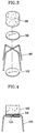
- FIGS. 3 and 4 show an exploded perspective view and a assembled sectional view, respectively, of a preferred embodiment of a directly heated cathode structure according to the present invention.
- the directly heated cathode structure comprises a porous pellet 500 of which cavity is impregnated with electron radiating material, a first metal member 510 being fixed to the lower surface of a pellet 500 by brazing, a filament 600 disposed under first metal member 510, and a second metal member 520 welded to first metal member 510 and for supporting filament 600 with filament 600 being in contact with the lower surface of first metal member 510.
- the porous pellet 500 is made of tungsten (W), molybdenum (Mo), ruthenium (Ru), nickel (Ni) and/or tantalum (Ta), and the material used for first and second metal members 510 and 520 includes molybdenum (Mo), tantalum (Ta) and/or tungsten (W).
- a coating layer (not shown) including osmium (Os), ruthenium (Ru) and/or iridium (Ir) is formed.
- the diameter and thickness of pellet 500 are 0.4-2.0mm and 0.2-1.0mm, respectively, and that the diameter and thickness of first and second metal members 510 and 520 are 0.3-3.0mm and 20-200 ⁇ m, respectively. It is also preferred that the diameter of filament 600 interposed between the first and second metal members is 30-200 ⁇ m.
- first metal member 510 and second metal member 520 laser welding, arc welding or plasma welding can be employed.
- filaments are arranged either cross-wise or radially, to achieve more efficient pellet heating.
- powder of tungsten (W), molybdenum (Mo), ruthenium (Ru), nickel (Ni) and/or tantalum (Ta) is shaped by compression into a column and is then sintered.
- a columnar material 50 is severed at a predetermined length to obtain a unit porous pellet 500.
- the cross section of the pellet may be circular or polygonal.
- porous pellet 500 contacted by cathode material 600, is heated at a high temperature so that the cathode material can be impregnated into cavities of the porous pellet.
- a brazing weld layer 700 including ruthenium (Ru) and/or Molybdenum (Mo) is formed on the lower surface of the pellet to a thickness of 10-100 ⁇ m.
- first plate metal member 510 including molybdenum (Mo), tungsten (W) and/or tantalum (Ta) is contacted with brazing weld layer 700, and then first plate metal member 510 and brazing weld layer 700 are heated to a high temperature, so that first metal member 510 is attached to the lower surface of the pellet by the melted brazing weld layer 700.
- Mo molybdenum
- W tungsten
- Ta tantalum
- a single filament or crossed filament 600 is arranged on first metal member 510, and a second plate metal member 520 is put thereon. Then, the second metal member is welded to first metal member so that a cathode structure of the present invention is obtained.
- the step in which the cathode material is impregnated into the pellet is performed after the first metal member is coupled to the pellet by the brazing weld, in contrast to the above-mentioned embodiment. Accordingly, the order of impregnation of the cathode material can be changed, if required, in a manufacturing method of the directly heated cathode according to the present invention.
- the cathode structure manufactured by the above method of the present invention has merits as discussed below.
- the filament is fixed to the lower surface of pellet 500 between the first and second plate members.
- the structure of the filament fixed to the pellet is stabilized so as to have a large strength against external impact.
- cathode structures manufactured in accordance with manufacturing methods for directly heated cathode structure according to the present invention can contribute to the improvement of product quality and productivity due to the strong pellet structure and improved weld process.
- Cathode structures according to the present invention can also be used in color CRTs for large-screen televisions and computer monitors, as well as in small black-and-white CRTs.
Landscapes
- Solid Thermionic Cathode (AREA)
- Electrodes For Cathode-Ray Tubes (AREA)
Applications Claiming Priority (2)
| Application Number | Priority Date | Filing Date | Title |
|---|---|---|---|
| KR19940038999 | 1994-12-29 | ||
| KR9438999 | 1994-12-29 |
Publications (2)
| Publication Number | Publication Date |
|---|---|
| EP0720198A1 true EP0720198A1 (fr) | 1996-07-03 |
| EP0720198B1 EP0720198B1 (fr) | 1999-06-09 |
Family
ID=19405205
Family Applications (1)
| Application Number | Title | Priority Date | Filing Date |
|---|---|---|---|
| EP95309471A Expired - Lifetime EP0720198B1 (fr) | 1994-12-29 | 1995-12-27 | Structure de cathode chauffée directement et son procédé de fabrication |
Country Status (11)
| Country | Link |
|---|---|
| US (1) | US5701052A (fr) |
| EP (1) | EP0720198B1 (fr) |
| JP (1) | JPH08236009A (fr) |
| KR (1) | KR100195167B1 (fr) |
| CN (1) | CN1084924C (fr) |
| CZ (1) | CZ290440B6 (fr) |
| DE (1) | DE69510169T2 (fr) |
| ES (1) | ES2129304B1 (fr) |
| HU (1) | HU217164B (fr) |
| RU (1) | RU2155409C2 (fr) |
| TW (1) | TW413392U (fr) |
Families Citing this family (4)
| Publication number | Priority date | Publication date | Assignee | Title |
|---|---|---|---|---|
| UA28130C2 (uk) * | 1998-11-09 | 2000-10-16 | Товариство З Обмеженою Відповідальністю "Нікос-Еко" | Катодний вузол прямого розжарення для електронно-променевих приладів |
| US20030025435A1 (en) * | 1999-11-24 | 2003-02-06 | Vancil Bernard K. | Reservoir dispenser cathode and method of manufacture |
| US7791047B2 (en) * | 2003-12-12 | 2010-09-07 | Semequip, Inc. | Method and apparatus for extracting ions from an ion source for use in ion implantation |
| CN111243917B (zh) * | 2020-01-19 | 2021-12-07 | 中国科学院电子学研究所 | 一种阴极热子组件及其制备方法 |
Citations (11)
| Publication number | Priority date | Publication date | Assignee | Title |
|---|---|---|---|---|
| US3495122A (en) * | 1967-07-17 | 1970-02-10 | Siemens Ag | Indirectly heated supply cathode |
| US3671792A (en) * | 1969-10-29 | 1972-06-20 | Itt | Fast warm-up indirectly heated cathode structure |
| GB2060246A (en) * | 1979-10-01 | 1981-04-29 | Hitachi Ltd | Impregnated cathode |
| US4350920A (en) * | 1979-07-17 | 1982-09-21 | U.S. Philips Corporation | Dispenser cathode |
| JPS6059641A (ja) * | 1983-09-09 | 1985-04-06 | Nec Corp | 電子ビ−ムを発生する装置 |
| EP0157634A2 (fr) * | 1984-04-02 | 1985-10-09 | Varian Associates, Inc. | Cathode à réserve contenant du tungstène et de l'iridium |
| JPS6151723A (ja) * | 1985-06-28 | 1986-03-14 | Hitachi Ltd | 直熱含浸形陰極構体 |
| JPS61163532A (ja) * | 1985-01-11 | 1986-07-24 | Toshiba Corp | 含浸型陰極構体 |
| JPS61216222A (ja) * | 1985-03-22 | 1986-09-25 | Toshiba Corp | 含浸型陰極構体 |
| DE8705725U1 (de) * | 1986-09-29 | 1987-11-05 | Balzers Hochvakuum Gmbh, 6200 Wiesbaden | Einkristall mit Widerstandsheizung |
| US12050293B2 (en) | 2018-12-19 | 2024-07-30 | Pgs Geophysical As | Medetomidine compositions having improved anti-fouling characteristics |
Family Cites Families (14)
| Publication number | Priority date | Publication date | Assignee | Title |
|---|---|---|---|---|
| JPS536560A (en) * | 1976-07-07 | 1978-01-21 | Hitachi Ltd | Manufacture of cathode for direct heating type cathode ray tube |
| US4137476A (en) * | 1977-05-18 | 1979-01-30 | Denki Kagaku Kogyo Kabushiki Kaisha | Thermionic cathode |
| JPS5559629A (en) * | 1978-10-26 | 1980-05-06 | Toshiba Corp | Directly heated cathode |
| JPS5566819A (en) * | 1978-11-15 | 1980-05-20 | Hitachi Ltd | Oxide cathode for electron tube |
| US4248114A (en) * | 1979-02-28 | 1981-02-03 | Fiber Industries, Inc. | Cutter of elongated material |
| JPS55144631A (en) * | 1979-04-28 | 1980-11-11 | Hitachi Ltd | Directly-heated cathode for electronic tube |
| JPS563935A (en) * | 1979-06-21 | 1981-01-16 | Toshiba Corp | Direct heating type cathode structure |
| US4369392A (en) * | 1979-09-20 | 1983-01-18 | Matsushita Electric Industrial Co., Ltd. | Oxide-coated cathode and method of producing the same |
| JPS6121622A (ja) * | 1985-06-24 | 1986-01-30 | Hitachi Ltd | Pcm符号器 |
| US4823044A (en) * | 1988-02-10 | 1989-04-18 | Ceradyne, Inc. | Dispenser cathode and method of manufacture therefor |
| US5057736A (en) * | 1989-04-07 | 1991-10-15 | Nec Corporation | Directly-heated cathode structure |
| KR920001335B1 (ko) * | 1989-11-10 | 1992-02-10 | 삼성전관 주식회사 | 디스펜서 음극 |
| KR930014673A (ko) * | 1991-12-20 | 1993-07-23 | 김정배 | 함침형 음극 구조체 및 그 제조방법 |
| JPH08222119A (ja) * | 1994-12-07 | 1996-08-30 | Samsung Display Devices Co Ltd | 直熱形陰極構造体 |
-
1995
- 1995-09-19 KR KR1019950030694A patent/KR100195167B1/ko not_active Expired - Fee Related
- 1995-12-26 TW TW087207742U patent/TW413392U/zh not_active IP Right Cessation
- 1995-12-26 JP JP33889895A patent/JPH08236009A/ja active Pending
- 1995-12-27 EP EP95309471A patent/EP0720198B1/fr not_active Expired - Lifetime
- 1995-12-27 DE DE69510169T patent/DE69510169T2/de not_active Expired - Fee Related
- 1995-12-27 US US08/579,519 patent/US5701052A/en not_active Expired - Fee Related
- 1995-12-28 RU RU95122413/09A patent/RU2155409C2/ru active
- 1995-12-28 HU HU9503849A patent/HU217164B/hu not_active IP Right Cessation
- 1995-12-28 CN CN95121819A patent/CN1084924C/zh not_active Expired - Fee Related
- 1995-12-28 ES ES009502535A patent/ES2129304B1/es not_active Expired - Lifetime
- 1995-12-28 CZ CZ19953490A patent/CZ290440B6/cs not_active IP Right Cessation
Patent Citations (11)
| Publication number | Priority date | Publication date | Assignee | Title |
|---|---|---|---|---|
| US3495122A (en) * | 1967-07-17 | 1970-02-10 | Siemens Ag | Indirectly heated supply cathode |
| US3671792A (en) * | 1969-10-29 | 1972-06-20 | Itt | Fast warm-up indirectly heated cathode structure |
| US4350920A (en) * | 1979-07-17 | 1982-09-21 | U.S. Philips Corporation | Dispenser cathode |
| GB2060246A (en) * | 1979-10-01 | 1981-04-29 | Hitachi Ltd | Impregnated cathode |
| JPS6059641A (ja) * | 1983-09-09 | 1985-04-06 | Nec Corp | 電子ビ−ムを発生する装置 |
| EP0157634A2 (fr) * | 1984-04-02 | 1985-10-09 | Varian Associates, Inc. | Cathode à réserve contenant du tungstène et de l'iridium |
| JPS61163532A (ja) * | 1985-01-11 | 1986-07-24 | Toshiba Corp | 含浸型陰極構体 |
| JPS61216222A (ja) * | 1985-03-22 | 1986-09-25 | Toshiba Corp | 含浸型陰極構体 |
| JPS6151723A (ja) * | 1985-06-28 | 1986-03-14 | Hitachi Ltd | 直熱含浸形陰極構体 |
| DE8705725U1 (de) * | 1986-09-29 | 1987-11-05 | Balzers Hochvakuum Gmbh, 6200 Wiesbaden | Einkristall mit Widerstandsheizung |
| US12050293B2 (en) | 2018-12-19 | 2024-07-30 | Pgs Geophysical As | Medetomidine compositions having improved anti-fouling characteristics |
Non-Patent Citations (4)
| Title |
|---|
| PATENT ABSTRACTS OF JAPAN vol. 009, no. 193 (E - 334) 9 August 1985 (1985-08-09) * |
| PATENT ABSTRACTS OF JAPAN vol. 010, no. 213 (E - 422) 25 July 1986 (1986-07-25) * |
| PATENT ABSTRACTS OF JAPAN vol. 010, no. 367 (E - 462) 9 December 1986 (1986-12-09) * |
| PATENT ABSTRACTS OF JAPAN vol. 011, no. 055 (E - 481) 20 February 1987 (1987-02-20) * |
Also Published As
| Publication number | Publication date |
|---|---|
| ES2129304B1 (es) | 2000-01-01 |
| CN1084924C (zh) | 2002-05-15 |
| US5701052A (en) | 1997-12-23 |
| KR960025904A (ko) | 1996-07-20 |
| HUT74345A (en) | 1996-12-30 |
| HU9503849D0 (en) | 1996-02-28 |
| ES2129304A1 (es) | 1999-06-01 |
| TW413392U (en) | 2000-11-21 |
| EP0720198B1 (fr) | 1999-06-09 |
| JPH08236009A (ja) | 1996-09-13 |
| RU2155409C2 (ru) | 2000-08-27 |
| CZ290440B6 (cs) | 2002-07-17 |
| CN1133483A (zh) | 1996-10-16 |
| DE69510169T2 (de) | 1999-12-16 |
| DE69510169D1 (de) | 1999-07-15 |
| KR100195167B1 (ko) | 1999-06-15 |
| CZ349095A3 (en) | 1996-07-17 |
| HU217164B (hu) | 1999-11-29 |
Similar Documents
| Publication | Publication Date | Title |
|---|---|---|
| US6304024B1 (en) | Impregnated-type cathode substrate with large particle diameter low porosity region and small particle diameter high porosity region | |
| EP0720198B1 (fr) | Structure de cathode chauffée directement et son procédé de fabrication | |
| US5703429A (en) | Directly heated cathode structure | |
| JPH0785775A (ja) | 直熱形ディスペンサ陰極構造体 | |
| US20030117054A1 (en) | Cathode structure, and production method therefor and electron gun and cathode ray tube | |
| US5668434A (en) | Directly heated cathode for cathode ray tube | |
| US3467879A (en) | Planar dispenser cathode assembly with a cap member to which an electronemissive,tubular heater,and rodshaped support members are clamped | |
| US5852342A (en) | Directly heated cathode structure | |
| KR100319089B1 (ko) | 직열형음극구조체및그제조방법 | |
| WO1996039709A1 (fr) | Cathode a diffusion a chauffage direct, et procede de fabrication | |
| JP3720913B2 (ja) | 含浸型陰極構体、これに用いられる陰極基体及びこれを用いた電子管 | |
| US5459372A (en) | Impregnated cathode structure | |
| KR0147615B1 (ko) | 직열형 음극구조체 | |
| KR0147609B1 (ko) | 직열형 음극구조체 | |
| US5451831A (en) | Impregnated pellet for a cathode structure and method of producing the same | |
| KR100342042B1 (ko) | 직열형 음극구조체 | |
| US6252342B1 (en) | Impregnated cathode structure for a CRT and its manufacturing method | |
| JP2004503905A (ja) | 改善された酸化物被覆陰極及びその製造方法 | |
| GB1583585A (en) | Dispenser cathode | |
| JP2860667B2 (ja) | マグネトロン用陰極 | |
| KR920006821Y1 (ko) | 함침형 음극구조체 | |
| KR20010104552A (ko) | 음극선관용 함침형 음극의 구조 및 그 제조방법 | |
| JPH08102245A (ja) | 直熱型陰極構造体 | |
| JP2003197086A (ja) | 含浸型カソードとその製造方法、並びにそれを用いた電子銃および陰極線管 | |
| JPH08185792A (ja) | 酸化物陰極構体 |
Legal Events
| Date | Code | Title | Description |
|---|---|---|---|
| PUAI | Public reference made under article 153(3) epc to a published international application that has entered the european phase |
Free format text: ORIGINAL CODE: 0009012 |
|
| AK | Designated contracting states |
Kind code of ref document: A1 Designated state(s): DE FR GB |
|
| 17P | Request for examination filed |
Effective date: 19970103 |
|
| GRAG | Despatch of communication of intention to grant |
Free format text: ORIGINAL CODE: EPIDOS AGRA |
|
| 17Q | First examination report despatched |
Effective date: 19980821 |
|
| GRAG | Despatch of communication of intention to grant |
Free format text: ORIGINAL CODE: EPIDOS AGRA |
|
| GRAH | Despatch of communication of intention to grant a patent |
Free format text: ORIGINAL CODE: EPIDOS IGRA |
|
| GRAH | Despatch of communication of intention to grant a patent |
Free format text: ORIGINAL CODE: EPIDOS IGRA |
|
| GRAA | (expected) grant |
Free format text: ORIGINAL CODE: 0009210 |
|
| AK | Designated contracting states |
Kind code of ref document: B1 Designated state(s): DE FR GB |
|
| REF | Corresponds to: |
Ref document number: 69510169 Country of ref document: DE Date of ref document: 19990715 |
|
| ET | Fr: translation filed | ||
| PLBE | No opposition filed within time limit |
Free format text: ORIGINAL CODE: 0009261 |
|
| STAA | Information on the status of an ep patent application or granted ep patent |
Free format text: STATUS: NO OPPOSITION FILED WITHIN TIME LIMIT |
|
| 26N | No opposition filed | ||
| PGFP | Annual fee paid to national office [announced via postgrant information from national office to epo] |
Ref country code: FR Payment date: 20011212 Year of fee payment: 7 |
|
| PGFP | Annual fee paid to national office [announced via postgrant information from national office to epo] |
Ref country code: GB Payment date: 20011227 Year of fee payment: 7 |
|
| REG | Reference to a national code |
Ref country code: GB Ref legal event code: IF02 |
|
| PGFP | Annual fee paid to national office [announced via postgrant information from national office to epo] |
Ref country code: DE Payment date: 20020109 Year of fee payment: 7 |
|
| PG25 | Lapsed in a contracting state [announced via postgrant information from national office to epo] |
Ref country code: GB Free format text: LAPSE BECAUSE OF NON-PAYMENT OF DUE FEES Effective date: 20021227 |
|
| PG25 | Lapsed in a contracting state [announced via postgrant information from national office to epo] |
Ref country code: DE Free format text: LAPSE BECAUSE OF NON-PAYMENT OF DUE FEES Effective date: 20030701 |
|
| GBPC | Gb: european patent ceased through non-payment of renewal fee |
Effective date: 20021227 |
|
| PG25 | Lapsed in a contracting state [announced via postgrant information from national office to epo] |
Ref country code: FR Free format text: LAPSE BECAUSE OF NON-PAYMENT OF DUE FEES Effective date: 20030901 |
|
| REG | Reference to a national code |
Ref country code: FR Ref legal event code: ST |