EP0721554B1 - Einbauelement für unterwasserscheinwerfer - Google Patents
Einbauelement für unterwasserscheinwerfer Download PDFInfo
- Publication number
- EP0721554B1 EP0721554B1 EP95926975A EP95926975A EP0721554B1 EP 0721554 B1 EP0721554 B1 EP 0721554B1 EP 95926975 A EP95926975 A EP 95926975A EP 95926975 A EP95926975 A EP 95926975A EP 0721554 B1 EP0721554 B1 EP 0721554B1
- Authority
- EP
- European Patent Office
- Prior art keywords
- installation element
- flange
- base
- cable
- sealing
- Prior art date
- Legal status (The legal status is an assumption and is not a legal conclusion. Google has not performed a legal analysis and makes no representation as to the accuracy of the status listed.)
- Expired - Lifetime
Links
Images


Classifications
-
- F—MECHANICAL ENGINEERING; LIGHTING; HEATING; WEAPONS; BLASTING
- F21—LIGHTING
- F21S—NON-PORTABLE LIGHTING DEVICES; SYSTEMS THEREOF; VEHICLE LIGHTING DEVICES SPECIALLY ADAPTED FOR VEHICLE EXTERIORS
- F21S8/00—Lighting devices intended for fixed installation
-
- F—MECHANICAL ENGINEERING; LIGHTING; HEATING; WEAPONS; BLASTING
- F21—LIGHTING
- F21W—INDEXING SCHEME ASSOCIATED WITH SUBCLASSES F21K, F21L, F21S and F21V, RELATING TO USES OR APPLICATIONS OF LIGHTING DEVICES OR SYSTEMS
- F21W2131/00—Use or application of lighting devices or systems not provided for in codes F21W2102/00-F21W2121/00
- F21W2131/40—Lighting for industrial, commercial, recreational or military use
- F21W2131/401—Lighting for industrial, commercial, recreational or military use for swimming pools
Definitions
- the invention relates to a built-in element for receiving and attachment of an underwater spotlight for water-filled Basin as it is closer in the preamble of claim 1 is designated.
- the underwater spotlight be used in mineral water or brine baths.
- the cable for the power supply of the underwater spotlight is for usually through a precautionary measure into the wall or floor empty pipe encased in concrete up to the installation element guided. There it passes through a sealing cable gland through into the built-in element and is finally at the Underwater lights connected.
- This cable gland is of course also subject to the corrosive effect of Water or the brine inside the flooded installation element.
- the actual sealing Used rubber sealing rings lose through over time Aging and embrittlement processes their sealing effect. If accelerate the built-in element with a brine these processes are of course quite significant.
- the Invention the task, the life of a built-in element to extend for underwater spotlights that the Sealing - especially in the case of cable entry - that Cooling and corrosion resistance improved, and that Maintenance is simplified.
- the inventive Installation element allow the underwater spotlight does not affect the water quality of the pool and always visually appealing and symmetrical inserts into the tile grid of the basin.
- the object is achieved in particular thereby achieved that pure water flows through the installation element can be.
- This does not lead to how general usual, only a conduit that runs through the wall or the bottom of the basin to the built-in element, but is a both cable and pure water supply pipe integrally connected to the installation element according to the invention. On this integral connection point does not encounter any sealing problems as with the usual routing of the cable through a concrete, directly to the installation element subsequent sealing cable gland.
- - pure water supply and cable routing - is the cooling of the power cable ensured over the entire length of the pipe.
- Supply pipe e.g. on, in or on top of Pipe end to cut a sealing pipe thread over the one Threaded plugs can also be installed can.
- the plug can also be in or on the Feed pipe pushed and glued to it.
- This Sealing plugs must of course have an axial bore for the passage of the cable. This hole widens Formation of a paragraph in the direction of the cable outlet in the drying or maintenance room to a coaxial bore larger diameter on which a sealing cable gland records.
- a sealing element e.g. on Rubber sealing ring, from a pressure screw with external thread and Axial bore, the inside diameter of which is approximately the cable diameter corresponds to the paragraph at the foot of the hole larger diameter tightly pressed.
- the external thread of the Pressure screw works with a larger diameter in the bore provided internal thread together.
- Downstream of the Sealing plug is a pipe with pure water discharge Pure water connection by welding pipes to the supply pipe welded.
- the cable and water connection can be installed more easily End of the supply pipe through the use of a T-piece to reach.
- the supply pipe Even screwed over a pipe thread or also glued integrally, with the second arm of the T-piece sealing plug with cable entry described above Screwed or glued and sealed in the third arm of the T-piece finally opens the pipe over which Pure water is fed into the supply pipe. This The transition is of course also through a pipe fitting or sealed by gluing.
- the invention Installation element initially more or less exact positioned in the wall or floor of the pool.
- the position of the underwater spotlight in the installation element again, however, it is not like conventional models the state of the art (by prefabricated Threaded holes for attaching the underwater spotlight in the built-in element) from the outset.
- the built-in element Underwater spotlights taking advantage of a certain Mounting tolerance in the mounting element to fix and so possible inaccurate positioning of the built-in element in the Compensate the concrete wall or floor.
- the underwater spotlight always optimally symmetrical in that Tile grid of the basin can be fitted, so that both a optically appealing appearance arises as well Adjustment and cutting work on the tiles minimized can be.
- This is according to the invention by a on the inner bottom of the mounting element attachable base reached on which the underwater spotlight either is mounted directly or via a known rotary bracket.
- this base must be placed on the basin wall or floor first of all in a plane parallel to this plane be displaceable at the bottom of the built-in element. He points to that a groove in the one in the center of the base of the built-in element firmly anchored bolt protrudes. The base is therefore along this bolt by guiding the groove on the bottom of the installation element slidable.
- this groove is particularly advantageous to use this groove to be designed in a T-shape and a threaded bolt use because this way in addition to the movability at the same time the fixability of the base in a certain Position can be ensured.
- the base can be screwed on a nut on the threaded bolt and its subsequent Tightened against the heel of the T-shaped groove become.
- a screw that e.g. in one in the center of the bottom plate trained threaded hole sits.
- the base however, be formed in two parts.
- the first component of the base is fully assembled Condition partly due to the second component of the base covered so that free access to it is only possible if the second component of the base is removable.
- this first component of the base once in its as optimal determined position fixed on the floor of the installation element, can the second component by means of already prefabricated Tapped holes in the first and second component Fastening centered on the first component become.
- On this second component of the base can now again a U-profile-like swivel bracket or an immediate one to the underwater spotlight holding pot via a prefabricated, centered on the second installation element Tapped hole can be fastened by a screw connection.
- An installation tolerance perpendicular to the wall or floor level of the Basin can be different by interposing slices Thickness can be exhausted. In the swivel bracket or Recording pot eventually becomes conventional and well known Way of underwater lights mounted.
- the housing body of the installation element must also be achieved a vertical installation tolerance can be adjusted in height. He essentially exposes itself from the base plate a jacketed, cylindrical or prismatic pipe section, an annular base flange, an annular Press flange and another pipe section together. While The dimensions of the first three components are specified Length of the final pipe section, on its free Finally, the front of the underwater spotlight with a radially molded flange always comes into contact Achievement of the maximum installation tolerance dimensioned so by shortening the pipe section the required length can be obtained.
- the cable and pure water supply pipe in the housing body In the area of this covered pipe section, the cable and pure water supply pipe in the housing body.
- the supply pipe with the wall of the housing body is also included sealed by gluing or welding. It passes through an inlet bore in the jacketed pipe section and a coaxial and congruent inlet bore in the pipe sleeve in such a way that the supply pipe with the covered pipe section and the pipe sleeve together forms a firm sandwich.
- the to be placed between the base flange and the press flange and with a circular section with approximately the same radius as the sealing film of the basin to be provided for the installation element is already in the screwing of the base flange and press flange pressing and sealing between these two flanges forced. It is particularly advantageous to use the circular To make the cutout of the sealing film a little larger, see above that they nowhere to the radially inner edge of the annular base flange and the annular press flange enough.
- the resulting disk-shaped space between the press and base flange can then completely with be filled with an adhesive that can be used except for the Inner surfaces of the two flanges extends. So are Base flange, press flange, and sealing film integral with each other connected.
- This sealing connection can be even more secure be designed if in the housing body at the level of Basic and press flange a pipe socket is fitted, because this through the on the inner surfaces of the two Adhesive escaping flanges, at least with base and press flange forms an integral sandwich composite.
- the pipe socket can also be an integral in this way Sandwich composite between the covered pipe section, base flange, Press flange, final pipe section and fitted Pipe socket can be reached.
- the fitted pipe socket is even on two Places associated with adhesive.
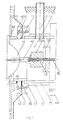
- Fig. 1 shows a complete, already fully assembled installation element 1, in which the underwater spotlight 6 on a U-profile Swivel bracket 8 is mounted. That through that Feed pipe 4 guided, depending on the required length several times wrapped around the base 21 inside the built-in element and finally connected to the underwater spotlight 6 Cable is not shown for reasons of clarity. For the same reasons it is only in the left half of the drawing, the adhesive 20 is shown blackened, and the one that can optionally be fitted into the housing body 3 Pipe socket 18 shown.
- the housing body 3 settles from the components pipe section 13, base flange 15, press flange 16 and pipe section 17 together, forming an integral Sandwich composite are glued together.
- the housing body 3 over its from a pipe sleeve 14 encased pipe section 13 in a circular groove in the base plate 2 anchored and integrally glued to the base plate 2 connected.
- Pipe section 13 and pipe sleeve 14 are from broken through a coaxial and congruent inlet bore, via which the feed pipe 4 into the interior of the installation element 1 flows.
- the opposite end of the feed pipe 4 opens into one Drying or maintenance room, which is shown schematically in FIG final hatching around the supply pipe 4 is to be indicated.
- Supply pipe 4, pipe section 13 and pipe sleeve 14 also form an integral sandwich composite by gluing.
- Base flange 15 and press flange 16 are initially only connected via a detachable screw connection 19, so that when installing the built-in element 1 between Pool wall or floor 9 and tile structure 10 arranged Sealing film 11 between the axially outer end face of the base flange 15 and axially inner end face of the press flange 16 can be inserted.
- Screw connection 19 between base flange 15 and Press flange 16 thus hermetically seals the sealing film pressed.
- the circular cutout in the sealing film 11 a larger diameter than the inner diameter of the housing body 3 have, so that the sealing film 11 at none Place up to the inner surface of the base or press flange 15, 16 is sufficient and rather an annular disc Joint remains between base flange 15 and press flange 16.
- This can be filled with an adhesive 20 which is up to penetrates the inside of the two flanges and this so together with the sealing film 11 to form an integral sandwich composite connects.
- annular sealing film cutout 12 is provided to seal the heads of the screws 19, which in the axially outer end face of the press flange 16 sunk are and serve to connect to the base flange 15 .
- the underwater spotlight 6 itself is thereby in the installation element 1 attached that he on the one hand on the axially outer End face of the final pipe section 17 glued to another by a screw connection shown in dashed lines is attached to the rotary bracket 8.
- the rotary bracket 8 is again via a screw connection in the middle of the component 23 of the base 21 attached.
- the component is in the same way 23 centered on the component 22 of the base a screw connection shown in dashed lines.
- the Component 22 and, of course, component 23, the Swivel bracket 8 and the underwater spotlight 6 can be under guidance a T-shaped, radially formed in the component 22 Groove 29 around a from the center of the base plate 2 in the Installation element 1 projecting screw 24 rotated and into an eccentric Position to be moved. In this desired The entire ensemble can be positioned from the the center of the base plate 2 through the T-shaped groove 29 protruding screw 24 are fixed.
- Fig. 1 the installation element 1 according to the invention is finished shown installed state.
- All are Base flange 15 projecting components, so press flange 16, Underwater spotlight 6, possibly also the pipe socket 17.18, not yet assembled.
- a mounting plate made of recycling material centered on the base flange 15 screwed. It serves as a mold core and when concreting so to speak "placeholder" for the components to be assembled later (see above). Therefore, from the base flange 15 towards the bevelled course of the concrete wall 9 still the outline to recognize the mounting plate originally used.
- the mounting plate preferably has a ventilation hole on when pressing the built-in element and thus connected pure water pipe system for leak testing is helpful.
- the ventilation hole remains for the purpose of Venting initially open. For subsequent impressions then sealed them with a stopper.
- the mounting plate After pressing the mounting plate can be removed and the entire "structure" (see above) above the base flange 15 mounted or glued to the sealing sheets 11, 12 of the pool become.
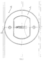
- the built-in element 1 or the built-in Frontal condition shows only visible underwater lights 6. This occurs through the narrow outlet openings 25 the supply pipe 4 into the installation element 1 flowing pure water into the basin. About the two screws whose Hexagon heads are visible, is the underwater spotlight 6 attached to the rotary bracket 8. An optimally symmetrical The headlight fits into the tile grid the setting options of the base 21 reached.
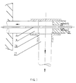
- Fig. 3 shows that End of the feed pipe 4 in longitudinal section, that opens into the drying or maintenance room, which in turn through a final hatching surrounding the supply pipe is indicated schematically.
- the end of Supply pipe 4 is in one arm of a T-shaped pipe fitting 28 glued and connected to this sealing.
- a sealing cable gland 26 receiving sealing plug glued.
- Tubular arm of the T-shaped connector 28 is finally glued the end of a tube 27 over the pure water is fed into the feed pipe 4.
- the direction of flow of the pure water is symbolized by arrows.
- All three tubular arms taper their entrance diameter forming a paragraph that acts as a stop for each pipe ends to be inserted and glued or for the Sealing plug is used.
- the cable 5 passes through the supply pipe 4 coming here first one axially in the plug trained bore. This hole widens with formation a paragraph in the direction of the drying or maintenance room to a larger diameter hole that the sealing Cable gland 26 takes.
- This has a pressure screw with a central bore whose diameter is approximately the same Corresponds to the cable diameter, and through which the cable in the Drying room is led.
- the pressure screw is from the drying room from a larger diameter of the Sealing plug cut internal thread against the as Stop serving paragraph at the transition of the two bore diameters screwed into the plug. In doing so, a rubber sealing ring inserted between heel and pressure screw sealed around the cable.
- Both components 22 and 23 are cylindrical in shape.
- in the Component 22 is a T-shaped radially starting from the center Groove 29 formed. For technical reasons this groove is also a flat groove with a rectangular cross-section beyond the axis of component 22 as a continuation of the T-shaped Radially formed groove.
- Fig. 5 shows the base 21 again as an axial section and in Top view, with the prefabricated ones being particularly clear Bores for the later screw connections and the T-shape the groove 29 are visible.
- the axial centered bore in the Component 23 takes the screw for mounting during assembly of the rotary bracket 8. It is made of two holes framed, starting from the free end face of the Component 23 inside this component 23 with formation taper a paragraph and with this tapered diameter extend into the component 22. Over these two holes is the component 23 on the component 22 by screwing attachable.
Landscapes
- Engineering & Computer Science (AREA)
- General Engineering & Computer Science (AREA)
- Installation Of Indoor Wiring (AREA)
- Aerials With Secondary Devices (AREA)
- Road Signs Or Road Markings (AREA)
- Arrangement Of Elements, Cooling, Sealing, Or The Like Of Lighting Devices (AREA)
- Non-Portable Lighting Devices Or Systems Thereof (AREA)
- Domestic Plumbing Installations (AREA)
Description
- Fig. 1
- einen Axialschnitt des fertig montierten Einbauelements;
- Fig. 2
- eine Draufsicht auf das fertig montierte Einbauelement, bzw. auf den Unterwasserscheinwerfer;
- Fig. 3
- einen axialen Längsschnitt des in den Trockenraum ragenden Zuleitungsrohrendes;
- Fig. 4
- eine perspektivische Darstellung des Sockels, auf dem der Unterwasserscheinwerfer befestigbar ist; und
- Fig. 5
- einen Axialschnitt und eine Draufsicht dieses Sockels.
Claims (12)
- Im wesentlichen topfartig aus einer Bodenplatte und einem Gehäusekörper zusammengesetztes, in die Wand oder den Boden eines wassergefüllten, insbesondere mit Sole oder Mineralwasser gefüllten, Beckens einbetonierbares, flutbares Einbauelement zur Aufnahme und Befestigung eines Unterwasserscheinwerfers, der das Einbauelement deckelartig und im wesentlichen bündig zur Wand bzw. zum Boden des Beckens abschließt, wobei sich zur Stromversorgung des Unterwasserscheinwerfers ein Kabel bis in das Einbauelement hinein erstreckt, dessen Durchführung gegen Wasseraustritt aus dem gefluteten Einbauelement abgedichtet ist,
gekennzeichnet durch
ein an seinem einen Ende integral mit dem Einbauelement (1) verbundenes und mit seinem anderen, freien Ende in einen Trockenraum ragendes Zuleitungsrohr (4), durch das sowohl das Kabel (5) geführt ist, als auch Reinwasser zum Durchströmen des Einbauelements (1) einleitbar ist, wobei das Kabel (5) durch eine im Trockenraum frei zugängliche, dichtende Kabelverschraubung (26) in das Zuleitungsrohr (4) eingeführt ist. - Einbauelement nach Anspruch 1,
dadurch gekennzeichnet,
daß das Kabel (5) im Inneren des Einbauelements (1) in solcher Länge vorrätig ist, daß der Unterwasserscheinwerfer (6) ohne Manipulation an der dichtenden Kabelverschraubung (26) aus dem im Becken installierten Einbauelement (1) herausmontiert und mit angeschlossenem Kabel (5) auch über größere Entfernungen auf dem Beckenrand abgelegt werden kann. - Einbauelement nach einem der Ansprüche 1 oder 2,
gekennzeichnet durch
einen zweiteiligen Sockel (21) im Inneren des Gehäusekörpers (3), dessen erstes Bauelement (22) unter Führung einer im ersten Bauelement (22) ausgebildeten Nut (29), in die ein im Zentrum der Bodenplatte (2) des Einbauelements (1) befestigter Bolzen greift, verschiebbar und um den Bolzen drehbar ist, während dessen zweites Bauelement (23) auf dem ersten Bauelement (22) zentriert befestigbar ist und entweder über einen Drehbügel (8) oder unmittelbar mit dem Unterwasserscheinwerfer (6) verbunden ist. - Einbauelement nach einem der Ansprüche 1 bis 3,
dadurch gekennzeichnet,
daß sich der Gehäusekörper (3) von der Bodenplatte (2) ausgehend im wesentlichen aus einem ummantelten, zylindrischen oder prismatischen Rohrabschnitt (13), einem ringförmigen Grundflansch (15), einem ringförmigen Preßflansch (16) und einem weiteren Rohrabschnitt (17) zusammensetzt, auf dessen freier Stirnseite schließlich der Unterwaserscheinwerfer (6) mit einem radial außen angeformten Flansch (7) zur Auflage kommt. - Einbauelement nach Anspruch 4,
dadurch gekennzeichnet,
daß der ummantelte Rohrabschnitt (13) des Gehäusekörpers (3) mit seinen stirnseitigen Randbereichen in komplementäre Ringnutprofile in der axial inneren Oberfläche der Bodenplatte (2) mit Paßsitz eingepaßt und hermetisch dichtend eingeklebt ist. - Einbauelement nach einem der Ansprüche 4 oder 5,
dadurch gekennzeichnet,
daß der ummantelte Rohrabschnitt (13) des Gehäusekörpers (3) flächenbündig und insbesondere durch Verkleben zu einem Sandwichverbund von einer Rohrmanschette (14) umschlossen ist, deren eine Stirnseite flächenbündig auf der axial inneren Oberfläche des Grundflansches (15) aufliegt und mit dieser insbesondere durch Verkleben sandwichartig verbunden ist, während die andere Stirnseite der Rohrmanschette (14) in gleicher Weise mit der axial inneren Oberfläche der Bodenplatte (2) flächenbündig in Berührung steht und mit dieser zusätzlich insbesondere unter Bildung eines ebenfalls sandwichartigen Verbundes integral verbunden ist. - Einbauelement nach einem der Ansprüche 1 bis 6
dadurch gekennzeichnet,
daß das Zuleitungsrohr (4), das mit der Wand des Gehäusekörpers (3) durch Verkleben oder Verschweißen dichtend verbunden ist, eine Einlaßbohrung in dem ummantelten Rohrabschnitt (13) des Gehäusekörpers (3) und eine koaxiale und kongruente Einlaßbohrung in der Rohrmanschette (14) so durchsetzt, daß das Zuleitungsrohr (4) mit dem ummantelten Rohrabschnitt (13) des Gehäusekörpers (3) und der Rohrmanschette (14) gemeinsam einen festen Sandwichverbund bildet. - Einbauelement nach einem der Ansprüche 4 bis 7,
dadurch gekennzeichnet,
daß der Preßflansch (16) auf dem Grundflansch (15) über Schraubverbindungen (19) befestigbar ist und dabei eine zwischen Betonwand (9) bzw. -boden und Fliesenaufbau (10) des Beckens geführte Dichtfolie (11) verpressend und dichtend zwischen Grundflansch (15) und Preßflansch (16) gezwungen werden kann. - Einbauelement nach Anspruch 8,
dadurch gekennzeichnet,
daß die Dichtfolie (11) an keiner Stelle bis an den radial inneren Rand des ringförmigen Grundflansches (15) und des ringförmigen Preßflansches (16) reicht, und daß der dadurch entstehende ringscheibenförmige Raum vollständig mit einem Klebmittel (20) ausgefüllt ist, das sich bis auf die Mantelinnenflächen der beiden Flansche (15, 16) erstreckt, so daß Grundflansch (15) und Preßflansch (16) an ihrem radial inneren Bereich integral verbunden sind. - Einbauelement nach Anspruch 9,
dadurch gekennzeichnet,
daß in den Gehäusekörper (3) ein Rohrstutzen (18) eingepaßt ist, der sich mindestens über die Mantelinnenflächen von Grund- (15) und Preßflansch (16) erstreckt, und mindestens mit diesen durch das Klebmittel (20) zu einem integralen Sandwichverbund verbunden ist. - Einbauelement nach einem der Ansprüche 8 bis 10 ,
dadurch gekennzeichnet,
daß ein zusätzlicher ringförmiger Dichtfolienausschnitt (12) mit seinem radial äußeren Bereich auf der eigentlichen Dichtfolie (11) des Beckens und mit seinem radial inneren Bereich auf der axial äußeren Seite des Preßflansches (16) zur Auflage kommt, mit diesen dichtend verklebt ist und so die Köpfe der Schrauben (19) dichtend überdeckt, die in die axial äußere Seite des Preßflansches (16) eingesenkt sind, und mit denen der Preßflansch (16) unter Zwischenlage der Dichtfolie (11) auf den Grundflansch (15) aufgeschraubt ist. - Einbauelement nach einem der Ansprüche 1 bis 11,
dadurch gekennzeichnet,
daß es aus Kunststoff, insbesondere aus PVC besteht.
Applications Claiming Priority (5)
| Application Number | Priority Date | Filing Date | Title |
|---|---|---|---|
| DE4426586 | 1994-07-27 | ||
| DE4426586 | 1994-07-27 | ||
| DE4430220A DE4430220C2 (de) | 1994-08-25 | 1994-08-25 | Verfahren zur Steuerung der Laserstrahlintensitätsverteilung auf der Oberfläche zu bearbeitender Bauteile |
| DE4430220 | 1994-08-25 | ||
| PCT/EP1995/002922 WO1996003608A1 (de) | 1994-07-27 | 1995-07-24 | Einbauelement für unterwasserscheinwerfer |
Publications (2)
| Publication Number | Publication Date |
|---|---|
| EP0721554A1 EP0721554A1 (de) | 1996-07-17 |
| EP0721554B1 true EP0721554B1 (de) | 2000-06-07 |
Family
ID=25938731
Family Applications (1)
| Application Number | Title | Priority Date | Filing Date |
|---|---|---|---|
| EP95926975A Expired - Lifetime EP0721554B1 (de) | 1994-07-27 | 1995-07-24 | Einbauelement für unterwasserscheinwerfer |
Country Status (5)
| Country | Link |
|---|---|
| EP (1) | EP0721554B1 (de) |
| AT (1) | ATE193763T1 (de) |
| CZ (1) | CZ289448B6 (de) |
| HU (1) | HU216384B (de) |
| WO (1) | WO1996003608A1 (de) |
Family Cites Families (3)
| Publication number | Priority date | Publication date | Assignee | Title |
|---|---|---|---|---|
| US1792398A (en) * | 1929-07-12 | 1931-02-10 | Russell & Stoll Company | Illuminating unit for swimming pools |
| US3949213A (en) * | 1974-02-11 | 1976-04-06 | Hayward Manufacturing Company, Inc. | Underwater light |
| US5122936A (en) * | 1991-05-13 | 1992-06-16 | Spa Electrics Pty. Ltd. | Swimming pool lighting |
-
1995
- 1995-07-24 WO PCT/EP1995/002922 patent/WO1996003608A1/de not_active Ceased
- 1995-07-24 CZ CZ1996897A patent/CZ289448B6/cs not_active IP Right Cessation
- 1995-07-24 EP EP95926975A patent/EP0721554B1/de not_active Expired - Lifetime
- 1995-07-24 AT AT95926975T patent/ATE193763T1/de not_active IP Right Cessation
- 1995-07-24 HU HU9600743A patent/HU216384B/hu not_active IP Right Cessation
Also Published As
| Publication number | Publication date |
|---|---|
| HU216384B (hu) | 1999-06-28 |
| EP0721554A1 (de) | 1996-07-17 |
| HU9600743D0 (en) | 1996-05-28 |
| CZ89796A3 (en) | 1997-09-17 |
| ATE193763T1 (de) | 2000-06-15 |
| HUT73360A (en) | 1996-07-29 |
| WO1996003608A1 (de) | 1996-02-08 |
| CZ289448B6 (cs) | 2002-01-16 |
Similar Documents
| Publication | Publication Date | Title |
|---|---|---|
| EP0085329B1 (de) | Anschlusseinrichtung für Armaturen | |
| DE102008000049B4 (de) | Hausanschlussvorrichtung und Verfahren zum Herstellen eines Hausanschlusses | |
| DE102017208477A1 (de) | Kabeldurchführung | |
| EP1503026B1 (de) | Punkthalter | |
| DE3308347C2 (de) | Abzweig- und Absperreinrichtung für Kaltwasserversorgungsnetze | |
| DE4430200C2 (de) | Einbauelement zur Aufnahme und Befestigung eines Unterwasserscheinwerfers | |
| EP0131956A1 (de) | Gewinderohrmuffe | |
| EP0042885B1 (de) | Gas-Hausanschlussvorrichtung | |
| EP0721554A1 (de) | Einbauelement für unterwasserscheinwerfer | |
| DE3029533A1 (de) | Gas-hausanschlussvorrichtung | |
| DD263105A1 (de) | Spritzwassergeschuetzte strahlerleuchte | |
| DE3912479C1 (en) | Through passage guide and sealing device - has sealing ring for threaded tube accepting electric cable, gas or water pipe to guide through in building wall | |
| DE102012215704A1 (de) | Leuchtenanordnung, leuchte und verfahren zur herstellung einer leuchtenanordnung | |
| CH455908A (de) | Verbindungs- und Abzweigmuffe für Fernmeldekabel | |
| EP1255072A2 (de) | Wasserdichte rohrförmige Leuchte | |
| DE19547267C2 (de) | Druckwasser- und gasdichte Strahlerleuchte für universelle Anwendung | |
| DE102007007400A1 (de) | Wasserzulaufarmatur | |
| DE9414082U1 (de) | Mauerdurchführung mit Zentrier- und Dichteinsatz | |
| DE4304237A1 (en) | Pipe clip for plastics supply pipes - has plastics cover hood enclosing all function parts set in pipe clip | |
| DE60309311T2 (de) | Rohrabzweigung mit buchse mit einer keilförmigen nut und keil zum einführen in die buchse | |
| DE19654805C1 (de) | Verfahren zum Einsetzen eines Montageteils in eine Wand sowie Montageteil für die Verwendung bei einem solchen Montageverfahren | |
| DE3704321A1 (de) | Fraeser-anbohrarmatur | |
| EP1181484B1 (de) | Einbaugehäuse | |
| CH681237A5 (de) | ||
| EP4675141A1 (de) | Wanddurchführung zur durchführung von leitungen durch eine wand |
Legal Events
| Date | Code | Title | Description |
|---|---|---|---|
| PUAI | Public reference made under article 153(3) epc to a published international application that has entered the european phase |
Free format text: ORIGINAL CODE: 0009012 |
|
| AK | Designated contracting states |
Kind code of ref document: A1 Designated state(s): AT BE CH FR GB IT LI LU NL |
|
| 17P | Request for examination filed |
Effective date: 19960730 |
|
| 17Q | First examination report despatched |
Effective date: 19990127 |
|
| GRAG | Despatch of communication of intention to grant |
Free format text: ORIGINAL CODE: EPIDOS AGRA |
|
| GRAG | Despatch of communication of intention to grant |
Free format text: ORIGINAL CODE: EPIDOS AGRA |
|
| GRAH | Despatch of communication of intention to grant a patent |
Free format text: ORIGINAL CODE: EPIDOS IGRA |
|
| GRAH | Despatch of communication of intention to grant a patent |
Free format text: ORIGINAL CODE: EPIDOS IGRA |
|
| GRAA | (expected) grant |
Free format text: ORIGINAL CODE: 0009210 |
|
| AK | Designated contracting states |
Kind code of ref document: B1 Designated state(s): AT BE CH FR GB IT LI LU NL |
|
| PG25 | Lapsed in a contracting state [announced via postgrant information from national office to epo] |
Ref country code: NL Free format text: LAPSE BECAUSE OF FAILURE TO SUBMIT A TRANSLATION OF THE DESCRIPTION OR TO PAY THE FEE WITHIN THE PRESCRIBED TIME-LIMIT Effective date: 20000607 Ref country code: GB Free format text: LAPSE BECAUSE OF FAILURE TO SUBMIT A TRANSLATION OF THE DESCRIPTION OR TO PAY THE FEE WITHIN THE PRESCRIBED TIME-LIMIT Effective date: 20000607 |
|
| REF | Corresponds to: |
Ref document number: 193763 Country of ref document: AT Date of ref document: 20000615 Kind code of ref document: T |
|
| RIC1 | Information provided on ipc code assigned before grant |
Free format text: 7F 21W 131/401 A |
|
| REG | Reference to a national code |
Ref country code: CH Ref legal event code: NV Representative=s name: SCHMAUDER & PARTNER AG PATENTANWALTSBUERO Ref country code: CH Ref legal event code: EP |
|
| PG25 | Lapsed in a contracting state [announced via postgrant information from national office to epo] |
Ref country code: LU Free format text: LAPSE BECAUSE OF NON-PAYMENT OF DUE FEES Effective date: 20000724 |
|
| PG25 | Lapsed in a contracting state [announced via postgrant information from national office to epo] |
Ref country code: BE Free format text: LAPSE BECAUSE OF NON-PAYMENT OF DUE FEES Effective date: 20000731 |
|
| ET | Fr: translation filed | ||
| ITF | It: translation for a ep patent filed | ||
| NLV1 | Nl: lapsed or annulled due to failure to fulfill the requirements of art. 29p and 29m of the patents act | ||
| GBV | Gb: ep patent (uk) treated as always having been void in accordance with gb section 77(7)/1977 [no translation filed] |
Effective date: 20000607 |
|
| BERE | Be: lapsed |
Owner name: WACH JOHANN FRANZ Effective date: 20000731 |
|
| PLBE | No opposition filed within time limit |
Free format text: ORIGINAL CODE: 0009261 |
|
| STAA | Information on the status of an ep patent application or granted ep patent |
Free format text: STATUS: NO OPPOSITION FILED WITHIN TIME LIMIT |
|
| 26N | No opposition filed | ||
| PGFP | Annual fee paid to national office [announced via postgrant information from national office to epo] |
Ref country code: FR Payment date: 20010719 Year of fee payment: 7 |
|
| PGFP | Annual fee paid to national office [announced via postgrant information from national office to epo] |
Ref country code: AT Payment date: 20010720 Year of fee payment: 7 |
|
| PGFP | Annual fee paid to national office [announced via postgrant information from national office to epo] |
Ref country code: CH Payment date: 20010807 Year of fee payment: 7 |
|
| PG25 | Lapsed in a contracting state [announced via postgrant information from national office to epo] |
Ref country code: AT Free format text: LAPSE BECAUSE OF NON-PAYMENT OF DUE FEES Effective date: 20020724 |
|
| PG25 | Lapsed in a contracting state [announced via postgrant information from national office to epo] |
Ref country code: LI Free format text: LAPSE BECAUSE OF NON-PAYMENT OF DUE FEES Effective date: 20020731 Ref country code: CH Free format text: LAPSE BECAUSE OF NON-PAYMENT OF DUE FEES Effective date: 20020731 |
|
| REG | Reference to a national code |
Ref country code: CH Ref legal event code: PL |
|
| PG25 | Lapsed in a contracting state [announced via postgrant information from national office to epo] |
Ref country code: FR Free format text: LAPSE BECAUSE OF NON-PAYMENT OF DUE FEES Effective date: 20030331 |
|
| REG | Reference to a national code |
Ref country code: FR Ref legal event code: ST |
|
| PG25 | Lapsed in a contracting state [announced via postgrant information from national office to epo] |
Ref country code: IT Free format text: LAPSE BECAUSE OF NON-PAYMENT OF DUE FEES;WARNING: LAPSES OF ITALIAN PATENTS WITH EFFECTIVE DATE BEFORE 2007 MAY HAVE OCCURRED AT ANY TIME BEFORE 2007. THE CORRECT EFFECTIVE DATE MAY BE DIFFERENT FROM THE ONE RECORDED. Effective date: 20050724 |