EP0721846B1 - Vorrichtung zum Zuführen eines Blattes und Drucker - Google Patents
Vorrichtung zum Zuführen eines Blattes und Drucker Download PDFInfo
- Publication number
- EP0721846B1 EP0721846B1 EP95309455A EP95309455A EP0721846B1 EP 0721846 B1 EP0721846 B1 EP 0721846B1 EP 95309455 A EP95309455 A EP 95309455A EP 95309455 A EP95309455 A EP 95309455A EP 0721846 B1 EP0721846 B1 EP 0721846B1
- Authority
- EP
- European Patent Office
- Prior art keywords
- driven roller
- sheet
- driving rollers
- feed mechanism
- sheet feed
- Prior art date
- Legal status (The legal status is an assumption and is not a legal conclusion. Google has not performed a legal analysis and makes no representation as to the accuracy of the status listed.)
- Revoked
Links
- 230000007246 mechanism Effects 0.000 title claims description 44
- 238000012840 feeding operation Methods 0.000 description 5
- 230000003405 preventing effect Effects 0.000 description 5
- 230000000694 effects Effects 0.000 description 3
- 238000010276 construction Methods 0.000 description 2
- 238000001514 detection method Methods 0.000 description 2
- 230000006835 compression Effects 0.000 description 1
- 238000007906 compression Methods 0.000 description 1
- 239000013013 elastic material Substances 0.000 description 1
- 230000037431 insertion Effects 0.000 description 1
- 238000003780 insertion Methods 0.000 description 1
- 229920003002 synthetic resin Polymers 0.000 description 1
- 239000000057 synthetic resin Substances 0.000 description 1
Images



Classifications
-
- B—PERFORMING OPERATIONS; TRANSPORTING
- B41—PRINTING; LINING MACHINES; TYPEWRITERS; STAMPS
- B41J—TYPEWRITERS; SELECTIVE PRINTING MECHANISMS, i.e. MECHANISMS PRINTING OTHERWISE THAN FROM A FORME; CORRECTION OF TYPOGRAPHICAL ERRORS
- B41J13/00—Devices or arrangements of selective printing mechanisms, e.g. ink-jet printers or thermal printers, specially adapted for supporting or handling copy material in short lengths, e.g. sheets
- B41J13/10—Sheet holders, retainers, movable guides, or stationary guides
- B41J13/106—Sheet holders, retainers, movable guides, or stationary guides for the sheet output section
-
- B—PERFORMING OPERATIONS; TRANSPORTING
- B41—PRINTING; LINING MACHINES; TYPEWRITERS; STAMPS
- B41J—TYPEWRITERS; SELECTIVE PRINTING MECHANISMS, i.e. MECHANISMS PRINTING OTHERWISE THAN FROM A FORME; CORRECTION OF TYPOGRAPHICAL ERRORS
- B41J13/00—Devices or arrangements of selective printing mechanisms, e.g. ink-jet printers or thermal printers, specially adapted for supporting or handling copy material in short lengths, e.g. sheets
- B41J13/10—Sheet holders, retainers, movable guides, or stationary guides
- B41J13/103—Sheet holders, retainers, movable guides, or stationary guides for the sheet feeding section
-
- B—PERFORMING OPERATIONS; TRANSPORTING
- B41—PRINTING; LINING MACHINES; TYPEWRITERS; STAMPS
- B41J—TYPEWRITERS; SELECTIVE PRINTING MECHANISMS, i.e. MECHANISMS PRINTING OTHERWISE THAN FROM A FORME; CORRECTION OF TYPOGRAPHICAL ERRORS
- B41J11/00—Devices or arrangements of selective printing mechanisms, e.g. ink-jet printers or thermal printers, for supporting or handling copy material in sheet or web form
- B41J11/22—Paper-carriage guides or races
-
- B—PERFORMING OPERATIONS; TRANSPORTING
- B41—PRINTING; LINING MACHINES; TYPEWRITERS; STAMPS
- B41J—TYPEWRITERS; SELECTIVE PRINTING MECHANISMS, i.e. MECHANISMS PRINTING OTHERWISE THAN FROM A FORME; CORRECTION OF TYPOGRAPHICAL ERRORS
- B41J13/00—Devices or arrangements of selective printing mechanisms, e.g. ink-jet printers or thermal printers, specially adapted for supporting or handling copy material in short lengths, e.g. sheets
- B41J13/02—Rollers
- B41J13/03—Rollers driven, e.g. feed rollers separate from platen
Definitions
- the present invention relates to a sheet feed mechanism for feeding a sheet, such as a slip, and a printer provided with the same sheet feed mechanism.
- the slip When printing characters on a slip by a printer of such a type, the slip is fed to the printing unit by a sheet feed mechanism having a pair of rollers. Therefore, the slip is liable to be fed obliquely.
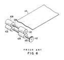
- driving rollers 102 and 104 are mounted on a drive shaft 100
- driven rollers 108 and 110 are mounted on a support shaft 106 so as to correspond to the driving rollers 102 and 104, respectively.
- Torque is transmitted to the drive shaft 100 through a gear train, not shown, and a gear 112 attached to the drive shaft 100 to feed a slip 114 by the sheet feed mechanism.
- Such skew is inferred to be caused by the individual rotation of the driving rollers 102 and 104 and the driven rollers 108 and 108, the difference between the respective radii R1 and R2 (R1 # R2) of the driven rollers 108 and 110, and/or the difference between the respective pressures P1 and P2 (P1 ⁇ P2) of the driving rollers 102 and 104, which are formed of an elastic material, on the slip 114.
- the effects of those causes of skew may be reduced, it is impossible to remove the effects completely, and there is a limit in making the radii R1 and R2 and/or the pressures P1 and P2 accurately equal to each other especially in case of the driving rollers 102 and 104 of small radii.
- a sheet feed mechanism for feeding a sheet comprising: a drive shaft; a plurality of driving rollers mounted on the drive shaft for feeding the sheet; and a single driven roller rotatably disposed opposite to the driving rollers; said driven roller having at least one working surface, corresponding to the working surfaces of the plurality of driving rollers, with either the driving rollers being mounted so as to press the sheet against the driven roller or the driven roller being mounted so as to press the sheet against the driving rollers.
- This sheet feed mechanism has the single driven roller having the working surface corresponding to the driving rollers.
- the driven roller may be of uniform diameter and hence the rotating speed of the working surface of the driven roller is uniform through any point on its working surface.
- the working surfaces of the driven roller can be formed by forming a recessed portion, which does not contact the sheet, on a single roller member, and the working surfaces thus formed respectively corresponding to the driving rollers prevent paper skew.
- the driven roller may be formed by mounting a plurality of rollers to a support shaft (17) and then integrating them into a single roller member so that the plurality of rollers correspond to the driving rollers, respectively, to prevent paper skew.
- a printer provided with this sheet feed mechanism (2) prevents paper skew and is capable of reliable sheet feeding operation and of improving print quality.
- the printer comprises a fixed frame (22), a swing frame (26) and a pressing mechanism, and the driving rollers and the driven roller are mounted on the fixed and the swing frame so as to be disposed opposite to each other, and pressed against each other by the pressing mechanism. Therefore, the printer is capable of preventing paper skew and improve sheet feeding accuracy.
- a sheet feed mechanism 2 in a preferred embodiment according to the present invention comprises a pair of driving rollers 4 and 6, and a single driven roller 8 disposed in combination with the driving rollers 4 and 6.
- the driving rollers 4 and 6 are mounted at a set interval on a drive shaft 10 supported in bearings, not shown.
- a taper surface 12 is formed at one end of each of the driving rollers 4 and 6 to facilitate the insertion of a sheet 14, such as a slip, between the driving rollers 4 and 6, and the driven roller 8.
- a gear 16 is attached to the drive shaft 10 and the output torque of a motor or the like, i.e., a driving source, is transmitted to the gear 16.
- the driven roller 8 is attached to a support shaft 17 supported with its axis in parallel to that of the drive shaft 10.
- the driven roller 8 is an integral member formed of a synthetic resin or the like and having working surfaces 8A and 8B respectively corresponding to the driving rollers 4 and 6 and a recessed portion 18, which does not contact the sheet 14, disposed between the working surfaces 8A and 8B.
- the driven roller 8 may be provided with three or more working surfaces.
- the driven roller 8 may be provided with a single working surface corresponding to the two driving rollers 4 and 6.
- a slip printer in a preferred embodiment according to the present invention is provided with the sheet feed mechanism 2.
- the slip printer has a substantially L-shaped chassis 20, a fixed frame 22, and a swing frame 26 supported by a support shaft 24 on the front end of the chassis 20.
- a printed wiring board 28 and a carriage mechanism 30 are attached to the fixed frame 22, and the driven roller 8 is supported for rotation on a bearing unit 32.
- the carriage mechanism 30 is provided with a carriage motor 34 for driving a carriage 33 carrying a print head 36.
- a feed motor 38, a gear mechanism 40 and a platen 42 are mounted on the swing frame 26.
- the driving rollers 4 and 6 are mounted on the drive shaft 10, and a torque is transmitted through the gear mechanism 40 to the drive shaft 10.
- the driven roller 8 is disposed in combination with the driving rollers 4 and 6 in a position as shown in Fig. 1. In Figs. 1, 2 and 3, like or corresponding parts are designated by the same reference characters.
- the drive shaft 10 and the driving rollers 4 and 6 supported on the swing frame 26, and the driven roller 8 supported on the fixed frame 22 constitute the sheet feed mechanism 2.
- a pressing mechanism 44 for pressing the driving rollers 4 and 6 and the driven roller 8 against each other is disposed between the chassis 20 and the swing frame 26.
- a compression spring 46 is extended between the swing frame 26 and the chassis 20 to bias the swing frame upward so that the driving rollers 4 and 6 are pressed against the working surfaces 8A and 8B of the driven roller 8 with a slip 14 inserted there between.
- a guide plate 48 is mounted on the chassis 20 so as to extend in a space between the fixed frame 22 and the swing frame 26 to guide the slip 14 to the nip line between the driving rollers 4 and 6, and the working surfaces 8A and 8B of the driven roller 8.
- An ink ribbon cassette 50 is mounted on the fixed frame 22.
- An ink ribbon 52 is inserted through the space between the driving rollers 4 and 6 and the driven roller 8 in a space between the print head 38 and the platen 42 so as to be located between the print head 36 and the slip 14.
- the slip 14 is placed on the guide plate 48 with its right edge, as viewed in Fig. 2, in contact with stoppers 54 formed on the guide plate 48. Upon the start of printing operation, the slip 14 is fed by the rotation of the driving rollers 4 and 6.
- the driving rollers 4 and 6 are pressed against the working surfaces 8A and 8B of the driven roller 8 to apply the frictional driving force of the driving rollers 4 and 6 to the slip 14. Since the driven roller 8 is provided integrally with the working surfaces 8A and 8B, and the working surfaces 8A and 8B rotate at the same rotating speed, the slip 14 is fed without a skew in a direction of the arrow M perpendicular to the axis O of the driven roller 8.
- the driven roller is supported on the fixed frame and the driving rollers are supported on the swing frame in this embodiment, the driving rollers and the driven roller may be supported on the fixed frame and the swing frame, respectively.
- the present invention is applicable not only to sheet feed mechanisms but also to sheet ejecting mechanisms.
Landscapes
- Delivering By Means Of Belts And Rollers (AREA)
- Handling Of Continuous Sheets Of Paper (AREA)
- Handling Of Cut Paper (AREA)
- Registering Or Overturning Sheets (AREA)
Claims (6)
- Bahn-Zuführmechanismus (2) zum Zuführen einer Bahn (14), umfassend:
eine Antriebswelle (10); eine Vielzahl von Antriebsrollen (4, 6), die auf der Antriebswelle montiert sind, um die Bahn zuzuführen; und eine einzelne angetriebene Rolle (8), die drehbar gegenüber den Antriebsrollen (4, 6) angeordnet ist; wobei die angetriebene Rolle zumindest eine Arbeitsfläche aufweist, die mit den Arbeitsflächen der Vielzahl von Antriebsrollen (4, 6) korrespondiert, wobei entweder die Antriebsrollen (4, 6) so montiert sind, dass sie die Bahn (14) gegen die angetriebene Rolle (8) pressen, oder die angetriebene Rolle so montiert ist, dass sie die Bahn (14) gegen die Antriebsrollen (4, 6) presst. - Bahn-Zuführmechanismus (2) nach Anspruch 1, wobei die angetriebene Rolle (8) eine Vielzahl von Arbeitsflächen aufweist, die jeweils mit den Arbeitsflächen der Vielzahl von Antriebsrollen (4, 6) korrespondieren.
- Bahn-Zuführmechanismus (2) nach Anspruch 1 oder 2, worin die Arbeitsflächen der angetriebenen Rolle (8) ausgebildet sind, indem an einem einzelnen Rollenelement ein Ausnehmungsabschnitt (18) ausgebildet ist, der die Bahn (14) nicht berührt.
- Bahn-Zuführmechanismus (2) nach Anspruch 1 oder 2, worin die angetriebene Rolle (8) ausgebildet ist, indem eine Vielzahl einzelner Rollen auf einer Stützwelle (17) montiert und diese dann einstückig zu einem einzigen Rollenelement verbunden sind.
- Drucker, bei dem der Bahn-Zuführmechanismus (2) nach Anspruch 1 oder 2 zum Zuführen von Bahnen (14) eingesetzt wird.
- Drucker nach Anspruch 5, umfassend: einen feststehenden Rahmen (22); und einen schwingenden Rahmen (26); wobei die Antriebsrollen (4, 6) und die angetriebene Rolle einander gegenüber auf dem feststehenden Rahmen (22) bzw. dem schwingenden Rahmen (26) oder umgekehrt montiert sind, wobei der Drucker mit einem Andrückmechanismus (44) versehen ist, um die Antriebsrollen (4, 6) und die angetriebenen Rolle (8) gegeneinander gedrückt zu halten.
Applications Claiming Priority (3)
| Application Number | Priority Date | Filing Date | Title |
|---|---|---|---|
| JP7020989A JPH08187906A (ja) | 1995-01-13 | 1995-01-13 | 用紙搬送機構及びプリンタ |
| JP20989/95 | 1995-01-13 | ||
| JP2098995 | 1995-01-13 |
Publications (3)
| Publication Number | Publication Date |
|---|---|
| EP0721846A2 EP0721846A2 (de) | 1996-07-17 |
| EP0721846A3 EP0721846A3 (de) | 1997-07-23 |
| EP0721846B1 true EP0721846B1 (de) | 2000-03-22 |
Family
ID=12042551
Family Applications (1)
| Application Number | Title | Priority Date | Filing Date |
|---|---|---|---|
| EP95309455A Revoked EP0721846B1 (de) | 1995-01-13 | 1995-12-27 | Vorrichtung zum Zuführen eines Blattes und Drucker |
Country Status (6)
| Country | Link |
|---|---|
| US (1) | US5735517A (de) |
| EP (1) | EP0721846B1 (de) |
| JP (1) | JPH08187906A (de) |
| KR (1) | KR960029112A (de) |
| CN (1) | CN1139051A (de) |
| DE (1) | DE69515836T2 (de) |
Families Citing this family (5)
| Publication number | Priority date | Publication date | Assignee | Title |
|---|---|---|---|---|
| DE10350120A1 (de) | 2003-10-28 | 2005-06-09 | Giesecke & Devrient Gmbh | Vorrichtungen zur Bearbeitung von Blattgut |
| JP4892389B2 (ja) * | 2007-04-03 | 2012-03-07 | 株式会社ミマキエンジニアリング | プリンター装置 |
| CN107840165B (zh) * | 2017-12-05 | 2024-08-30 | 深圳市佳博智联软件有限公司 | 用于打印机链式纸的平整装置 |
| CN111634124B (zh) * | 2020-06-11 | 2022-02-22 | 恒科科技产业有限公司 | 一种可防止纸张边缘起皱的打印机轴 |
| JP2023141633A (ja) * | 2022-03-24 | 2023-10-05 | カシオ計算機株式会社 | 印刷装置 |
Family Cites Families (14)
| Publication number | Priority date | Publication date | Assignee | Title |
|---|---|---|---|---|
| US3021134A (en) * | 1959-12-21 | 1962-02-13 | Liberty Folder Company | Adjustable roller hanger for paper folding machines |
| FR2063182A5 (de) * | 1969-09-01 | 1971-07-09 | Samuel Bingham Cy | |
| US3942785A (en) * | 1974-11-25 | 1976-03-09 | Xerox Corporation | Self-actuating sheet inverter reverser |
| JPS57175640A (en) * | 1981-04-21 | 1982-10-28 | Matsushita Electric Ind Co Ltd | Roller unit |
| JPS6019541U (ja) * | 1983-07-19 | 1985-02-09 | 京セラミタ株式会社 | シ−ト部材搬送装置 |
| JPS61197339A (ja) * | 1985-02-27 | 1986-09-01 | Hitachi Ltd | 用紙送り機構 |
| JPH0761725B2 (ja) * | 1986-08-29 | 1995-07-05 | エイ・ティ・アンド・ティ グローバル インフォメーション ソルーションズ インターナショナル インコーポレイテッド | プリンタ |
| JPS63165252A (ja) * | 1986-12-26 | 1988-07-08 | Canon Inc | カ−ル矯正装置 |
| JPS63272733A (ja) * | 1987-04-30 | 1988-11-10 | Tokyo Electric Co Ltd | 用紙送り装置 |
| JPH01285544A (ja) * | 1988-05-12 | 1989-11-16 | Canon Inc | シート材搬送装置 |
| JPH0784080B2 (ja) * | 1988-08-08 | 1995-09-13 | 株式会社日立製作所 | プリンタ |
| US4974680A (en) * | 1988-11-14 | 1990-12-04 | Tokyo Electric Co., Ltd. | Sheet-feeding mechanism |
| JP2801282B2 (ja) * | 1989-09-18 | 1998-09-21 | キヤノン株式会社 | 記録装置 |
| JPH0441268A (ja) * | 1990-06-07 | 1992-02-12 | Seiko Epson Corp | 熱転写プリンタ |
-
1995
- 1995-01-13 JP JP7020989A patent/JPH08187906A/ja active Pending
- 1995-12-27 DE DE69515836T patent/DE69515836T2/de not_active Expired - Fee Related
- 1995-12-27 EP EP95309455A patent/EP0721846B1/de not_active Revoked
- 1995-12-27 US US08/579,293 patent/US5735517A/en not_active Expired - Fee Related
- 1995-12-29 KR KR1019950066686A patent/KR960029112A/ko not_active Abandoned
-
1996
- 1996-01-12 CN CN96104068A patent/CN1139051A/zh active Pending
Also Published As
| Publication number | Publication date |
|---|---|
| EP0721846A2 (de) | 1996-07-17 |
| JPH08187906A (ja) | 1996-07-23 |
| DE69515836D1 (de) | 2000-04-27 |
| KR960029112A (ko) | 1996-08-17 |
| EP0721846A3 (de) | 1997-07-23 |
| CN1139051A (zh) | 1997-01-01 |
| US5735517A (en) | 1998-04-07 |
| DE69515836T2 (de) | 2000-10-12 |
Similar Documents
| Publication | Publication Date | Title |
|---|---|---|
| EP0581276B1 (de) | Blattfördervorrichtung | |
| EP0609560B1 (de) | Bogenförderapparat | |
| JP2545362Y2 (ja) | 自動給紙装置 | |
| US5735517A (en) | Sheet feed mechanism and printer | |
| JPS588680A (ja) | 印字装置の用紙クランプ装置 | |
| KR0166459B1 (ko) | 열전사식 프린터 | |
| US4693620A (en) | Variable width paper feeder for perforated and unperforated paper | |
| US5050858A (en) | Sheet feed control method | |
| US4632380A (en) | Paper feeding apparatus | |
| US6017160A (en) | Printer sheet feed device having controller | |
| JP2707228B2 (ja) | プリンタの紙送りロール駆動装置 | |
| JP2787035B2 (ja) | プリンタの紙ガイド装置 | |
| JPS6010998Y2 (ja) | ピンチロ−ラ機構 | |
| JPH0414634B2 (de) | ||
| JPS6364779A (ja) | 用紙給送装置 | |
| KR20030059560A (ko) | 잉크젯 프린터의 드라이브롤러 해제장치 | |
| JPH0649562Y2 (ja) | 給紙装置 | |
| JP3142147B2 (ja) | プリンタの紙送り機構 | |
| JP2853234B2 (ja) | 印字装置における紙送り機構 | |
| JP2794694B2 (ja) | 紙送り機構 | |
| JP2949028B2 (ja) | 処理済マークの押印装置 | |
| JPS6312112Y2 (de) | ||
| JP3069488U (ja) | プリンタ | |
| JP2505638Y2 (ja) | プリンタにおける印字媒体給送機構 | |
| JPH10258532A (ja) | 感熱式プリンタ |
Legal Events
| Date | Code | Title | Description |
|---|---|---|---|
| PUAI | Public reference made under article 153(3) epc to a published international application that has entered the european phase |
Free format text: ORIGINAL CODE: 0009012 |
|
| AK | Designated contracting states |
Kind code of ref document: A2 Designated state(s): DE GB |
|
| PUAL | Search report despatched |
Free format text: ORIGINAL CODE: 0009013 |
|
| AK | Designated contracting states |
Kind code of ref document: A3 Designated state(s): DE GB |
|
| 17P | Request for examination filed |
Effective date: 19971021 |
|
| GRAG | Despatch of communication of intention to grant |
Free format text: ORIGINAL CODE: EPIDOS AGRA |
|
| 17Q | First examination report despatched |
Effective date: 19981124 |
|
| GRAG | Despatch of communication of intention to grant |
Free format text: ORIGINAL CODE: EPIDOS AGRA |
|
| GRAG | Despatch of communication of intention to grant |
Free format text: ORIGINAL CODE: EPIDOS AGRA |
|
| GRAH | Despatch of communication of intention to grant a patent |
Free format text: ORIGINAL CODE: EPIDOS IGRA |
|
| GRAH | Despatch of communication of intention to grant a patent |
Free format text: ORIGINAL CODE: EPIDOS IGRA |
|
| GRAA | (expected) grant |
Free format text: ORIGINAL CODE: 0009210 |
|
| AK | Designated contracting states |
Kind code of ref document: B1 Designated state(s): DE GB |
|
| REF | Corresponds to: |
Ref document number: 69515836 Country of ref document: DE Date of ref document: 20000427 |
|
| EN | Fr: translation not filed | ||
| PG25 | Lapsed in a contracting state [announced via postgrant information from national office to epo] |
Ref country code: GB Free format text: LAPSE BECAUSE OF NON-PAYMENT OF DUE FEES Effective date: 20001227 |
|
| PLBE | No opposition filed within time limit |
Free format text: ORIGINAL CODE: 0009261 |
|
| PLBQ | Unpublished change to opponent data |
Free format text: ORIGINAL CODE: EPIDOS OPPO |
|
| PLAA | Information modified related to event that no opposition was filed |
Free format text: ORIGINAL CODE: 0009299DELT |
|
| PLBI | Opposition filed |
Free format text: ORIGINAL CODE: 0009260 |
|
| PLBF | Reply of patent proprietor to notice(s) of opposition |
Free format text: ORIGINAL CODE: EPIDOS OBSO |
|
| 26N | No opposition filed | ||
| 26 | Opposition filed |
Opponent name: SPANDERN, UWE Effective date: 20001222 |
|
| D26N | No opposition filed (deleted) | ||
| RDAH | Patent revoked |
Free format text: ORIGINAL CODE: EPIDOS REVO |
|
| GBPC | Gb: european patent ceased through non-payment of renewal fee |
Effective date: 20001227 |
|
| DX | Miscellaneous (deleted) | ||
| RDAG | Patent revoked |
Free format text: ORIGINAL CODE: 0009271 |
|
| STAA | Information on the status of an ep patent application or granted ep patent |
Free format text: STATUS: PATENT REVOKED |
|
| 27W | Patent revoked |
Effective date: 20010830 |