EP0722832A2 - Verbesserungen in oder bezüglich des Druckens - Google Patents
Verbesserungen in oder bezüglich des Druckens Download PDFInfo
- Publication number
- EP0722832A2 EP0722832A2 EP96300398A EP96300398A EP0722832A2 EP 0722832 A2 EP0722832 A2 EP 0722832A2 EP 96300398 A EP96300398 A EP 96300398A EP 96300398 A EP96300398 A EP 96300398A EP 0722832 A2 EP0722832 A2 EP 0722832A2
- Authority
- EP
- European Patent Office
- Prior art keywords
- ink
- temperature
- printing
- air
- controlling device
- Prior art date
- Legal status (The legal status is an assumption and is not a legal conclusion. Google has not performed a legal analysis and makes no representation as to the accuracy of the status listed.)
- Withdrawn
Links
Images
Classifications
-
- B—PERFORMING OPERATIONS; TRANSPORTING
- B41—PRINTING; LINING MACHINES; TYPEWRITERS; STAMPS
- B41F—PRINTING MACHINES OR PRESSES
- B41F31/00—Inking arrangements or devices
- B41F31/002—Heating or cooling of ink or ink rollers
Definitions
- This invention relates to printing and is concerned with the control of ink temperature during printing.
- Rotary printing presses are known to include a plate cylinder upon which is mounted a printing plate carrying a printing image.
- An inking system is provided to convey ink from an ink source to the plate cylinder whereby ink is applied to the printing image.
- the ink is then transferred from the printing image to the substrate to be printed, in the case of offset printing, via the intermediary of a resilient blanket.
- water is additionally applied to the printing plate.
- a dry offset printing process is known which has the advantage that the application of water is avoided. In order for dry offset printing to be successfully carried out, it is necessary to control the temperature of the ink.
- the inking system includes an inking train comprising several inking rollers with one or more inking rollers running in contact with the plate cylinder. It is known to control the temperature of the ink by circulating water through the central core of some of the inking rollers.
- this technique is not very responsive in that it takes a considerable time for the water passing through the inking roller to cause a variation in the temperature of the ink.
- this technique merely controls the temperature of the ink on the inking roller whereas it is the temperature of the ink as it is being applied to the paper which needs to be regulated.
- the requirement to conduct water through the inking roller to control the ink temperature introduces an additional cost which is disadvantageous.
- one aspect of the present invention provides an ink temperature controlling device in, or for use in, a printing press comprising a plate cylinder, a printing plate mounted on the plate cylinder and having a printing image, and an inking roller for applying ink to the printing image for subsequent application to the substrate to be printed, characterised in that the ink temperature controlling device comprises a means of directing air of controlled temperature at the ink.
- a method of controlling the temperature of ink during printing of a substrate which method comprises directing air of controlled temperature at the ink so that the ink applied to the substrate has a desired temperature.
- the temperature of the air may be somewhat less than ambient temperature as a consequence of its movement.
- the air emanating from the device is at ambient temperature or elevated temperature and the temperature of the ink is controlled solely by the air emanating from the device. More particularly, no water or other liquid is circulated through an inking roller to adjust the temperature of the ink on the inking train.
- the ink temperature control device comprises a fan adapted to receive air from the atmosphere and propel it to the ink on the printing image and/or printing blanket and/or inking roller with the assistance of a suitable heater when necessary.
- the fan is of the axial type and the heater incorporates a heating element and a thermistor whereby the temperature of the heating element can be varied.
- a means of varying the speed of the fan may also be provided.
- the air being introduced into the fan is filtered-so as to prevent dust contaminating the ink.
- the temperature of the ink is monitored by, for example, an optical sensor. Then the temperature and/or volume of air being directed at the ink from the device can be manually controlled as desired in order to ensure that the ink is at a desired temperature.
- the sensor may be operably connected to the ink temperature control device to form a closed loop system whereby the temperature and/or speed of the air flow is automatically varied in dependence on the sensed temperature so that the ink temperature is kept at a desired temperature. Generally, it is preferred to maintain the air speed constant and to regulate the ink temperature by adjustment of the temperature of the air.
- the printing press is an offset press (either dry offset or offset lithographic) including a blanket cylinder and an impression cylinder so that ink is transferred from the printing plate to the blanket and hence to the substrate to be printed.
- the device is preferably located so as to direct the air at the vicinity of the nip between the plate cylinder and the blanket cylinder.
- the ink temperature control device may include more than one fan, heater and filter located transversely across the press.
- the temperature of the heaters and/or the speed of the fans may be controlled together but, if desired, each heater and/or fan may be individually controlled to provide different heating or cooling affects across the width of the press.
- each unit may be provided with one or more ink temperature controlling devices in accordance with the present invention.
- the device(s) of each printing unit will preferably be independently controllable so as to achieve an ink temperature appropriate to the nature of the ink being used at that unit.
- the device In use, the device is located to direct heated air at the ink on, for example, the plate cylinder at start up until the ink reaches the desired temperature. Then, as printing commences, and heat is generated by the printing press, the heating element may be switched off so that the device merely directs air at ambient temperature onto the ink. In this way, an adequate control of temperature can generally be achieved.
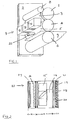
- a printing press comprising a plate cylinder 1 rotatably mounted in side frames (of which one only is shown and denoted by reference numeral 2).
- a printing plate 3 having a printing image (not shown) is fitted on the plate cylinder 1.
- the printing press also includes a blanket cylinder 4 carrying a resilient blanket 5 and similarly mounted for rotation in the side frames.
- the blanket cylinder 4 is positioned so as to form a nip with the plate cylinder 1.
- the press includes an impression cylinder 6 rotatably mounted in the side frames so as to form a nip with the blanket cylinder 4.
- the substrate 7 to be printed e.g. a paper sheet, passes through the nip between the blanket cylinder 4 and the impression cylinder 6.
- Ink is applied to the printing image on the printing plate 3 by means of an inking roller 8 rotatably mounted in the side frames in contact with the plate cylinder so as to convey ink from a source (not shown) to the printing plate 3.
- An ink-temperature control device 9 is mounted facing the printing plate and printing blanket nip and extends across the width of the printing press.
- the device 9 includes a plurality of modules 10 (three being shown in the drawing) each including a fan unit 11, a heater unit 12 and a filter unit 13 (see Figure 2) arranged so that each fan unit 11 draws air into the device, through its associated filter unit 13, from the atmosphere and expels the air from the device via its associated heater unit 12.
- Each fan unit 11 includes an electric motor 14 driving fan blades 15. Typically it may be of the type supplied by Papst and available from RS Components Ltd under their stock No.508-059. This is of all metal construction and is an axial 24V fan.
- Each heater unit 12 is controllable and includes a heating element 16 operably connected to a positive temperature coefficient element 17 whereby the output of the heating element may be regulated.
- the heater unit may be of the type available from RS Components Ltd under their stock No.224-565.
- Each filter unit 13 includes a suitable filter element and may be of the type available from RS Components Ltd under their stock No.221-242. This comprises a cover 18, a mesh 19 and a finger guard 20 moulded in nylon resin and a filter pad 21 formed from polyester.
- the heater units 12 are operably connected to an optical sensor 22 adapted to monitor the temperature of the ink on the blanket immediately before it contacts the substrate 7.
- the sensor 22 may, alternatively, be located so as to monitor the temperature of the ink on the printing plate.
- the fan and heater units are switched on so that air at elevated temperature is directed at the ink on the printing plate and blanket to heat it to such a temperature that the ink, which is about to be transferred to the substrate is at a desired temperature.
- the sensor 22 transmits a signal to the device so as to switch off the heater units 12. Should the temperature of the ink drop below the desired temperature, this is sensed by the sensor 22 and the heater units are switched on again.
- heat is generated and it is not normally necessary to continue to supply heat to the ink from the heater units of the device.
- the ink needs to be cooled so as not to exceed the desired temperature and this is effected by using the device to blow air at ambient temperature onto the ink.
- the device of the invention can be readily fitted to new and existing printing presses at no great expense and is itself inexpensive to produce.
- the printing press shown in the drawings is a dry offset press
- the invention can be similarly applied to an offset lithographic printing press.
Landscapes
- Inking, Control Or Cleaning Of Printing Machines (AREA)
- Control Of Temperature (AREA)
Applications Claiming Priority (2)
| Application Number | Priority Date | Filing Date | Title |
|---|---|---|---|
| GBGB9501272.0A GB9501272D0 (en) | 1995-01-23 | 1995-01-23 | Improvements in or relating to printing |
| GB9501272 | 1995-01-23 |
Publications (2)
| Publication Number | Publication Date |
|---|---|
| EP0722832A2 true EP0722832A2 (de) | 1996-07-24 |
| EP0722832A3 EP0722832A3 (de) | 1996-07-31 |
Family
ID=10768414
Family Applications (1)
| Application Number | Title | Priority Date | Filing Date |
|---|---|---|---|
| EP96300398A Withdrawn EP0722832A3 (de) | 1995-01-23 | 1996-01-22 | Verbesserungen in oder bezüglich des Druckens |
Country Status (6)
| Country | Link |
|---|---|
| US (1) | US5810927A (de) |
| EP (1) | EP0722832A3 (de) |
| JP (1) | JPH08238751A (de) |
| AU (1) | AU701787B2 (de) |
| CA (1) | CA2167769A1 (de) |
| GB (1) | GB9501272D0 (de) |
Cited By (2)
| Publication number | Priority date | Publication date | Assignee | Title |
|---|---|---|---|---|
| US6699328B1 (en) * | 1999-08-07 | 2004-03-02 | Man Roland Druckmaschinen Ag | Device for the temperature equalisation of coating media |
| EP3059083A1 (de) * | 2008-04-11 | 2016-08-24 | O-PAC S.r.l. | Maschine zur linearen transformation von mit gefärbten wachsen und paraffinen wärmebedruckten einwegprodukten |
Families Citing this family (5)
| Publication number | Priority date | Publication date | Assignee | Title |
|---|---|---|---|---|
| JPH08295009A (ja) * | 1995-04-27 | 1996-11-12 | Mitsubishi Heavy Ind Ltd | フレキソ印刷機 |
| DE19937468A1 (de) * | 1999-08-07 | 2001-03-08 | Roland Man Druckmasch | Vorrichtung zum Temperieren von Beschichtungsmedien |
| EP1600290B1 (de) * | 2001-11-22 | 2006-08-23 | Koenig & Bauer Aktiengesellschaft | Verwendung einer Druckfarbe in einem Druckwerk |
| EP1415805A1 (de) | 2002-10-28 | 2004-05-06 | Hauni Maschinenbau AG | Druckwerk mit Temperiereinrichtung |
| JP5943867B2 (ja) * | 2013-03-26 | 2016-07-05 | 富士フイルム株式会社 | 印刷装置及び印刷方法 |
Family Cites Families (12)
| Publication number | Priority date | Publication date | Assignee | Title |
|---|---|---|---|---|
| DE851954C (de) * | 1949-12-07 | 1952-10-09 | Rudolf Mueller | Verfahren zur Herstellung einer satten Farbflaeche und eines feuchtigkeitsfreien Druckes bei Offsetmaschinen |
| FR1014725A (fr) * | 1950-03-16 | 1952-08-20 | Prografin G M B H | Appareil à refroidir les cylidres encreurs en couleur des presses d'imprimerie pendant l'impression |
| US3813516A (en) * | 1969-12-29 | 1974-05-28 | Ibm | Apparatus for temperature control for a heated rotating cylinder |
| US4341156A (en) * | 1980-08-28 | 1982-07-27 | Cip Inc. | Dilitho printing image heating |
| US4693179A (en) * | 1984-12-10 | 1987-09-15 | Lockwood Technical, Inc. | Temperature controlled rotary screen printing apparatus |
| JPH0630929B2 (ja) * | 1985-09-04 | 1994-04-27 | キヤノン株式会社 | インクジェットプリンタ |
| DE3541458A1 (de) * | 1985-11-23 | 1987-05-27 | Koenig & Bauer Ag | Kurzfarbwerk fuer offsetrotationsdruckmaschinen |
| DE3925034C1 (de) * | 1989-07-28 | 1990-08-09 | Man Roland Druckmaschinen Ag, 6050 Offenbach, De | |
| US5168811A (en) * | 1990-09-20 | 1992-12-08 | Csb Corporation | Method and apparatus for accelerating setting and drying of liquid media |
| DE4202544A1 (de) * | 1992-01-30 | 1993-08-05 | Baldwin Gegenheimer Gmbh | Druckplatten-temperierungssystem fuer eine druckmaschine |
| DE4217813C2 (de) * | 1992-05-29 | 1996-06-05 | Heidelberger Druckmasch Ag | Vorrichtung zum Erzielen einer flächigen Anlage von Bedruckstoffen |
| US5272971A (en) * | 1992-08-14 | 1993-12-28 | Electro Sprayer Systems, Inc. | Ink temperature control system for waterless lithographic printing |
-
1995
- 1995-01-23 GB GBGB9501272.0A patent/GB9501272D0/en active Pending
-
1996
- 1996-01-22 JP JP8008738A patent/JPH08238751A/ja active Pending
- 1996-01-22 CA CA002167769A patent/CA2167769A1/en not_active Abandoned
- 1996-01-22 US US08/589,623 patent/US5810927A/en not_active Expired - Fee Related
- 1996-01-22 AU AU42085/96A patent/AU701787B2/en not_active Ceased
- 1996-01-22 EP EP96300398A patent/EP0722832A3/de not_active Withdrawn
Cited By (2)
| Publication number | Priority date | Publication date | Assignee | Title |
|---|---|---|---|---|
| US6699328B1 (en) * | 1999-08-07 | 2004-03-02 | Man Roland Druckmaschinen Ag | Device for the temperature equalisation of coating media |
| EP3059083A1 (de) * | 2008-04-11 | 2016-08-24 | O-PAC S.r.l. | Maschine zur linearen transformation von mit gefärbten wachsen und paraffinen wärmebedruckten einwegprodukten |
Also Published As
| Publication number | Publication date |
|---|---|
| JPH08238751A (ja) | 1996-09-17 |
| EP0722832A3 (de) | 1996-07-31 |
| AU701787B2 (en) | 1999-02-04 |
| US5810927A (en) | 1998-09-22 |
| AU4208596A (en) | 1996-08-01 |
| GB9501272D0 (en) | 1995-03-15 |
| CA2167769A1 (en) | 1996-07-24 |
Similar Documents
| Publication | Publication Date | Title |
|---|---|---|
| JP2877705B2 (ja) | 無水オフセット印刷のための印刷機械 | |
| US6877247B1 (en) | Power saving automatic zoned dryer apparatus and method | |
| JP3027144B2 (ja) | ロール紙輪転印刷機の連続印刷状態達成方法 | |
| US20020112636A1 (en) | Process temperature control system for rotary process machinery | |
| US5810927A (en) | Ink temperature control | |
| US5178064A (en) | Thermal regulator for a printing form laid about a printing form cylinder for anaqueous offset printing | |
| JPH0235667B2 (de) | ||
| US6283590B1 (en) | Liquid ink printer including a non-scorching dryer assembly | |
| JP2003237036A (ja) | 画像形成装置 | |
| JP2867755B2 (ja) | 印字装置 | |
| US6698958B2 (en) | Sublimation system and method | |
| JP5112667B2 (ja) | 印刷機の温度を調節する方法 | |
| JP2003237034A (ja) | 画像形成装置 | |
| US5894795A (en) | Apparatus and method for preventing condensation in machines processing a web of material | |
| JP3312573B2 (ja) | 湿し水制御装置および印刷機 | |
| JP2640233B2 (ja) | スリツタマシン | |
| GB2063168A (en) | Printing unit with heater for reducing register differences on startup | |
| JP2626793B2 (ja) | スリッタマシン | |
| US5513569A (en) | Method of controlling a start-up of paper travel in a printing press | |
| JPH0528635U (ja) | 印刷機のインキ装置 | |
| JP2930385B2 (ja) | 湿し水制御装置 | |
| JP2505633Y2 (ja) | 自動スクリ―ン捺染機の加熱装置 | |
| JPH04235080A (ja) | 熱転写式印字装置 | |
| JP2537502Y2 (ja) | 印刷ユニツトの温度調整装置 | |
| JPH05193115A (ja) | インキ供給装置 |
Legal Events
| Date | Code | Title | Description |
|---|---|---|---|
| PUAI | Public reference made under article 153(3) epc to a published international application that has entered the european phase |
Free format text: ORIGINAL CODE: 0009012 |
|
| PUAL | Search report despatched |
Free format text: ORIGINAL CODE: 0009013 |
|
| AK | Designated contracting states |
Kind code of ref document: A2 Designated state(s): AT BE CH DE DK ES FR GB GR IE IT LI LU MC NL PT SE |
|
| AK | Designated contracting states |
Kind code of ref document: A3 Designated state(s): AT BE CH DE DK ES FR GB GR IE IT LI LU MC NL PT SE |
|
| 17P | Request for examination filed |
Effective date: 19970129 |
|
| 17Q | First examination report despatched |
Effective date: 19970922 |
|
| RAP1 | Party data changed (applicant data changed or rights of an application transferred) |
Owner name: FRANK BALL LTD. Owner name: AYRES, JOHN |
|
| GRAG | Despatch of communication of intention to grant |
Free format text: ORIGINAL CODE: EPIDOS AGRA |
|
| STAA | Information on the status of an ep patent application or granted ep patent |
Free format text: STATUS: THE APPLICATION IS DEEMED TO BE WITHDRAWN |
|
| 18D | Application deemed to be withdrawn |
Effective date: 20000731 |