EP0723263A1 - Optisches Abtastgerät für eine magnetooptische Platte - Google Patents
Optisches Abtastgerät für eine magnetooptische Platte Download PDFInfo
- Publication number
- EP0723263A1 EP0723263A1 EP95100424A EP95100424A EP0723263A1 EP 0723263 A1 EP0723263 A1 EP 0723263A1 EP 95100424 A EP95100424 A EP 95100424A EP 95100424 A EP95100424 A EP 95100424A EP 0723263 A1 EP0723263 A1 EP 0723263A1
- Authority
- EP
- European Patent Office
- Prior art keywords
- wave
- optical
- polarized beam
- optical disk
- magneto
- Prior art date
- Legal status (The legal status is an assumption and is not a legal conclusion. Google has not performed a legal analysis and makes no representation as to the accuracy of the status listed.)
- Withdrawn
Links
- 230000003287 optical effect Effects 0.000 title claims abstract description 93
- 230000010287 polarization Effects 0.000 claims abstract description 9
- 230000003247 decreasing effect Effects 0.000 abstract description 2
- 201000009310 astigmatism Diseases 0.000 description 2
- 238000010276 construction Methods 0.000 description 2
- 230000005415 magnetization Effects 0.000 description 2
- 238000004519 manufacturing process Methods 0.000 description 2
- 230000035945 sensitivity Effects 0.000 description 2
- 238000010586 diagram Methods 0.000 description 1
- 230000000694 effects Effects 0.000 description 1
Images


Classifications
-
- G—PHYSICS
- G11—INFORMATION STORAGE
- G11B—INFORMATION STORAGE BASED ON RELATIVE MOVEMENT BETWEEN RECORD CARRIER AND TRANSDUCER
- G11B11/00—Recording on or reproducing from the same record carrier wherein for these two operations the methods are covered by different main groups of groups G11B3/00 - G11B7/00 or by different subgroups of group G11B9/00; Record carriers therefor
- G11B11/10—Recording on or reproducing from the same record carrier wherein for these two operations the methods are covered by different main groups of groups G11B3/00 - G11B7/00 or by different subgroups of group G11B9/00; Record carriers therefor using recording by magnetic means or other means for magnetisation or demagnetisation of a record carrier, e.g. light induced spin magnetisation; Demagnetisation by thermal or stress means in the presence or not of an orienting magnetic field
- G11B11/105—Recording on or reproducing from the same record carrier wherein for these two operations the methods are covered by different main groups of groups G11B3/00 - G11B7/00 or by different subgroups of group G11B9/00; Record carriers therefor using recording by magnetic means or other means for magnetisation or demagnetisation of a record carrier, e.g. light induced spin magnetisation; Demagnetisation by thermal or stress means in the presence or not of an orienting magnetic field using a beam of light or a magnetic field for recording by change of magnetisation and a beam of light for reproducing, i.e. magneto-optical, e.g. light-induced thermomagnetic recording, spin magnetisation recording, Kerr or Faraday effect reproducing
- G11B11/10532—Heads
- G11B11/10541—Heads for reproducing
- G11B11/10543—Heads for reproducing using optical beam of radiation
- G11B11/10545—Heads for reproducing using optical beam of radiation interacting directly with the magnetisation on the record carrier
Definitions
- the present invention relates to an optical pickup for recording/reading out information on/from a magneto-optical disk, and more particularly to an optical pickup apparatus of a magneto-optical disk for realizing lightweight pickup and improving read-out speed by accurately detecting focusing and tracking errors and by decreasing bulky optical system and the need of many component numbers thereof, using a modified polarized beam divider and a single optical detector.
- an optical pickup apparatus of a conventional magneto-optical disk includes a laser diode 1 for emitting a laser beam and a collimator lens 2 for allowing the laser beam emitted from the laser diode 1 to be parallel rays.
- a first polarized beam divider 3 linearly polarizes the parallel rays via the collimator lens 2 to be P wave, and is provided with a first boundary plane 3a that reflects all S wave and partial P wave of the beam reflected from an optical disk 5 and transmits remaining P wave.
- An objective lens 4 focuses the P wave linearly polarized via the first polarized beam divider 3 onto the optical disk 5.
- a half wave plate 6 receives all S wave and partial P wave reflected by the first boundary plane 3a of the first polarized beam divider 3 to rotate the polarization direction by 45°.
- a second polarized beam divider 7 separates the beam which has been rotated by 45° via the half wave plate 6 into the S wave and P wave to reflect all S wave by means of a second boundary plane 7a thereof and to transmit all P wave.
- a cylindrical lens 8 induces astigmatism to the S wave reflected by the second boundary plane 7a of the second polarized beam divider 7, and first and second optical detectors 9 and 10 detect a focusing error and optical information by the incident beam of the S wave focused by the cylindrical lens 8 and the P wave having passed through the second polarized beam divider 7.
- the laser beam emitted from the laser diode 1 becomes the parallel rays via the collimator lens 2 to thereby be incident to the first polarized beam divider 3.
- the laser beam transformed to be the parallel rays via the collimator lens 2 is linearly polarized to be the P wave, and then focused onto the optical disk 5 via the objective lens 4.
- the beam of P wave focused onto the optical disk 5 is used for reading out information and detecting a servo signal.
- the beam of P wave is reflected from the optical disk 5 while being incorporated with the information (i.e,, pit information or information which is elliptically polarized by magnetization direction ⁇ recorded on the optical disk 5, and again becomes the parallel rays via the objective lens 4 to be incident to the first polarized beam divider 3.
- the S wave is generated by the elliptical polarization by the recorded information.
- the S wave is mixed with the P wave to be incident to the first polarized beam divider 3.
- the optical disk 5 has the information thereon, all S wave and partial P wave incident to the first polarized beam divider 3 are reflected by the first boundary plane 3a of the first polarized beam divider 3 to be incident to the half wave plate 6.
- the beam of S wave and P wave reflected from the first polarized beam divider 3 is rotated by 45° in the polarization direction via the half wave plate 6 to maximize the sensitivity of a magneto-optical signal.
- the beam having the S wave and P wave mixed with each other via the half wave plate 6 is separated into the S wave and P wave, so that the all S wave is reflected by the second boundary plane 7a to be incident to the cylindrical lens 8 and all P wave passes through the second polarized beam divider 7 to be incident to the second optical detector 10.
- the beam of S wave reflected from the second boundary plane 7a of the second polarized beam divider 7 is focused via the cylindrical lens 8 which generates the astigmatism for detecting a focus error signal to be incident to the first optical detector 9.
- the first and second optical detectors 9 and 10 detect an optical information signal (i.e., the magneto-optical signal) by means of a signal difference between the beams of S wave and P wave which are respectively incident to divided regions via the cylindrical lens 8 and second polarized beam divider 7.
- an optical information signal i.e., the magneto-optical signal
- the optical information signal (pit information) is sensed by the variation of optical amount of Sa + Pa.
- the focusing error and tracking error are monitored by the first optical detector 9 divided-by-four or -six.
- the optical pickup apparatus of the conventional magneto-optical disk employs the cylindrical lens which is inherently expensive and fastidious in its fabrication, and the optical detector thereof is independently separated into two parts to read out the information.
- the cylindrical lens which is inherently expensive and fastidious in its fabrication
- the optical detector thereof is independently separated into two parts to read out the information.
- such an optical system structure increases the number of optical components which in turn expands space occupied, thereby lowering read-out speed resulting from the increase of the pickup weight as well as heightening manufacturing cost.
- an optical pickup apparatus of a magneto-optical disk a laser beam from a laser diode is focused onto an optical disk via a collimator lens, a first polarized beam divider and an objective lens, processed to be S and P waves in the reverse order of the focusing, and reflected by the first polarized beam divider to be incident to a half wave plate.
- the half wave plate rotates the polarization direction of all S wave and partial P wave by 45°
- a second polarized beam divider separates the beam via the half wave plate into S wave and P wave to be outgoing in the same direction
- an optical detector divided-by-eight detects the tracking error, focusing error and optical information signal by using a sum or difference signal of the S wave and P wave reflected by the second polarized beam divider.
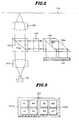
- an optical pickup apparatus of a magneto-optical disk has a laser diode 100 for omitting a laser beam, and a collimator lens 101 for allowing the laser beam emitted from the laser diode 100 to be parallel rays.
- a first polarized beam divider 102 linearly polarizes the parallel rays to P wave, and includes a first boundary plane 102a for reflecting all S wave and partial P wave of the beam reflected from an optical disk 104.
- An objective lens 103 focuses the P wave linearly polarized by the first polarized beam divider 102 onto the optical disk 104.
- a half wave plate 105 allows the reflected beam to be parallel rays again via the objective lens 103 in accordance with the existence of information on the optical disk 104, and rotates all S wave and partial P wave incident thereto after being reflected from the boundary plane 102a of the first polarized beam divider 102 by 45°.
- a second polarized beam divider 106 separates the incident beam via the half wave plate 105 into S wave and P wave to be outgoing in the same direction, and an optical detector 107 divided-by-eight detects a tracking error, a focusing error and an optical information signal by means of a sum or difference signal of the S wave and P wave which are outgoing from the second polarized beam divider 106 to focus onto every region.
- the second polarized beam divider 106 is formed in such a manner that a right isosceles triangular prism and a parallelogram prism having an angle of 45° are combined, and a boundary plane 106a of them is coated to separate the polarized beam. Therefore, the S wave is fully reflected to the optical detector 107, the P wave is fully transmitted, and an oblique side 106b of the parallelogram prism fully reflects the P wave having passed through the boundary plane 106a.
- the optical detector 107 is separately formed of a first detecting region 107a divided into first to fourth areas A1 to A4 for detecting the beam of S wave reflected by the boundary plane 106a of the second polarized beam divider 106, and a second detecting region 107b divided into fifth to eighth areas A5 to A8 for detecting the beam of P wave reflected from the oblique side 106b of the second polarized beam divider 106.
- the laser beam emitted from the laser diode 100 becomes the parallel rays via the collimator lens 101 to be incident to the first polarized beam divider 102.
- the laser beam transformed into the parallel rays via the collimator lens 101 is linearly polarized to the P wave through the first polarized beam divider 102, and then focusing onto the optical disk 104 through the objective lens 103.
- the beam of P wave is reflected from the optical disk 104 while containing the information (i.e., pit information or information which is elliptically polarized by the magnetization direction) recorded on the optical disk 104, and again changed into the parallel rays via the objective lens 103 to be incident to the first polarized beam divider 102.
- the S wave is generated by an elliptical polarization of the recorded information.
- the S wave is mixed with the P wave to be incident to the first polarized beam divider 102.
- the only P wave is incident to the first polarized beam divider 102.
- all S wave and partial P wave incident to the first polarized beam divider 102 are reflected by the first boundary plane 102a of the first polarized beam divider 102 to be linearly polarized, thereby being incident to the half wave plate 105.
- the polarization direction of the beam of S wave and P wave reflected by the first polarized beam divider 102 is rotated by 45° via the half wave plate 105 to maximally correct a magneto-optical signal.
- the beam of S wave mixed with P wave having the polarized angle of 45° rotated by the half wave plate 105 is incident to the second polarized beam divider 106.
- the second polarized beam divider 106 formed by combining the right isosceles triangular prism and the parallelogram prism having an angle of 45° has the polarization-coated boundary plane 106a to fully reflect the S wave and to fully transmit the P wave, which are incident thereto.
- the optical detector 107 detects the optical information signal S MO , tracking error signal TES and focusing error signal FES by means of the sum or difference signal of the beam of S wave incident to the first detecting region 107a and the beam of P wave incident to the second detecting region 107b.
- the optical information signal i.e., the magneto-optical signal
- S MO the optical information signal
- the focusing error signal FES can be obtained by the signal difference of the S wave and P wave focusing onto the first to eighth areas A1 to A8 of the optical detector 107 in view of the threshold angle rule in accordance with the changes distance between the optical disk 104 and objective lens 103.
- the beam sizes obtained in the first and second detecting regions 107a and 107b are different from each other: i.e., the beam size of the first detecting region is larger than that of the second detecting region in case of FIG. 4B, and that of the first detecting region is smaller than the second detecting region in case of FIG. 4C.
- the optical information signal, tracking error signal and focusing error signal are obtained by equations 1, 2 and 3, so that the focusing and tracking can be adjusted by moving the objective lens 103 up-and-down or right-to-left direction by means of an actuator (not shown) when the focusing and tracking are not correct.
- An optical pickup apparatus of a magneto-optical disk according to the present invention as described above adopts a modified polarized beam divider and a single optical detector to accurately detect a focusing error, a tracking error and a magneto-optical signal recorded on a disk while reducing the number and weight of optical system components, thereby attaining a light-weight pickup and improving read-out speed. Furthermore, the modified polarized beam divider is employed to obtain a focusing error signal by using a threshold angle rule with respect to P wave and S wave, respectively, which in turn enhances sensitivity.
Priority Applications (1)
| Application Number | Priority Date | Filing Date | Title |
|---|---|---|---|
| EP95100424A EP0723263A1 (de) | 1995-01-13 | 1995-01-13 | Optisches Abtastgerät für eine magnetooptische Platte |
Applications Claiming Priority (1)
| Application Number | Priority Date | Filing Date | Title |
|---|---|---|---|
| EP95100424A EP0723263A1 (de) | 1995-01-13 | 1995-01-13 | Optisches Abtastgerät für eine magnetooptische Platte |
Publications (1)
| Publication Number | Publication Date |
|---|---|
| EP0723263A1 true EP0723263A1 (de) | 1996-07-24 |
Family
ID=8218902
Family Applications (1)
| Application Number | Title | Priority Date | Filing Date |
|---|---|---|---|
| EP95100424A Withdrawn EP0723263A1 (de) | 1995-01-13 | 1995-01-13 | Optisches Abtastgerät für eine magnetooptische Platte |
Country Status (1)
| Country | Link |
|---|---|
| EP (1) | EP0723263A1 (de) |
Cited By (2)
| Publication number | Priority date | Publication date | Assignee | Title |
|---|---|---|---|---|
| EP0924696A1 (de) * | 1997-12-18 | 1999-06-23 | Deutsche Thomson-Brandt Gmbh | Verfahren zur Korrektur des Spurfolgesignals während der Wiedergabe einer optischen Platte |
| CN111829954A (zh) * | 2020-09-09 | 2020-10-27 | 广东工业大学 | 一种提高全场扫频光学相干层析测量量程的系统及方法 |
Citations (5)
| Publication number | Priority date | Publication date | Assignee | Title |
|---|---|---|---|---|
| DE3802538A1 (de) * | 1987-01-28 | 1988-08-11 | Olympus Optical Co | Vorrichtung zum erfassen von fotomagnetischen signalen |
| EP0439876A1 (de) * | 1990-01-29 | 1991-08-07 | Hitachi Maxell Ltd. | Optischer Kopf mit doppeltem Strahlteiler |
| EP0469580A2 (de) * | 1990-07-31 | 1992-02-05 | Sony Corporation | Optisches Abtastgerät |
| EP0559452A2 (de) * | 1992-03-03 | 1993-09-08 | Omron Corporation | Optischer Schreib/Lesekopf und optische Vorrichtung für dessen Gebrauch |
| EP0620550A2 (de) * | 1993-04-13 | 1994-10-19 | Sony Corporation | Optische Kopfanordnung |
-
1995
- 1995-01-13 EP EP95100424A patent/EP0723263A1/de not_active Withdrawn
Patent Citations (5)
| Publication number | Priority date | Publication date | Assignee | Title |
|---|---|---|---|---|
| DE3802538A1 (de) * | 1987-01-28 | 1988-08-11 | Olympus Optical Co | Vorrichtung zum erfassen von fotomagnetischen signalen |
| EP0439876A1 (de) * | 1990-01-29 | 1991-08-07 | Hitachi Maxell Ltd. | Optischer Kopf mit doppeltem Strahlteiler |
| EP0469580A2 (de) * | 1990-07-31 | 1992-02-05 | Sony Corporation | Optisches Abtastgerät |
| EP0559452A2 (de) * | 1992-03-03 | 1993-09-08 | Omron Corporation | Optischer Schreib/Lesekopf und optische Vorrichtung für dessen Gebrauch |
| EP0620550A2 (de) * | 1993-04-13 | 1994-10-19 | Sony Corporation | Optische Kopfanordnung |
Cited By (2)
| Publication number | Priority date | Publication date | Assignee | Title |
|---|---|---|---|---|
| EP0924696A1 (de) * | 1997-12-18 | 1999-06-23 | Deutsche Thomson-Brandt Gmbh | Verfahren zur Korrektur des Spurfolgesignals während der Wiedergabe einer optischen Platte |
| CN111829954A (zh) * | 2020-09-09 | 2020-10-27 | 广东工业大学 | 一种提高全场扫频光学相干层析测量量程的系统及方法 |
Similar Documents
| Publication | Publication Date | Title |
|---|---|---|
| EP0418087B1 (de) | Optischer Kopf | |
| USRE38648E1 (en) | Magneto-optical recording/reproducing pickup head with a diffraction grating and a wollaston prism | |
| KR20010023835A (ko) | 집적 광학 소자 및 광학 픽업 및 광 디스크 장치 | |
| EP0147749A2 (de) | Optischer Kopf | |
| US5406532A (en) | Optical system for a magneto-optical recording/reproducing apparatus | |
| US5150350A (en) | Magneto-optical data recording and reproducing device | |
| EP0723263A1 (de) | Optisches Abtastgerät für eine magnetooptische Platte | |
| KR960000270B1 (ko) | 광자기 디스크의 광픽업 장치 | |
| JPS62129944A (ja) | 光学ヘツド | |
| JPS59121639A (ja) | 光磁気光学装置 | |
| JP2790264B2 (ja) | 光ピックアップ | |
| JPH02240849A (ja) | 光磁気記録再生装置 | |
| JPS6245614B2 (de) | ||
| JP2879601B2 (ja) | 光学的情報記録再生装置 | |
| JPH05142421A (ja) | 多機能型ウオラストンプリズムとこれを利用した光ピツクアツプ | |
| JPH02148428A (ja) | 光ピックアップ装置 | |
| JPH11110808A (ja) | 光学的情報記憶装置 | |
| JPH0836781A (ja) | 光学ヘッド | |
| JPS641858B2 (de) | ||
| JPS59124041A (ja) | 焦点制御装置 | |
| JPH06274929A (ja) | 光学ヘッド装置 | |
| JPH02292736A (ja) | 光ヘッド | |
| JPH05205309A (ja) | 光学的情報記録再生装置 | |
| JPH06150424A (ja) | 光磁気情報処理装置 | |
| JPH08194978A (ja) | 光磁気ディスク用光ピックアップ装置 |
Legal Events
| Date | Code | Title | Description |
|---|---|---|---|
| PUAI | Public reference made under article 153(3) epc to a published international application that has entered the european phase |
Free format text: ORIGINAL CODE: 0009012 |
|
| 17P | Request for examination filed |
Effective date: 19951017 |
|
| AK | Designated contracting states |
Kind code of ref document: A1 Designated state(s): DE FR GB IT |
|
| 17Q | First examination report despatched |
Effective date: 19981208 |
|
| STAA | Information on the status of an ep patent application or granted ep patent |
Free format text: STATUS: THE APPLICATION IS DEEMED TO BE WITHDRAWN |
|
| 18D | Application deemed to be withdrawn |
Effective date: 19990420 |