EP0723762A2 - Verfahren und Vorrichtung zur Feststellung von Gittern in einem digitalen Bild - Google Patents
Verfahren und Vorrichtung zur Feststellung von Gittern in einem digitalen Bild Download PDFInfo
- Publication number
- EP0723762A2 EP0723762A2 EP96420011A EP96420011A EP0723762A2 EP 0723762 A2 EP0723762 A2 EP 0723762A2 EP 96420011 A EP96420011 A EP 96420011A EP 96420011 A EP96420011 A EP 96420011A EP 0723762 A2 EP0723762 A2 EP 0723762A2
- Authority
- EP
- European Patent Office
- Prior art keywords
- grids
- pixels
- digital image
- image
- plot
- Prior art date
- Legal status (The legal status is an assumption and is not a legal conclusion. Google has not performed a legal analysis and makes no representation as to the accuracy of the status listed.)
- Granted
Links
Images


Classifications
-
- G—PHYSICS
- G06—COMPUTING OR CALCULATING; COUNTING
- G06T—IMAGE DATA PROCESSING OR GENERATION, IN GENERAL
- G06T5/00—Image enhancement or restoration
- G06T5/73—Deblurring; Sharpening
- G06T5/75—Unsharp masking
-
- G—PHYSICS
- G06—COMPUTING OR CALCULATING; COUNTING
- G06V—IMAGE OR VIDEO RECOGNITION OR UNDERSTANDING
- G06V30/00—Character recognition; Recognising digital ink; Document-oriented image-based pattern recognition
- G06V30/40—Document-oriented image-based pattern recognition
- G06V30/41—Analysis of document content
- G06V30/412—Layout analysis of documents structured with printed lines or input boxes, e.g. business forms or tables
-
- A—HUMAN NECESSITIES
- A61—MEDICAL OR VETERINARY SCIENCE; HYGIENE
- A61B—DIAGNOSIS; SURGERY; IDENTIFICATION
- A61B6/00—Apparatus or devices for radiation diagnosis; Apparatus or devices for radiation diagnosis combined with radiation therapy equipment
- A61B6/52—Devices using data or image processing specially adapted for radiation diagnosis
- A61B6/5258—Devices using data or image processing specially adapted for radiation diagnosis involving detection or reduction of artifacts or noise
-
- G—PHYSICS
- G06—COMPUTING OR CALCULATING; COUNTING
- G06T—IMAGE DATA PROCESSING OR GENERATION, IN GENERAL
- G06T2207/00—Indexing scheme for image analysis or image enhancement
- G06T2207/10—Image acquisition modality
- G06T2207/10116—X-ray image
Definitions
- the invention relates generally to a method and system for detecting grids in a digital image.
- the film containing the captured image is processed in a variety of well known and utilized techniques for permitting on observer to view the image captured on the film.
- One such technique is to convert the image into a digitized form for displaying the image on a computer display and similar devices.
- a digitizer converts the film into digital form for permitting the image to be displayed on a computer display by well known techniques.
- grids lines Before displaying the image on the computer screen, grids lines, if there are any, should be removed. There are two well known methods in the art for reducing the effects of grid lines. One method utilizes moving the grids when the object of interest is radiated. The other method is to apply a processing algorithm to the computer system which is displaying the image.
- Moving grids involve a costly procedure and, in addition, require the object to be exposed to the radiation for a longer period of time than is normally required. This obviously is a drawback if the object is a person. For these reasons, they are not a preferred method of reducing the effects of grid lines.
- the processing algorithm is also costly and, as a secondary effect, can reduce the quality of the image.
- the present invention resides in a method for detecting grids in a digital image having a plurality of pixels for capturing an image, comprising the steps of (a) performing a high pass filter operation on a sample of pixels for filtering out the image from the sampled pixels; and (b) performing a predetermined mathematical operation on the results of the high pass filter operation for determining when the digital image contains grids.
- the system includes a high voltage generator 10 which powers an X-ray tube 20 for generating a beam of radiation signals 30, generally referred to as X-rays, for irradiating an object 40.
- the radiation signals pass through the object and are detected by a recording medium, typically film 50.
- a recording medium typically film 50.
- some of the radiation signals are scattered as they pass through the object 40. These scattered signals reduce the image quality, and as a result, a well known and utilized radiographic grid 60 is placed between the object 40 and film 50 for reducing the effects of scattering.
- the film 50 which now contains the captured image, is placed in a digitizer 70 for converting it into a digital format.
- the digitizer 70 scans one portion of the film 50, generally referred to in the art as a pixel 80, and assigns a pixel value to the pixel 80, which value represents the contents on the film 50 at that particular pixel 80.
- the digitizer 70 scans the entire image in the above described manner for converting each portion of the film 50, or pixel 80, into a pixel value.
- the digitized data represents each pixel 80 location and its corresponding pixel value.
- the film 50 is typically scanned in such a manner that in pixel representation the image includes a plurality of contiguous pixels 80 having a checkered array configuration.
- the digitized data is passed to an image processor 90 where the data is stored in pixel format in a first 100 or second memory 110.
- a pixel location and its associated pixel value are stored in either of the two memories 100 and 110.
- the image processor 90 also contains an arithmetic unit 120 for performing arithmetic functions and other typical software functions.
- the image processor 90 upon command from a user can display the image stored in the memories 100 and 110 on a computer display 130.
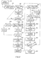
- a method of the present invention analyzes the image for the presence of grids which may have been created by the radiographic grids 60.
- the image processor 90 loads a software program of the present invention which randomly samples 140 two percent of the pixel values stored in memory 100 and 110 for determining the mean value 150 of the sampled pixels 80, which mean value is an estimate of the mean of the entire image. It is instructive to note that two percent sampling is merely the percentage of the preferred embodiment and that any percentage of the pixels 80 may, in fact, be sampled for this estimation. Pixels 80 with a value of the mean or higher are an estimation of where it is easier to detect grids.
- an array of pixels 80 preferably a 16 x 16 array, having a pixel value of the mean or higher is selected 160 for determining the mean value 170 of the 16 x 16 array.
- a 16 x 16 array is preferred, any size array may be used for this sample. If the array mean is below the estimated mean of the image 180, the array is discarded and another 16 x 16 array is sampled 160. If the array mean is at or above the estimated mean of the entire image 180, the array will be further analyzed for the presence of grids.
- the 16 x 16 array is further sampled by sampling two or more lines of pixels which are parallel to an imaginary x-axis or ordinate 190 which is through the center of the array.
- Each pixel 80 from each of the sampled lines which have a same ordinate is then averaged 200 together so that the result is an average pixel value along the ordinate.
- This result is plotted as a graph of pixel value versus pixel location along the ordinate.
- An example of such a plot is shown in Fig. 3. Referring back to the flowchart, this plot is smoothed 210 which is well known in the art and an illustration of which is shown in Fig. 4.
- the smoothed plot is subtracted 220 from the averaged plot for forming a high pass filter of the resultant pixels.
- An example of a plot of the high pass filter is shown in Fig. 5.
- the resultant high pass plot is autocorrelated 230 by techniques which are well known in the art for enhancing the high pass plot (See Detection of Signals in Noise, Whalen 1971 for further disclosure of autocorrelation).
- the autocorrelated 240 plot is again autocorrelated for further still better quality.
- the variance which is a well known statistical technique, is then calculated 230 from the result of this autocorrelation (See Probability and Statistics, DeGroet Addison Wesley 1975 for details of variance calculation).
- Steps 190 through 250 are then repeated for sampling along the y-axis or abscissa, and are recited below for thoroughness of understanding.
- the 16 x 16 array further samples two or lines of pixels which are parallel to an imaginary the abscissa 260 which is also through the center of the array.
- Each pixel from each of the sampled lines which have a same abscissa is then averaged 270 together so that the result is an average pixel value along the abscissa.
- This result is plotted as a graph of pixel value versus pixel location along the abscissa and the plot is smoothed 280.
- the smoothed plot is subtracted 290 from the averaged plot for forming a high pass filter of the resultant pixels.
- the resultant high pass plot is autocorrelated 300 for enhancing the high pass plot.
- the autocorrelated plot is again autocorrelated 310 for further still better quality.
- the variance is then calculated 320 from the result of this autocorrelation.
- a F-test 330 is used for determining whether grids are present in the 16 x 16 sampled array of pixels.
- the average of all the votes 350 are taken and the result indicates whether any grids are present and, if so, what direction they rest.
- the result of the average has the same meaning as the F-test score: positive one means vertical grids, negative one means horizontal grids are present, and a zero indicates no grids are present. If all the pixels have not been included in a 16 x 16 array for analysis 340, the above steps are repeated until they have been included in a 16 x 16 array analysis.
- the average of the pixel value is made according to a predetermined pattern dependent on the location of the 16x16 sampled array with respect to the center of the grid.
- the image processor 90 applies a filter to the image for removing them.
- filters are well known in the art.
Landscapes
- Engineering & Computer Science (AREA)
- Theoretical Computer Science (AREA)
- Computer Vision & Pattern Recognition (AREA)
- Physics & Mathematics (AREA)
- General Physics & Mathematics (AREA)
- Multimedia (AREA)
- Artificial Intelligence (AREA)
- Image Processing (AREA)
- Image Analysis (AREA)
- Transforming Light Signals Into Electric Signals (AREA)
- Apparatus For Radiation Diagnosis (AREA)
- Analysing Materials By The Use Of Radiation (AREA)
- Facsimile Image Signal Circuits (AREA)
Applications Claiming Priority (2)
| Application Number | Priority Date | Filing Date | Title |
|---|---|---|---|
| US379389 | 1995-01-27 | ||
| US08/379,389 US5661818A (en) | 1995-01-27 | 1995-01-27 | Method and system for detecting grids in a digital image |
Publications (3)
| Publication Number | Publication Date |
|---|---|
| EP0723762A2 true EP0723762A2 (de) | 1996-07-31 |
| EP0723762A3 EP0723762A3 (de) | 1997-07-30 |
| EP0723762B1 EP0723762B1 (de) | 2003-03-26 |
Family
ID=23497045
Family Applications (1)
| Application Number | Title | Priority Date | Filing Date |
|---|---|---|---|
| EP19960420011 Expired - Lifetime EP0723762B1 (de) | 1995-01-27 | 1996-01-11 | Verfahren und Vorrichtung zur Detektion von Gittern in einem digitalen Bild |
Country Status (4)
| Country | Link |
|---|---|
| US (1) | US5661818A (de) |
| EP (1) | EP0723762B1 (de) |
| JP (1) | JPH08293020A (de) |
| DE (1) | DE69626876T2 (de) |
Cited By (5)
| Publication number | Priority date | Publication date | Assignee | Title |
|---|---|---|---|---|
| FR2819329A1 (fr) * | 2001-01-11 | 2002-07-12 | Ge Med Sys Global Tech Co Llc | Procede et dispositif de detection automatique d'une pelote de compression graduee d'un appareillage de mammographie |
| EP1696366A1 (de) | 2005-02-24 | 2006-08-30 | Agfa-Gevaert | Verfahren zum Prüfen des Vorhandenseins eines Gittermusters in einem Röntgenbild |
| US7479969B2 (en) | 2005-02-24 | 2009-01-20 | Agfa Healthcare, N.V. | Grid detection method |
| EP2196148A4 (de) * | 2007-10-02 | 2013-06-26 | Shimadzu Corp | Strahlenbild-prozessor und programm zur bearbeitung von strahlenbildern |
| GB2549592A (en) * | 2016-03-17 | 2017-10-25 | Gen Electric | Method and system for reducing grid line artifacts in x-ray image |
Families Citing this family (16)
| Publication number | Priority date | Publication date | Assignee | Title |
|---|---|---|---|---|
| US6173073B1 (en) | 1998-01-05 | 2001-01-09 | Canon Kabushiki Kaisha | System for analyzing table images |
| JP2000083951A (ja) * | 1998-09-11 | 2000-03-28 | Canon Inc | X線画像撮影装置及びグリッド装置 |
| US6850597B2 (en) | 1998-09-11 | 2005-02-01 | Canon Kabushiki Kaisha | X-ray image photographing apparatus and grid device |
| US6269176B1 (en) | 1998-12-21 | 2001-07-31 | Eastman Kodak Company | Method for x-ray antiscatter grid detection and suppression in digital radiography |
| US6711292B2 (en) | 1998-12-30 | 2004-03-23 | Canon Kabushiki Kaisha | Block selection of table features |
| JP2002022957A (ja) * | 2000-07-12 | 2002-01-23 | Nitto Denko Corp | 光学フィルム及びそれを用いた液晶表示装置 |
| JP2003150954A (ja) * | 2001-11-14 | 2003-05-23 | Fuji Photo Film Co Ltd | 周期的パターン抑制処理方法および装置 |
| US7050618B2 (en) * | 2002-02-08 | 2006-05-23 | Eastman Kodak Company | Method for antiscatter stationary grid artifacts detection and attenuation in digital radiographic images |
| US7796792B2 (en) * | 2005-06-29 | 2010-09-14 | Agfa Healthcare, N.V. | Method of identifying disturbing frequencies originating from the presence of an anti-scatter grid during acquisition of a radiation image |
| US7329890B2 (en) * | 2005-07-22 | 2008-02-12 | Carestream Health, Inc. | Computed radiography cassette system |
| US8718348B2 (en) * | 2009-08-07 | 2014-05-06 | Carestream Health, Inc. | Grid suppression in imaging |
| US8433154B2 (en) | 2010-12-13 | 2013-04-30 | Carestream Health, Inc. | Enhanced contrast for scatter compensation in X-ray imaging |
| JP5618880B2 (ja) | 2011-03-24 | 2014-11-05 | 富士フイルム株式会社 | 画像処理装置、画像処理方法並びに画像処理プログラム |
| JP6139897B2 (ja) | 2013-02-05 | 2017-05-31 | キヤノン株式会社 | 画像解析装置、放射線撮影装置、画像解析方法、プログラムおよび記憶媒体 |
| JP5957409B2 (ja) * | 2013-03-29 | 2016-07-27 | 富士フイルム株式会社 | 領域抽出装置および方法並びにプログラム |
| US10058301B2 (en) * | 2014-09-24 | 2018-08-28 | Fujifilm Corporation | Image analysis device, image analysis method, and program |
Family Cites Families (15)
| Publication number | Priority date | Publication date | Assignee | Title |
|---|---|---|---|---|
| NL8202417A (nl) * | 1982-06-15 | 1984-01-02 | Philips Nv | Inrichting en werkwijze voor het verwerken van roentgenbeelden. |
| JPS62191972A (ja) * | 1986-02-18 | 1987-08-22 | Toshiba Corp | X線画像処理装置 |
| NL8603059A (nl) * | 1986-12-01 | 1988-07-01 | Philips Nv | Inrichting en werkwijze met bewegingsartefactreductie voor verschilbeeldbepaling. |
| US4875227A (en) * | 1986-12-06 | 1989-10-17 | Rossi Remo J | Anti-scatter grid system |
| JP2536024B2 (ja) * | 1988-02-29 | 1996-09-18 | 株式会社島津製作所 | X線画像処理装置 |
| US5101448A (en) * | 1988-08-24 | 1992-03-31 | Hitachi, Ltd. | Method and apparatus for processing a document by utilizing an image |
| JPH02202175A (ja) * | 1989-01-30 | 1990-08-10 | Dainippon Screen Mfg Co Ltd | 画像走査記録装置における鮮鋭度強調方法 |
| JPH02237277A (ja) * | 1989-03-09 | 1990-09-19 | Toshiba Corp | X線診断装置 |
| JP2532940B2 (ja) * | 1989-04-06 | 1996-09-11 | 富士写真フイルム株式会社 | 偽画像信号の検出方法 |
| US5202552A (en) * | 1991-04-22 | 1993-04-13 | Macmillan Bloedel Limited | Data with perimeter identification tag |
| JPH0540847A (ja) * | 1991-08-05 | 1993-02-19 | Oki Electric Ind Co Ltd | 表罫線抽出方法 |
| US5294989A (en) * | 1991-09-17 | 1994-03-15 | Moore Color, Inc. | Saturable smoothing grid for image processing |
| US5224177A (en) * | 1991-10-31 | 1993-06-29 | The University Of Chicago | High quality film image correction and duplication method and system |
| FR2696260A1 (fr) * | 1992-09-25 | 1994-04-01 | Thomson Csf | Procédé de délignage d'images optroniques et dispositif pour sa mise en Óoeuvre. |
| US5357554A (en) * | 1993-09-30 | 1994-10-18 | General Electric Company | Apparatus and method for reducing X-ray grid line artifacts |
-
1995
- 1995-01-27 US US08/379,389 patent/US5661818A/en not_active Expired - Fee Related
-
1996
- 1996-01-11 EP EP19960420011 patent/EP0723762B1/de not_active Expired - Lifetime
- 1996-01-11 DE DE69626876T patent/DE69626876T2/de not_active Expired - Lifetime
- 1996-01-25 JP JP1113896A patent/JPH08293020A/ja active Pending
Cited By (8)
| Publication number | Priority date | Publication date | Assignee | Title |
|---|---|---|---|---|
| FR2819329A1 (fr) * | 2001-01-11 | 2002-07-12 | Ge Med Sys Global Tech Co Llc | Procede et dispositif de detection automatique d'une pelote de compression graduee d'un appareillage de mammographie |
| US7050619B2 (en) | 2001-01-11 | 2006-05-23 | Ge Medical Systems Global Technology Company, Llc | Method and device for automatic detection of a graduated compression paddle |
| EP1696366A1 (de) | 2005-02-24 | 2006-08-30 | Agfa-Gevaert | Verfahren zum Prüfen des Vorhandenseins eines Gittermusters in einem Röntgenbild |
| US7479969B2 (en) | 2005-02-24 | 2009-01-20 | Agfa Healthcare, N.V. | Grid detection method |
| EP2196148A4 (de) * | 2007-10-02 | 2013-06-26 | Shimadzu Corp | Strahlenbild-prozessor und programm zur bearbeitung von strahlenbildern |
| GB2549592A (en) * | 2016-03-17 | 2017-10-25 | Gen Electric | Method and system for reducing grid line artifacts in x-ray image |
| US10297010B2 (en) | 2016-03-17 | 2019-05-21 | General Electric Company | Method and system for reducing grid line artifacts in X-ray image |
| GB2549592B (en) * | 2016-03-17 | 2019-10-02 | Gen Electric | Method and system for reducing grid line artifacts in x-ray image |
Also Published As
| Publication number | Publication date |
|---|---|
| EP0723762B1 (de) | 2003-03-26 |
| EP0723762A3 (de) | 1997-07-30 |
| DE69626876T2 (de) | 2003-12-04 |
| JPH08293020A (ja) | 1996-11-05 |
| US5661818A (en) | 1997-08-26 |
| DE69626876D1 (de) | 2003-04-30 |
Similar Documents
| Publication | Publication Date | Title |
|---|---|---|
| EP0723762B1 (de) | Verfahren und Vorrichtung zur Detektion von Gittern in einem digitalen Bild | |
| US7689055B2 (en) | Method and apparatus for enhancing image acquired by radiographic system | |
| US7046307B1 (en) | Video signal noise level estimator | |
| US9922409B2 (en) | Edge emphasis in processing images based on radiation images | |
| JP6139897B2 (ja) | 画像解析装置、放射線撮影装置、画像解析方法、プログラムおよび記憶媒体 | |
| JPH11112877A (ja) | 骨計測方法および装置 | |
| EP1014856B1 (de) | Röntgenstrahl-bildverarbeitung | |
| US8634630B2 (en) | Method and apparatus for enhancing representations of micro-calcifications in a digital mammogram image | |
| US6204891B1 (en) | Method for the temporal filtering of the noise in an image of a sequence of digital images, and device for carrying out this method | |
| JP4393483B2 (ja) | 放射線画像処理装置、画像処理システム、放射線画像処理方法、記憶媒体及びプログラム | |
| US7508994B2 (en) | Method for detecting streaks in digital images | |
| JP3148187B2 (ja) | パーティクルモニタシステム及びパーティクル検出方法並びにパーティクル検出プログラムを格納した記録媒体 | |
| JP2014176565A (ja) | 画像処理装置、放射線撮影装置、画像処理方法、コンピュータプログラム及び記憶媒体 | |
| JP2019202019A (ja) | 体厚推定装置、放射線画像処理装置、体厚の推定方法及びプログラム | |
| JPH09248293A (ja) | 骨粗しょう症診断装置 | |
| JP2720383B2 (ja) | 画像内濃淡領域検出装置 | |
| JPS61133847A (ja) | X線画像における散乱線除去画像製造法 | |
| JP3793039B2 (ja) | 画像処理方法、画像処理装置、放射線画像処理装置、画像処理システム及びプログラム | |
| JP3825989B2 (ja) | 放射線画像処理装置、画像処理システム、放射線画像処理方法、コンピュータ読出可能な記憶媒体、及びコンピュータプログラム | |
| JPH0898830A (ja) | X線ct装置における有効視野はみ出し検出装置、x線ct装置におけるリファレンス補正装置、x線ct装置 | |
| JPH0740293B2 (ja) | X線画像処理装置 | |
| US11983855B2 (en) | Image processing apparatus, image processing method, and program | |
| EP0654762A1 (de) | Darstellung von diagnostisch irrelevanten Gebieten in radiographischen Bildern | |
| JPH0666855B2 (ja) | 照射野検出装置 | |
| JP4393436B2 (ja) | 放射線画像処理装置、画像処理システム、放射線画像処理方法、記憶媒体及びプログラム |
Legal Events
| Date | Code | Title | Description |
|---|---|---|---|
| PUAI | Public reference made under article 153(3) epc to a published international application that has entered the european phase |
Free format text: ORIGINAL CODE: 0009012 |
|
| AK | Designated contracting states |
Kind code of ref document: A2 Designated state(s): DE FR GB |
|
| PUAL | Search report despatched |
Free format text: ORIGINAL CODE: 0009013 |
|
| AK | Designated contracting states |
Kind code of ref document: A3 Designated state(s): DE FR GB |
|
| 17P | Request for examination filed |
Effective date: 19971204 |
|
| 17Q | First examination report despatched |
Effective date: 20011213 |
|
| GRAG | Despatch of communication of intention to grant |
Free format text: ORIGINAL CODE: EPIDOS AGRA |
|
| RIC1 | Information provided on ipc code assigned before grant |
Free format text: 7G 06T 5/00 A |
|
| GRAG | Despatch of communication of intention to grant |
Free format text: ORIGINAL CODE: EPIDOS AGRA |
|
| GRAH | Despatch of communication of intention to grant a patent |
Free format text: ORIGINAL CODE: EPIDOS IGRA |
|
| GRAH | Despatch of communication of intention to grant a patent |
Free format text: ORIGINAL CODE: EPIDOS IGRA |
|
| GRAA | (expected) grant |
Free format text: ORIGINAL CODE: 0009210 |
|
| AK | Designated contracting states |
Designated state(s): DE FR GB |
|
| REG | Reference to a national code |
Ref country code: GB Ref legal event code: FG4D |
|
| REF | Corresponds to: |
Ref document number: 69626876 Country of ref document: DE Date of ref document: 20030430 Kind code of ref document: P |
|
| ET | Fr: translation filed | ||
| PLBE | No opposition filed within time limit |
Free format text: ORIGINAL CODE: 0009261 |
|
| STAA | Information on the status of an ep patent application or granted ep patent |
Free format text: STATUS: NO OPPOSITION FILED WITHIN TIME LIMIT |
|
| 26N | No opposition filed |
Effective date: 20031230 |
|
| PGFP | Annual fee paid to national office [announced via postgrant information from national office to epo] |
Ref country code: GB Payment date: 20041210 Year of fee payment: 10 |
|
| PGFP | Annual fee paid to national office [announced via postgrant information from national office to epo] |
Ref country code: FR Payment date: 20050105 Year of fee payment: 10 |
|
| PGFP | Annual fee paid to national office [announced via postgrant information from national office to epo] |
Ref country code: DE Payment date: 20050131 Year of fee payment: 10 |
|
| PG25 | Lapsed in a contracting state [announced via postgrant information from national office to epo] |
Ref country code: GB Free format text: LAPSE BECAUSE OF NON-PAYMENT OF DUE FEES Effective date: 20060111 |
|
| PG25 | Lapsed in a contracting state [announced via postgrant information from national office to epo] |
Ref country code: FR Free format text: LAPSE BECAUSE OF NON-PAYMENT OF DUE FEES Effective date: 20060131 |
|
| PG25 | Lapsed in a contracting state [announced via postgrant information from national office to epo] |
Ref country code: DE Free format text: LAPSE BECAUSE OF THE APPLICANT RENOUNCES Effective date: 20060221 |
|
| GBPC | Gb: european patent ceased through non-payment of renewal fee |
Effective date: 20060111 |
|
| REG | Reference to a national code |
Ref country code: FR Ref legal event code: ST Effective date: 20060929 |