EP0724340A1 - Appareil de communication optique en espace libre - Google Patents
Appareil de communication optique en espace libre Download PDFInfo
- Publication number
- EP0724340A1 EP0724340A1 EP96100980A EP96100980A EP0724340A1 EP 0724340 A1 EP0724340 A1 EP 0724340A1 EP 96100980 A EP96100980 A EP 96100980A EP 96100980 A EP96100980 A EP 96100980A EP 0724340 A1 EP0724340 A1 EP 0724340A1
- Authority
- EP
- European Patent Office
- Prior art keywords
- signal
- frequency
- detecting
- light signal
- variable
- Prior art date
- Legal status (The legal status is an assumption and is not a legal conclusion. Google has not performed a legal analysis and makes no representation as to the accuracy of the status listed.)
- Granted
Links
- 230000003287 optical effect Effects 0.000 title claims abstract description 60
- 230000005540 biological transmission Effects 0.000 claims abstract description 34
- 230000001902 propagating effect Effects 0.000 claims abstract description 7
- 238000001514 detection method Methods 0.000 claims description 16
- 230000007423 decrease Effects 0.000 claims description 6
- 238000000034 method Methods 0.000 claims description 4
- 238000006243 chemical reaction Methods 0.000 description 4
- 230000003247 decreasing effect Effects 0.000 description 2
- 238000009434 installation Methods 0.000 description 2
- 230000015556 catabolic process Effects 0.000 description 1
- 238000006731 degradation reaction Methods 0.000 description 1
Images


Classifications
-
- H—ELECTRICITY
- H04—ELECTRIC COMMUNICATION TECHNIQUE
- H04B—TRANSMISSION
- H04B10/00—Transmission systems employing electromagnetic waves other than radio-waves, e.g. infrared, visible or ultraviolet light, or employing corpuscular radiation, e.g. quantum communication
- H04B10/11—Arrangements specific to free-space transmission, i.e. transmission through air or vacuum
- H04B10/112—Line-of-sight transmission over an extended range
- H04B10/1121—One-way transmission
Definitions
- the present invention relates to an optical space communication apparatus provided with a function to correct an angle of transmitting light or receiving light, which performs two-way information transmission by propagating a light signal in a beam shape in a free space.
- a transmission-side device transmits a signal in which a pilot signal is superimposed on a main signal (transmission signal), and a reception-side device detects the pilot signal to extract information about an angle deviation between the optical axis of a receiving optical system and the receiving light, thereby adjusting the angle upon start of transmission or correcting the angle during transmission.
- a generally employed method for detecting the angular deviation is one arranged in such a manner that a receiving light spot focused by the receiving optical system is guided onto a photodetector and the photodetector detects a position of the spot.
- the pilot signal is a signal having a frequency band different from and narrower than that of the main signal.
- An example of the pilot signal is a sinusoidal signal.
- the photosensor employed is a PSD (Position Sensitive Detector) or a CCD (Charge Coupled Device), which demonstrates weakness with respect to the response speed when the frequency of the pilot signal is high.
- a method for overcoming it employs an array of plural photodiodes with fast response speed and detects differences of outputs from the photodiodes. For example, as shown in Fig. 1, photodetectors 1a to 1d with same characteristics are located in the four quadrants, respectively, and light intensities thereof are obtained through load impedances 2a to 2d and low limiting circuits 3a to 3d, finally obtaining a position of the receiving light spot from sums and differences of these outputs.
- the reason why the pilot signal is used is that high-sensitive reception is possible because of its narrower band than that of the main signal and that the control function can be maintained even if the main signal becomes weak or even if there is no input of the main signal. Further, influence of background light can be decreased when the angular deviation is detected with the pilot signal having a certain high frequency component, different from low frequency components such as dc light.
- the system of the above type includes the low limiting circuits 3a to 3d in order to avoid degradation of the accuracy of angular deviation information.
- the background light is all light other than the light transmitted from the transmission-side device, in the light entering the reception-side device.
- the background light includes the sun light, lights of buildings, etc.
- shot noise increases in the photodiodes used as photodetectors when the background light greatly increases, for example when the direct rays of the sun are incident on the photodiodes. In that case, the shot noise is detected as multiplexed with the pilot signal. This causes a problem of erroneous angle correction when only the shot noise due to the background light exceeds the low limiting value in spite of absence of incidence of the pilot light.
- An object of the present invention is to provide an optical space communication apparatus which can correct the angle of transmitting light or receiving light without any practical trouble even with an extreme increase of the background light, solving the above problem.
- the present invention provides an optical space communication apparatus for performing communication by propagating a light signal in a free space, comprising: multiplexing means for multiplexing a first pilot signal with a transmission signal; first converting means for converting a first electric signal from the multiplexing means into a first light signal; a transmitting optical system for transmitting the first light signal to a party apparatus; a receiving optical system for receiving a second light signal including a second pilot signal, having been transmitted from the party apparatus; second converting means for converting said second light signal into a second electric signal; a first band-pass filter having a pass region comprising a frequency of the second pilot signal; first detecting means for detecting the second electric signal having passed through the first band-pass filter; a second band-pass filter having a pass region not including the frequency of the second pilot signal; second detecting means for detecting the second electric signal having passed through the second band-pass filter; adjusting means for adjusting an angle of the receiving optical system; control means for controlling the adjusting means; and
- the present invention further provides an optical space communication apparatus, which is provided with a function to adjust an angle of a receiving optical system so as to keep the optical axis of the transmission optical system aligned with the optical axis of the receiving optical system and which performs two-way information transmission with light signals between apparatus opposed to each other at a predetermined distance
- the optical space communication apparatus comprising generating means for generating a first pilot signal in a sinusoidal form, multiplexing means for multiplexing the first pilot signal with a transmission signal, electro-optical converting means for converting a first electric signal from the multiplexing means into a first light signal, a transmitting optical system having beam size variable means for making the beam size variable on the reception side (on the party side) of the first light signal, a receiving optical system for receiving a second light signal comprising a second pilot signal, having been transmitted from the party apparatus opposed in order to detect an angular deviation of the receiving optical system, a plurality of segmental opto-electrical conversion elements each for receiving the second
- the optical space communication apparatus having the above configuration is arranged to multiplex the pilot signal with the main signal being the transmission signal, to convert the first electric signal thus made into the first light signal, and to transmit the light signal as adjusting the beam size to a predetermined size on the reception side.
- the second light signal comprising the pilot signal from the party apparatus is received by the plurality of segmental opto-electrical conversion elements to be converted into second electric signals, these electric signals are split each into two signals, the signals are let to pass the band-pass filters having the pass region comprising the frequency of the pilot signal of the party apparatus and the band-pass filters having the pass region not including the frequency of the pilot signal of the party apparatus, and the detection means detects the respective signals.
- Angle correction of the transmitting optical system is effected by changing the cut-off frequency of the servo system loop filter, based on these detection signals, and then two-way information transmission is performed between the transmission apparatus opposed to each other as being apart at a predetermined distance.
- optical space communication apparatus of the present invention will be explained in detail by reference to the embodiment depicted in Fig. 2 to Fig. 5.
- Fig. 2 is a structural drawing to show the two-way optical space communication apparatus, in which in a light transmission unit 10 an output of a generator 12 for generating the sinusoidal pilot signal as described previously is connected to a wavelength multiplexer 11 for receiving a transmission signal and an output (first electric signal) of the multiplexer 11 is connected to an electro-optical converter 13. There are a lens system 14, a polarizing beam splitter 15, and an optical-axis angle adjustment drive mechanism 16 arranged on the optical path ahead of the electro-optical converter 13.
- a beam splitter 17 is located on the optical path in the direction of reflection of the polarizing beam splitter 15.
- a main signal detector 18 for detecting the main signal and outputting a reception signal is placed in the direction of transmission of the beam splitter 17, and an angle deviation detector 19 is placed in the direction of reflection of the beam splitter 17, thereby composing a light reception unit 20.
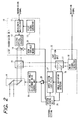
- the angular deviation detector 19 is divided into four photodetection elements 19a to 19d, as shown in Fig. 3, and electric signals from the respective elements are supplied to the load impedances 21a to 21d. Further, each of these electric signals is split into two, which are supplied through band-pass filter 22a to 22d and band-pass filter 23a to 23d to corresponding detectors 24a to 24d and 25a to 25d.
- An output of the angle deviation detector 19 is connected to a system control unit 26 having an external condition setting device and to a servo system loop filter 27, and an output of the system control unit 26 is connected to the servo system loop filter 27, to an amplifier 28, and to a beam size variable means 29 for driving the lens system 14. Further, an output of the amplifier 28 is connected through an optical-axis angle adjustment drive control unit 30 to the optical-axis angle adjustment drive mechanism 16. Further, an output of the servo system loop filter 27 is connected to the amplifier 28.
- the main signal being the transmission signal
- the main signal is multiplexed in the multiplexer 11 with the first pilot signal from the pilot signal generator 12, the thus multiplexed signal is converted into a first light signal (first light beam) in the electro-optical converter 13, the beam size variable means 29 for changing the beam size of the transmission beam moves the lens system 14 along the optical axis to control the beam size so that a predetermined beam size may be achieved at a position where a party apparatus is located, and the light signal is transmitted through the polarizing beam splitter 15 and optical-axis angle adjustment drive mechanism 16.
- a second light signal (second light beam) sent from the party apparatus and including a second pilot signal is guided through the optical-axis angle adjustment drive mechanism 16 and polarizing beam splitter 15 to the light reception unit 20, where it is split by the beam splitter 17 into two beams traveling toward the main signal detector 18 and toward the angle deviation detector 19.
- the main signal detector 18 receives the main signal to output the reception signal
- the angle deviation detector 19 receives the second pilot signal sent from the party apparatus by each of the four segmental detection elements 19a to 19d, which generate electric currents corresponding to light intensities of received light. These current signals are converted into voltage signals (second electric signals) in the load impedances 21a to 21d.
- Each of these voltage signals is split into two signals, the bands of which are limited by the band-pass filter 22a to 22d and band-pass filter 23a to 23d. After that, the voltage signals are detected by the associated detectors 24a to 24d and 25a to 25d to become detection signals Va to Vd and Va' to Vd' corresponding to respective receiving-light levels.
- the detection signals Va to Vd are used to detect the angular deviation between the receiving light and the optical axis of the light reception unit 20.
- the system control unit 26 controls the servo system loop filter 27, amplifier 28, and beam variable means 29 to send a signal to the optical-axis angle adjustment drive control unit 30, whereby the optical-axis angle adjustment drive control unit 30 controls the optical-axis angle adjustment drive mechanism 16 to correct the angular deviation.
- the optical axis of the light transmission unit 10 is preliminarily aligned with the optical axis of the light reception unit 20.
- the transmission light can be sent on the same optical axis as the receiving light is transmitted from the party apparatus.
- Two-way optical space communication as being always stable becomes possible by the above operation between the apparatus opposed to each other.
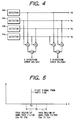
- Fig. 5 shows the band-pass filters 22a to 22d, 23a to 23d, in which, letting f0 be the frequency of the second pilot signal transmitted from the party apparatus, the band-pass filters 22a to 22d include the frequency f0 in the pass region and the band-pass filters 23a to 23d do not include the frequency f0 in the pass region.
- the pass regions of the band-pass filters 22a to 22d and band-pass filters 23a to 23d do not have to be continuously arranged. They may be set apart from each other or may overlap with each other. Further, one pass region may be included completely in the other. The point is whether the pass region includes the frequency f0 or not.
- the shot noise due to the background light can be considered to have almost uniform noise power per unit frequency within a certain frequency range.
- the S/N ratio of the detection signal Va including the frequency f0 can be calculated based on the detection signals Va and Va'. This is because the detection signal Va is a signal in which the shot noise is multiplexed with the second pilot signal and the detection signal Va' is a signal which represents only the shot noise.
- the same means can also be used to recognize the noise light when only the noise light is incident without incidence of the second pilot signal. When absence of incidence of the second pilot signal is recognized from the detection signals Va to Vd and Va' to Vd' and even if the values of the detection signals Va to Vd are not less than the low limiting value set, the all values are set to the lower limiting value.
- the system control unit 26 determines from the detection signals Va to Vd and Va' to Vd' that the level of the background light is too high to accurately perform the angle correction of the receiving light because the strong background light could degrade the S/N ratio of the second pilot signal used in detecting the angular deviation, the system control unit 26 lowers the cut-off frequency of the servo system loop filter 27 for angle correction, thereby performing the angle correction of the receiving light without practical trouble by controlling the optical-axis angle adjustment drive mechanism 16. Namely, when it is considered that there is no extremely quick vibration because of good installation conditions of apparatus, the S/N ratio of the second pilot signal used in detecting the angular deviation can be improved by lowering the frequency characteristics of the servo system loop filter 27.
- the system control unit 26 determines from the detection signals Va to Vd and Va' to Vd' that accurate angle correction of the receiving light cannot be done and if the installation conditions do not allow the frequency characteristics of the servo system loop filter 27 to be lowered, the system control unit 26 decreases the servo system loop gain as victimizing the accuracy of angle correction and further controls the beam variable means 29 to enlarge the size of the transmission beam to the party apparatus opposed in order to compensate for the decrease of the loop gain. This results in decreasing a margin for attenuation of light signal on the transmission path.
- the cut-off frequency and the loop gain of the servo system loop filter 27 for controlling the angle of the receiving optical system can be arranged as to be variable in such a manner that the detection signals Va to Vd are subjected to analog-digital conversion, the digital signals are taken into a CPU in the control unit 26, and they are made variable on software or by using an analog circuit. Further, the size of the transmission beam to the party apparatus opposed can be made variable by horizontally moving the lens system 14 disposed between the electro-optical converter 13 and the polarizing beam splitter 15 along the optical axis, and the control of movement of the lens system is executed by the CPU in the control unit 26.
- the optical space communication apparatus is arranged in such a manner that the angular deviation detecting unit of receiving light can independently detect the receiving level of the pilot signal and the receiving level of shot noise due to the background light, whereby the apparatus can perform the angle correction of receiving light without practical trouble even with an extreme increase of the shot noise due to the background light.
Landscapes
- Physics & Mathematics (AREA)
- Electromagnetism (AREA)
- Engineering & Computer Science (AREA)
- Computer Networks & Wireless Communication (AREA)
- Signal Processing (AREA)
- Optical Communication System (AREA)
Applications Claiming Priority (2)
| Application Number | Priority Date | Filing Date | Title |
|---|---|---|---|
| JP28922/95 | 1995-01-26 | ||
| JP02892295A JP3311187B2 (ja) | 1995-01-26 | 1995-01-26 | 双方向光空間伝送装置 |
Publications (2)
| Publication Number | Publication Date |
|---|---|
| EP0724340A1 true EP0724340A1 (fr) | 1996-07-31 |
| EP0724340B1 EP0724340B1 (fr) | 1999-04-21 |
Family
ID=12261904
Family Applications (1)
| Application Number | Title | Priority Date | Filing Date |
|---|---|---|---|
| EP96100980A Expired - Lifetime EP0724340B1 (fr) | 1995-01-26 | 1996-01-24 | Appareil de communication optique en espace libre et procédé d'ajustage d'angles |
Country Status (4)
| Country | Link |
|---|---|
| US (1) | US5684614A (fr) |
| EP (1) | EP0724340B1 (fr) |
| JP (1) | JP3311187B2 (fr) |
| DE (1) | DE69602110T2 (fr) |
Cited By (9)
| Publication number | Priority date | Publication date | Assignee | Title |
|---|---|---|---|---|
| EP0866572A3 (fr) * | 1997-03-19 | 1999-12-01 | AT&T Corp. | Emetteur-récepteur optique à chemin optique commun pour l'émission et la réception |
| EP0876014A3 (fr) * | 1997-05-01 | 1999-12-29 | AT&T Corp. | Commande automatique de gain pour liaisons optiques de transmission dans l'espace libre |
| EP1195926A1 (fr) * | 2000-10-05 | 2002-04-10 | Lucent Technologies Inc. | Procédé et Dispositif pour contrôler les niveaux de puissance reçus dans un système de communication optique en espace libre |
| EP0911996A3 (fr) * | 1997-10-24 | 2003-07-30 | Canon Kabushiki Kaisha | Dispositif pour communication optique dans l'espace |
| EP0880242A3 (fr) * | 1997-05-20 | 2003-09-24 | Canon Kabushiki Kaisha | Dispositif de transmission optique spatiale bidirectionelle |
| WO2005101704A1 (fr) | 2004-04-13 | 2005-10-27 | Koninklijke Philips Electronics N.V. | Perfectionnements apportes a la reception dans des reseaux optiques |
| EP1130807A3 (fr) * | 2000-01-20 | 2005-12-21 | NEC TOSHIBA Space Systems, Ltd. | Equipement de communication pour signal optique en espace libre |
| CN106125081A (zh) * | 2015-05-07 | 2016-11-16 | 通用汽车环球科技运作有限责任公司 | 带有光通讯的激光雷达 |
| WO2017200726A1 (fr) * | 2016-05-17 | 2017-11-23 | Google Llc | Appareil d'acquisition et de suivi pour communications optiques en espace libre |
Families Citing this family (20)
| Publication number | Priority date | Publication date | Assignee | Title |
|---|---|---|---|---|
| JP3323651B2 (ja) * | 1993-09-24 | 2002-09-09 | キヤノン株式会社 | 光空間通信装置 |
| JP3311197B2 (ja) * | 1995-03-22 | 2002-08-05 | キヤノン株式会社 | 双方向光空間伝送装置 |
| US6256129B1 (en) * | 1997-03-28 | 2001-07-03 | Samsung Electronics Co., Ltd. | Portable computer and method of automatically controlling direction of infrared signal transmission and reception |
| US6016212A (en) * | 1997-04-30 | 2000-01-18 | At&T Corp | Optical receiver and demultiplexer for free-space wavelength division multiplexing communications systems |
| JPH11136190A (ja) * | 1997-10-24 | 1999-05-21 | Canon Inc | 光空間通信装置 |
| JP2001326608A (ja) * | 2000-05-15 | 2001-11-22 | Canon Inc | 光空間通信装置 |
| US6483621B1 (en) * | 2000-07-28 | 2002-11-19 | Terabeam Corporation | Method and apparatus for tone tracking in wireless optical communication systems |
| US7236709B1 (en) * | 2000-10-20 | 2007-06-26 | Avanex Corporation | Multi-input wavelocker for controlling laser wavelengths of multiple lasers |
| US6510401B2 (en) | 2001-05-11 | 2003-01-21 | The United States Of America As Represented By The Director Of The National Security Agency | Method of authenticating beacon |
| US6970651B1 (en) * | 2001-07-31 | 2005-11-29 | Terabeam Corporation | High-sensitivity tracking in free-space optical communication systems |
| US6987932B2 (en) * | 2001-11-05 | 2006-01-17 | International Business Machines Corporation | Apparatus and method for controlling an optical transceiver |
| US7389052B2 (en) * | 2002-01-30 | 2008-06-17 | Texas Instruments Incorporated | Calibration method for station orientation |
| US7391975B2 (en) * | 2002-04-29 | 2008-06-24 | Texas Instruments Incorporated | Method of synchronizing servo timing in an optical wireless link |
| ITMI20021938A1 (it) * | 2002-09-12 | 2004-03-13 | Cit Alcatel | Ricevitore per sistema di trasmissione ottico in aria in grado di valutare le cause di un'eventuale diminuzione di potenza ricevuta |
| US20040258415A1 (en) * | 2003-06-18 | 2004-12-23 | Boone Bradley G. | Techniques for secure free space laser communications |
| US8200094B1 (en) * | 2009-04-11 | 2012-06-12 | Applied Micro Circuits Corporation | System and method for free space optical connector alignment |
| JP5991697B2 (ja) * | 2013-12-19 | 2016-09-14 | インターナショナル・ビジネス・マシーンズ・コーポレーションInternational Business Machines Corporation | 光接続装置、情報処理装置及びデータ伝送方法 |
| US9413448B2 (en) * | 2014-08-08 | 2016-08-09 | Nxgen Partners Ip, Llc | Systems and methods for focusing beams with mode division multiplexing |
| EP4099583B1 (fr) * | 2020-01-27 | 2025-10-22 | Shimadzu Corporation | Structure de branche de fibre pour communication optique spatiale et système de communication optique doté de cette dernière |
| US11307367B2 (en) * | 2020-08-17 | 2022-04-19 | X Development Llc | Method of precision beam collimation using fiber-optic circulator and wavelength tunable source |
Citations (4)
| Publication number | Priority date | Publication date | Assignee | Title |
|---|---|---|---|---|
| JPH02236477A (ja) * | 1989-03-10 | 1990-09-19 | Mitsubishi Electric Corp | 光ビーム追尾装置 |
| EP0560315A2 (fr) * | 1992-03-11 | 1993-09-15 | GRUNDIG E.M.V. Elektro-Mechanische Versuchsanstalt Max Grundig GmbH & Co. KG | Dispositif pour la transmission de signaux optiques dans l'espace libre |
| JPH06152516A (ja) * | 1992-11-10 | 1994-05-31 | Canon Inc | 光空間伝送装置 |
| EP0653852A1 (fr) * | 1993-11-16 | 1995-05-17 | Canon Kabushiki Kaisha | Système de communication optique dans l'espace libre |
Family Cites Families (6)
| Publication number | Priority date | Publication date | Assignee | Title |
|---|---|---|---|---|
| US3566128A (en) * | 1968-06-17 | 1971-02-23 | Bell Telephone Labor Inc | Optical communication arrangement utilizing a multimode optical regenerative amplifier for pilot frequency amplification |
| DE3855021T2 (de) * | 1987-04-13 | 1996-07-18 | Nippon Electric Co | Optisches Ausrichtungssystem |
| JP2705104B2 (ja) * | 1988-05-20 | 1998-01-26 | ソニー株式会社 | 送信装置 |
| US5142400A (en) * | 1989-12-26 | 1992-08-25 | Cubic Corporation | Method and apparatus for automatic acquisition and alignment of an optical beam communication link |
| JP3187495B2 (ja) * | 1991-12-28 | 2001-07-11 | ソニー株式会社 | 光空間伝送装置 |
| JP3132690B2 (ja) * | 1992-06-30 | 2001-02-05 | ソニー株式会社 | 光空間伝送装置 |
-
1995
- 1995-01-26 JP JP02892295A patent/JP3311187B2/ja not_active Expired - Fee Related
-
1996
- 1996-01-24 EP EP96100980A patent/EP0724340B1/fr not_active Expired - Lifetime
- 1996-01-24 DE DE69602110T patent/DE69602110T2/de not_active Expired - Fee Related
- 1996-01-25 US US08/591,722 patent/US5684614A/en not_active Expired - Fee Related
Patent Citations (4)
| Publication number | Priority date | Publication date | Assignee | Title |
|---|---|---|---|---|
| JPH02236477A (ja) * | 1989-03-10 | 1990-09-19 | Mitsubishi Electric Corp | 光ビーム追尾装置 |
| EP0560315A2 (fr) * | 1992-03-11 | 1993-09-15 | GRUNDIG E.M.V. Elektro-Mechanische Versuchsanstalt Max Grundig GmbH & Co. KG | Dispositif pour la transmission de signaux optiques dans l'espace libre |
| JPH06152516A (ja) * | 1992-11-10 | 1994-05-31 | Canon Inc | 光空間伝送装置 |
| EP0653852A1 (fr) * | 1993-11-16 | 1995-05-17 | Canon Kabushiki Kaisha | Système de communication optique dans l'espace libre |
Non-Patent Citations (2)
| Title |
|---|
| PATENT ABSTRACTS OF JAPAN vol. 14, no. 554 (P - 1140) 1990 * |
| PATENT ABSTRACTS OF JAPAN vol. 18, no. 467 (E - 1599) 1994 * |
Cited By (13)
| Publication number | Priority date | Publication date | Assignee | Title |
|---|---|---|---|---|
| EP0866572A3 (fr) * | 1997-03-19 | 1999-12-01 | AT&T Corp. | Emetteur-récepteur optique à chemin optique commun pour l'émission et la réception |
| US6154297A (en) * | 1997-03-19 | 2000-11-28 | At&T Corp | Optical transceiver using common optical path for transmission and reception |
| EP0876014A3 (fr) * | 1997-05-01 | 1999-12-29 | AT&T Corp. | Commande automatique de gain pour liaisons optiques de transmission dans l'espace libre |
| EP0880242A3 (fr) * | 1997-05-20 | 2003-09-24 | Canon Kabushiki Kaisha | Dispositif de transmission optique spatiale bidirectionelle |
| EP0911996A3 (fr) * | 1997-10-24 | 2003-07-30 | Canon Kabushiki Kaisha | Dispositif pour communication optique dans l'espace |
| EP1130807A3 (fr) * | 2000-01-20 | 2005-12-21 | NEC TOSHIBA Space Systems, Ltd. | Equipement de communication pour signal optique en espace libre |
| US6643467B1 (en) | 2000-10-05 | 2003-11-04 | Lucent Technologies Inc. | Method and apparatus for controlling received power levels within a free space optical communication system |
| EP1195926A1 (fr) * | 2000-10-05 | 2002-04-10 | Lucent Technologies Inc. | Procédé et Dispositif pour contrôler les niveaux de puissance reçus dans un système de communication optique en espace libre |
| WO2005101704A1 (fr) | 2004-04-13 | 2005-10-27 | Koninklijke Philips Electronics N.V. | Perfectionnements apportes a la reception dans des reseaux optiques |
| CN106125081A (zh) * | 2015-05-07 | 2016-11-16 | 通用汽车环球科技运作有限责任公司 | 带有光通讯的激光雷达 |
| WO2017200726A1 (fr) * | 2016-05-17 | 2017-11-23 | Google Llc | Appareil d'acquisition et de suivi pour communications optiques en espace libre |
| US10039103B2 (en) | 2016-05-17 | 2018-07-31 | X Development Llc | Acquisition and tracking apparatus for free space optical communications |
| US10420108B2 (en) | 2016-05-17 | 2019-09-17 | X Development Llc | Acquisition and tracking apparatus for free space optical communications |
Also Published As
| Publication number | Publication date |
|---|---|
| JP3311187B2 (ja) | 2002-08-05 |
| US5684614A (en) | 1997-11-04 |
| DE69602110T2 (de) | 1999-12-23 |
| EP0724340B1 (fr) | 1999-04-21 |
| DE69602110D1 (de) | 1999-05-27 |
| JPH08204645A (ja) | 1996-08-09 |
Similar Documents
| Publication | Publication Date | Title |
|---|---|---|
| US5684614A (en) | Optical space communication apparatus | |
| US5594580A (en) | Optical space communication apparatus | |
| US6122084A (en) | High dynamic range free-space optical communication receiver | |
| US6178024B1 (en) | Optical space communication apparatus | |
| US5610748A (en) | Optical space communication apparatus sending main signals and an auxiliary signal for controlling the intensity at the receiver | |
| US20050265724A1 (en) | Optical-transmission-space determining apparatus and optical-space transmission apparatus | |
| EP0911996B1 (fr) | Dispositif pour communication optique dans l'espace | |
| AU746734B2 (en) | Offset control for burst-mode optical receiver | |
| US20010009466A1 (en) | Spatial light communication equipment | |
| JPS61105245A (ja) | 車両用ヘツドライト自動切替装置 | |
| JP3206993B2 (ja) | 双方向光空間伝送装置 | |
| EP1416651B1 (fr) | Récepteur optique | |
| JPH08223117A (ja) | 光空間伝送装置 | |
| EP0880242A2 (fr) | Dispositif de transmission optique spatiale bidirectionelle | |
| JPH08149076A (ja) | 光空間通信装置 | |
| JPH0236622A (ja) | 光ヘテロダイン受信装置 | |
| JP3093237B2 (ja) | 光通信用端末装置 | |
| CN223729747U (zh) | 网络节点以及光网络 | |
| JP3368103B2 (ja) | 双方向光空間伝送装置 | |
| JP2851066B2 (ja) | 妨害光遮断装置 | |
| JP2009010444A (ja) | 光空間通信装置 | |
| JPH0715644B2 (ja) | 光ビ−ム追尾機構 | |
| JPH04119022A (ja) | 光空間通信用の受信装置 | |
| JPH04158639A (ja) | 光受信回路 | |
| JPH01241930A (ja) | 光空間伝送装置 |
Legal Events
| Date | Code | Title | Description |
|---|---|---|---|
| PUAI | Public reference made under article 153(3) epc to a published international application that has entered the european phase |
Free format text: ORIGINAL CODE: 0009012 |
|
| AK | Designated contracting states |
Kind code of ref document: A1 Designated state(s): DE FR GB NL |
|
| 17P | Request for examination filed |
Effective date: 19970130 |
|
| 17Q | First examination report despatched |
Effective date: 19970307 |
|
| GRAG | Despatch of communication of intention to grant |
Free format text: ORIGINAL CODE: EPIDOS AGRA |
|
| GRAG | Despatch of communication of intention to grant |
Free format text: ORIGINAL CODE: EPIDOS AGRA |
|
| GRAH | Despatch of communication of intention to grant a patent |
Free format text: ORIGINAL CODE: EPIDOS IGRA |
|
| GRAH | Despatch of communication of intention to grant a patent |
Free format text: ORIGINAL CODE: EPIDOS IGRA |
|
| GRAA | (expected) grant |
Free format text: ORIGINAL CODE: 0009210 |
|
| AK | Designated contracting states |
Kind code of ref document: B1 Designated state(s): DE FR GB NL |
|
| PG25 | Lapsed in a contracting state [announced via postgrant information from national office to epo] |
Ref country code: NL Free format text: LAPSE BECAUSE OF FAILURE TO SUBMIT A TRANSLATION OF THE DESCRIPTION OR TO PAY THE FEE WITHIN THE PRESCRIBED TIME-LIMIT Effective date: 19990421 |
|
| REF | Corresponds to: |
Ref document number: 69602110 Country of ref document: DE Date of ref document: 19990527 |
|
| ET | Fr: translation filed | ||
| PLBE | No opposition filed within time limit |
Free format text: ORIGINAL CODE: 0009261 |
|
| STAA | Information on the status of an ep patent application or granted ep patent |
Free format text: STATUS: NO OPPOSITION FILED WITHIN TIME LIMIT |
|
| 26N | No opposition filed | ||
| REG | Reference to a national code |
Ref country code: GB Ref legal event code: IF02 |
|
| PGFP | Annual fee paid to national office [announced via postgrant information from national office to epo] |
Ref country code: DE Payment date: 20090131 Year of fee payment: 14 |
|
| PGFP | Annual fee paid to national office [announced via postgrant information from national office to epo] |
Ref country code: GB Payment date: 20090127 Year of fee payment: 14 |
|
| PGFP | Annual fee paid to national office [announced via postgrant information from national office to epo] |
Ref country code: FR Payment date: 20090121 Year of fee payment: 14 |
|
| GBPC | Gb: european patent ceased through non-payment of renewal fee |
Effective date: 20100124 |
|
| REG | Reference to a national code |
Ref country code: FR Ref legal event code: ST Effective date: 20100930 |
|
| PG25 | Lapsed in a contracting state [announced via postgrant information from national office to epo] |
Ref country code: FR Free format text: LAPSE BECAUSE OF NON-PAYMENT OF DUE FEES Effective date: 20100201 |
|
| PG25 | Lapsed in a contracting state [announced via postgrant information from national office to epo] |
Ref country code: DE Free format text: LAPSE BECAUSE OF NON-PAYMENT OF DUE FEES Effective date: 20100803 |
|
| PG25 | Lapsed in a contracting state [announced via postgrant information from national office to epo] |
Ref country code: GB Free format text: LAPSE BECAUSE OF NON-PAYMENT OF DUE FEES Effective date: 20100124 |