EP0724712B1 - Capteur d'angle de rotation - Google Patents
Capteur d'angle de rotation Download PDFInfo
- Publication number
- EP0724712B1 EP0724712B1 EP95912128A EP95912128A EP0724712B1 EP 0724712 B1 EP0724712 B1 EP 0724712B1 EP 95912128 A EP95912128 A EP 95912128A EP 95912128 A EP95912128 A EP 95912128A EP 0724712 B1 EP0724712 B1 EP 0724712B1
- Authority
- EP
- European Patent Office
- Prior art keywords
- angle
- rotation sensor
- pulse
- rotary shaft
- accordance
- Prior art date
- Legal status (The legal status is an assumption and is not a legal conclusion. Google has not performed a legal analysis and makes no representation as to the accuracy of the status listed.)
- Expired - Lifetime
Links
- 230000033001 locomotion Effects 0.000 claims description 68
- 238000011156 evaluation Methods 0.000 claims description 17
- 239000003990 capacitor Substances 0.000 claims description 11
- 230000004907 flux Effects 0.000 claims description 10
- 238000005516 engineering process Methods 0.000 claims description 5
- 230000005294 ferromagnetic effect Effects 0.000 claims description 3
- 239000004065 semiconductor Substances 0.000 claims description 3
- 239000013078 crystal Substances 0.000 claims description 2
- 230000005684 electric field Effects 0.000 claims description 2
- 238000005259 measurement Methods 0.000 claims description 2
- 230000003068 static effect Effects 0.000 claims description 2
- 230000007704 transition Effects 0.000 description 25
- 230000001419 dependent effect Effects 0.000 description 11
- 238000013461 design Methods 0.000 description 10
- 230000005291 magnetic effect Effects 0.000 description 10
- 238000000034 method Methods 0.000 description 7
- 230000008569 process Effects 0.000 description 7
- 238000007493 shaping process Methods 0.000 description 6
- 230000008901 benefit Effects 0.000 description 4
- 238000010586 diagram Methods 0.000 description 4
- 230000006870 function Effects 0.000 description 4
- 230000008859 change Effects 0.000 description 3
- 230000005415 magnetization Effects 0.000 description 3
- 238000004519 manufacturing process Methods 0.000 description 3
- 230000005540 biological transmission Effects 0.000 description 2
- 238000010276 construction Methods 0.000 description 2
- 239000000463 material Substances 0.000 description 2
- 239000012811 non-conductive material Substances 0.000 description 2
- 230000003213 activating effect Effects 0.000 description 1
- 238000001514 detection method Methods 0.000 description 1
- 238000011161 development Methods 0.000 description 1
- 230000018109 developmental process Effects 0.000 description 1
- 238000007599 discharging Methods 0.000 description 1
- 230000000694 effects Effects 0.000 description 1
- 230000007613 environmental effect Effects 0.000 description 1
- 230000003993 interaction Effects 0.000 description 1
- 230000005381 magnetic domain Effects 0.000 description 1
- 230000003287 optical effect Effects 0.000 description 1
- 230000000149 penetrating effect Effects 0.000 description 1
Images




Classifications
-
- G—PHYSICS
- G01—MEASURING; TESTING
- G01P—MEASURING LINEAR OR ANGULAR SPEED, ACCELERATION, DECELERATION, OR SHOCK; INDICATING PRESENCE, ABSENCE, OR DIRECTION, OF MOVEMENT
- G01P3/00—Measuring linear or angular speed; Measuring differences of linear or angular speeds
- G01P3/42—Devices characterised by the use of electric or magnetic means
- G01P3/44—Devices characterised by the use of electric or magnetic means for measuring angular speed
- G01P3/48—Devices characterised by the use of electric or magnetic means for measuring angular speed by measuring frequency of generated current or voltage
- G01P3/481—Devices characterised by the use of electric or magnetic means for measuring angular speed by measuring frequency of generated current or voltage of pulse signals
- G01P3/4815—Devices characterised by the use of electric or magnetic means for measuring angular speed by measuring frequency of generated current or voltage of pulse signals using a pulse wire sensor, e.g. Wiegand wire
-
- G—PHYSICS
- G01—MEASURING; TESTING
- G01D—MEASURING NOT SPECIALLY ADAPTED FOR A SPECIFIC VARIABLE; ARRANGEMENTS FOR MEASURING TWO OR MORE VARIABLES NOT COVERED IN A SINGLE OTHER SUBCLASS; TARIFF METERING APPARATUS; MEASURING OR TESTING NOT OTHERWISE PROVIDED FOR
- G01D5/00—Mechanical means for transferring the output of a sensing member; Means for converting the output of a sensing member to another variable where the form or nature of the sensing member does not constrain the means for converting; Transducers not specially adapted for a specific variable
- G01D5/12—Mechanical means for transferring the output of a sensing member; Means for converting the output of a sensing member to another variable where the form or nature of the sensing member does not constrain the means for converting; Transducers not specially adapted for a specific variable using electric or magnetic means
- G01D5/244—Mechanical means for transferring the output of a sensing member; Means for converting the output of a sensing member to another variable where the form or nature of the sensing member does not constrain the means for converting; Transducers not specially adapted for a specific variable using electric or magnetic means influencing characteristics of pulses or pulse trains; generating pulses or pulse trains
- G01D5/245—Mechanical means for transferring the output of a sensing member; Means for converting the output of a sensing member to another variable where the form or nature of the sensing member does not constrain the means for converting; Transducers not specially adapted for a specific variable using electric or magnetic means influencing characteristics of pulses or pulse trains; generating pulses or pulse trains using a variable number of pulses in a train
- G01D5/2451—Incremental encoders
-
- G—PHYSICS
- G01—MEASURING; TESTING
- G01P—MEASURING LINEAR OR ANGULAR SPEED, ACCELERATION, DECELERATION, OR SHOCK; INDICATING PRESENCE, ABSENCE, OR DIRECTION, OF MOVEMENT
- G01P3/00—Measuring linear or angular speed; Measuring differences of linear or angular speeds
- G01P3/42—Devices characterised by the use of electric or magnetic means
- G01P3/44—Devices characterised by the use of electric or magnetic means for measuring angular speed
- G01P3/48—Devices characterised by the use of electric or magnetic means for measuring angular speed by measuring frequency of generated current or voltage
- G01P3/481—Devices characterised by the use of electric or magnetic means for measuring angular speed by measuring frequency of generated current or voltage of pulse signals
- G01P3/487—Devices characterised by the use of electric or magnetic means for measuring angular speed by measuring frequency of generated current or voltage of pulse signals delivered by rotating magnets
-
- G—PHYSICS
- G01—MEASURING; TESTING
- G01D—MEASURING NOT SPECIALLY ADAPTED FOR A SPECIFIC VARIABLE; ARRANGEMENTS FOR MEASURING TWO OR MORE VARIABLES NOT COVERED IN A SINGLE OTHER SUBCLASS; TARIFF METERING APPARATUS; MEASURING OR TESTING NOT OTHERWISE PROVIDED FOR
- G01D2205/00—Indexing scheme relating to details of means for transferring or converting the output of a sensing member
- G01D2205/20—Detecting rotary movement
- G01D2205/26—Details of encoders or position sensors specially adapted to detect rotation beyond a full turn of 360°, e.g. multi-rotation
Definitions
- the invention relates to an angle of rotation sensor in the preamble of claim 1 described type.
- a rotation angle sensor of the type mentioned is through the product CE100 from the company T + R, Trossingen known.
- a fine sensor element detects the angular position of a Shaft over one revolution, and the measured values are repeated periodically with every turn.
- One or more coarse sensor elements are behind the transmission the fine sensor element coupled.
- the absolute measured value results from the suitable combination of the measured values of the fine sensor element and the coarse sensor elements.
- Rotation angle sensors of this design deliver independently of intermittent interruptions of the supply voltage always the absolute angle of rotation over a large number of revolutions.
- the disadvantage is that high manufacturing costs for gear stages and sensor elements as well as a limited lifespan due to many mechanically moving parts. The number of detectable revolutions is limited due to the mechanical design.
- Rotasuring arrangement detects the angular movements of a shaft. With a counter incremental wave movements taking into account the direction of movement added several revolutions to an absolute measured value.
- the rotation angle sensor is operated by a backup battery ensured. Even long interruptions in the supply voltage Downtimes must be bridged by the backup battery.
- the effort for the implementation in this embodiment is less than with sensors gear coupled angle sensor elements.
- the disadvantage of this angle sensor is the limited life of the backup batteries. These must be in certain Intervals are replaced. Another disadvantage is the need for that To feed sensor elements from the backup battery and the associated additional battery usage. Under extreme environmental conditions such as high or Batteries cannot be used at low temperatures.
- From EP-A-0 342 375 is a rotation angle sensor according to the preamble of Claim 1 known.
- This rotation angle sensor contains one with a Rotary shaft connected fine rotation angle sensor, which detects the angle within a Revolution measures.
- a counter circuit processes the signals of a counter arrangement, which consist of three staggered on a circumference Pulse wire sensors, a permanent magnet and the electronic counter circuit consists.
- the counter circuit is not fail-safe because an external one Energy supply is permanently necessary.
- Document EP-A-0 449 037 also describes a rotation angle sensor a non-volatile memory, which even when the power supply is interrupted retains registered data. To supply the individual circuits this However, an external energy source is also required here. At a failure of the supply voltage is the function of the angle sensor therefore not guaranteed.
- the invention has for its object a rotation angle sensor of the type mentioned in such a way that in the absence of the shaft revolutions without externally supplied supply voltage mechanical gear and can be counted without supply from batteries.
- the invention provides a rotation angle sensor with the one set out in claim 1 Features before.
- This angle of rotation sensor is non-volatile Read / write memory for storing the number of the shaft revolutions present and part that of the pulse wire motion sensors electrical energy supplied is electronic Counter circuit supplied for energy supply. This will advantageous without the supply of one from the outside or in batteries stored voltage detects the number of shaft revolutions. Further advantageous developments of a rotation angle sensor according to the invention are shown in the dependent claims.
- the rotation angle sensor 1 shown in FIG. 1 consists of a rotation shaft 2, a fine rotation angle sensor 3 connected to the rotary shaft Rotation angle measurement over one revolution and a counting arrangement 4 for Total revolutions of the rotating shaft.
- the counting arrangement of this Embodiment has pulse wire motion sensors 6, 7, 8, with the shaft connected permanent magnets 10, 11, 12 and an electronic counter circuit 13 on.
- the counter circuit is the measured value of the fine rotation angle sensor Lines 59 and voltage pulses 28, 29, 30 from the motion sensors fed.
- the fine rotation angle sensor is in a known manner, for. B. as an optical Encoder or resolver. Via a data interface with lines 14 and lines 58 for the voltage supply is the counting circuit with a parent unit 15 connected.
- Fig. 2 shows an embodiment with three fixed, on one Circumference arranged at a distance of 120 °, acting unipolar Pulse wire motion sensors 6, 7, 8, one connected to the rotating shaft 2 Switching permanent magnet 10 and two reset permanent magnets connected to the rotary shaft 11, 12 according to dependent claim 7.
- the pulse wire motion sensors, Wiegand sensors are also included in this Embodiment in a known manner as wound with sensor coils Pulse wire sections executed. By turning the shaft, switching and Reset magnets on the motion sensors so that the Magnetic field of the switching and reset magnets the pulse wire of the Movement sensors with reversed polarity interspersed.
- the Passing one of the reset permanent magnets 11, 12 sets the Magnetization state of the motion sensor back again.
- Unipolar Acting pulse wire motion sensors only deliver in a known manner Switching process, but not a voltage pulse during the reset process.
- Bipolar Acting pulse wire motion sensors deliver both when switching and also a voltage pulse during the reset process. Pulse length and amplitude are independent of the speed of movement of the switching and Reset magnets.
- Switching magnet and reset magnet are like this on the rotor arranged that after passing the switching magnet always on Reset magnet is guided past a motion sensor before the Switching magnet passed one of the other two motion sensors becomes.
- the advantage of the arrangement of FIG. 2 is that of unipolar Pulse wire motion sensors generated high voltage amplitude.
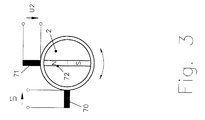
- Fig. 3 shows an embodiment with two fixed, on one Circumference arranged at a distance of 90 °, bipolar Pulse wire motion sensors 70, 71 and one with the rotating shaft 2 connected permanent magnet 72 according to dependent claim 8.
- bipolar pulse wire motion sensors deliver unipolar effects a voltage pulse during both the switching and the resetting process.
- the advantage of this arrangement is the implementation with the least possible Number of motion sensors.
- Fig. 4 shows an embodiment with two fixed, on one Circumference arranged at a distance of 180 °, bipolar Pulse wire motion sensors consisting of two sensor coils 90, 91, two permanent magnets 92, 93 assigned to sensor coil 90, two of the sensor coil 91 assigned permanent magnets 94, 95 and one with the rotary shaft 2 connected pulse wire 96 according to dependent claim 11.
- the sensor coil of the Pulse wire motion sensor separately from the pulse wire in a known manner arranged between two oppositely polarized permanent magnets.
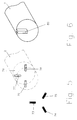
- FIG. 5 shows a mechanical arrangement of three motion sensors 73, 74, 75, a switching permanent magnet 77 and two reset permanent magnets 76, 78 according to dependent claim 7.
- the magnetically effective axes of Motion sensors and permanent magnets are radial to the axis of the rotary shaft 2 oriented.
- the permanent magnets attached to the end of the rotating shaft are in one Embedded shaft piece 79 made of magnetically non-conductive material, so that The structure of the magnetic fields remains unaffected by the material of the rotating shaft.
- An arrangement in this form allows the construction of an inventive one Angle of rotation sensor with small outer circumference.
- Fig. 6 shows a mechanical design according to dependent claim 10.
- One each Form a bipolar pulse wire motion sensor and two permanent magnets in a known manner a unit of which three correspond to the Motion sensors 73, 74, 75 in Fig. 5 are arranged fixed.
- the Magnetization of the motion sensors is caused by a movable, on the shaft attached flow guide 80 controlled.
- the magnetic flux of both Permanent magnets penetrate each other in opposite directions via air gaps Motion sensor (pulse wire and the sensor coil wound on it).
- the magnetic flux becomes one of the magnets amplified and the motion sensor magnetized. Accordingly, the Motion sensor magnetized in another direction when the flux guide on the other air gap is brought up.
- the advantage of this embodiment is in the particularly simple design of the movable parts of the Arrangement.
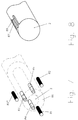
- FIG. 7 shows another mechanical arrangement of three Motion sensors 80 ', 81, 82, a switching permanent magnet 83 and two Reset permanent magnets 84, 85 according to dependent claim 7.
- the magnetic effective axes of motion sensors and permanent magnets oriented axially parallel to the rotary shaft 2.
- the attached at the end of the rotating shaft Permanent magnets are in a shaft piece 86 made of magnetically non-conductive material embedded so that the structure of the magnetic fields is unaffected by the material the rotating shaft remains.
- Fig. 8 shows a mechanical design according to dependent claim 9.
- One each unipolar (see FIG. 6) acting pulse wire motion sensor and two Permanent magnets form a unit of which three in a known manner corresponding to the motion sensors 80 ', 81, 82 in Fig. 7 fixed are arranged.
- the magnetization of the motion sensors is done by two movable flux guide pieces 87, 88 attached to the shaft 2 as in FIG. 6 described controlled.
- the advantage of this embodiment lies next to that particularly simple design of the movable parts of the Arrangement in the short design.
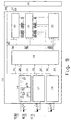
- Fig. 9 shows the execution of an electronic counter circuit 13 dependent claims 2, 3, 4, 5, 12, consisting of three identically designed Pulse shaping circuits 16, 17, 18, a control circuit 19, one settable up / down counter 22, a non-volatile read / write memory 21 and an evaluation and interface circuit 20.
- Each of the pulse shaping circuits consists of a diode 23, a charging capacitor 24, a Discharge resistor 25, an electronic switch 26 and a diode 27. Die generated by the voltage-generating movement sensors 6, 7, 8 Pulse voltages U1, U2, U3 are the three pulse shaping circuits 16, 17, 18 fed. Charges in the forward direction via the diode 23 Voltage pulse the charging capacitor 24.
- the capacitor voltage is the series circuit of electronic Switch 26 and discharge resistor 25 supplied.
- Logic signals "charging capacitor discharge "31, 32, 33 for discharging the charging capacitors are the supplied electronic switches from the control circuit 19. Via the diode 27 becomes a condenser voltage in the forward direction Auxiliary supply voltage formed on a line 34.
- the Auxiliary supply voltage is the supply voltage inputs of the Control circuit 19, the up / down counter 22 and the non-volatile memory 21 fed.
- the non-volatile memory is made in ferroelectric technology.
- Non-volatile read / write memory 21 as a static semiconductor memory in CMOS technology with a Buffer battery or a buffer capacitor executed. Since the Motion sensors do not require a supply voltage, this indicates Embodiment an advantageously low supply current for operation of the non-volatile memory, so that the backup batteries have a longer life Lifespan remain usable.
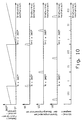
- the voltage pulses U1, U2, U3 cause one revolution of the shaft in three sectors I, II, III divided.
- the occurrence of a voltage pulse U1 shows when turning to the left, the transition of the shaft rotation angle from sector III to Sector I on, when turning to the right the transition from sector I to sector III.
- the angular position of the Rotary shaft can thus by evaluating the voltage pulses U1, U2, U3 given states taking into account past states U1 (-1), U2 (-1), U3 (-1) can be assigned to one of the sectors I, II or III.
- the number of shaft revolutions can be as follows, below shown, evaluation of the voltage pulses are counted.
- the state vector "last revolution state” Z and the logic signal “Counting direction” are stored in the non-volatile memory.
- the control sequence causes the up / down counter to contain the content of the non-volatile memory loaded, depending on the pulse voltage vector Y, State vector "last revolution state” Z and count direction bit RB incremented or decremented and back into the non-volatile memory is transferred back.
- Equations (G10) and (G11) state that each pulse U1 of the Motion sensor 6 with monotonous rotary movement of the rotary shaft 2 in positive or negative direction of rotation the up / down counter by the value "1" incremented or decremented.
- the equations (G12) and (G13) state that that after reversing the direction of rotation, if necessary, the pulses U2, U3 Motion sensors 7 and 8 for incrementing or decrementing the Revolution counter are evaluated.
- the evaluation and interface circuit 20 combines the measured value of the fine angle of rotation sensor and the value of the revolution counter stored in the non-volatile memory to form an absolute measured value for the angle of rotation. Since the relative position of the voltage-generating movement sensors 6, 7, 8 with respect to the position of the fine rotation angle sensor is subject to manufacturing and component tolerances, the value of the fine rotation angle sensor 3, which is in the non-volatile memory, must be determined in order to determine the absolute angular position WA of the rotary shaft 21 stored counter reading, the state vector "last state of revolution" Z and the count direction bit are evaluated.
- This evaluation also takes into account the transition states occurring in connection with a reversal of the direction of rotation according to equations (G12) and (G13); it synchronizes the information of the revolution counter with the angular position of the fine rotation angle sensor.
- the result is a corrected counter reading N 'as a function of the angular position of the fine rotation angle sensor, the state vector "last state of rotation” Z and the "counting direction" RB.
- the absolute angular position is determined by the evaluation and interface circuit 20 over the data interface with lines 14 of the parent Unit 15 fed.
- the transmission usually has to be set to a predetermined value a numerical value from the higher-level unit 15 in the non-volatile Memory of the rotation angle sensor provided.
- Fig. 11 shows an alternative graphical representation form of the in the Equations G1 to G14 described logical relationships for counting the Shaft revolutions in the form of a state diagram. After that is the Movement of the rotating shaft using four logic states S (1L) 100, S (1R) 101, S (2) 102, S (3) 103 and ten state transitions corresponding to the Shaft revolution shown in clockwise or counter-clockwise.
- the state transitions occur when the shaft rotates monotonically to the left 104, 107, 110 with incrementing the up / down counter at transition 104.
- the state transitions 106, 108, 111 occur with a monotonous clockwise rotation Decrement the up / down counter at transition 108.
- When changing direction of rotation state transitions 112 and 113 take place within sectors 1 and III without influencing counter or direction bit.
- State transition 105 When changing direction from Left turn after right turn with leaving sectors I and III State transition 105 with decrementing the counter.
- the direction bit logic "1" is set at the state transitions 107, 109, 110, 104, it becomes logic "0" set at the state transitions 105, 106, 108, 111. Die The direction bit is evaluated before the corresponding one is executed State transition, the update takes place afterwards.
Landscapes
- Physics & Mathematics (AREA)
- General Physics & Mathematics (AREA)
- Transmission And Conversion Of Sensor Element Output (AREA)
- Measurement Of Length, Angles, Or The Like Using Electric Or Magnetic Means (AREA)
Claims (12)
- Capteur d'angle de rotation (1) pour la mesure de la position angulaire d'un arbre rotatif (2) sur plus d'une rotation, constitué par un capteur d'angle de rotation précis (3) relié à l'arbre rotatif (2) et servant à réaliser la mesure absolue de la position angulaire de l'arbre rotatif (2) sur une rotation, et par un dispositif de comptage (4) servant à compter les rotations complètes de l'arbre rotatif (2), le dispositif de comptage (4) étant constitué par au moins deux capteurs de déplacement à fil à impulsions (70, 71) montés de façon fixe sur une circonférence de cercle, au moins un aimant permanent (72) et un circuit de montage électronique (13),
caractérisé en ce que
une mémoire d'écriture/lecture non volatile (21) est prévue pour la mémorisation du nombre des rotations de l'arbre, et une partie de l'énergie électrique, qui est délivrée par les capteurs de déplacement à fil à impulsions (70, 71) est envoyée au circuit de comptage électronique (13) pour l'alimentation en énergie. - Capteur d'angle de rotation selon la revendication 1,
caractérisé en ce que
à chaque capteur de déplacement à fil à impulsions est associé un circuit (16) de mise en forme d'impulsions constitué par un élément de chargement (24), auquel les impulsions de tension du capteur de déplacement sont envoyées par l'intermédiaire d'un élément de commutation (23), et un autre élément de commutation (27), au moyen duquel la tension de l'élément de chargement est envoyée à une unité (34) délivrant une tension d'alimentation auxiliaire. - Capteur d'angle de rotation selon la revendication 2,
caractérisé en ce que
les éléments de commutation (23, 27) sont réalisés sous la forme de diodes à semi-conducteurs et l'élément de chargement (24) est réalisé sous la forme d'un condensateur. - Capteur d'angle de rotation selon la revendication 2 ou 3,
caractérisé en ce que
le circuit (16) de mise en forme d'impulsions comporte un circuit série, qui est constitué par une résistance de décharge (25) et un interrupteur électronique (26) et auquel est envoyée la tension de l'élément de chargement (24). - Capteur d'angle de rotation selon l'une des revendications 1 à4
caractérisé en ce que
les éléments de la mémoire d'écriture/lecture non volatile (21) sont réalisés selon la technologie ferroélectrique sous la forme de dipôles cristallins, dont l'état de commutation est modifié par application d'un champ électrique. - Capteur d'angle de rotation selon la revendication 1
caractérisé en ce que
la mémoire d'écriture/lecture non volatile (21) est agencée sous la forme d'une mémoire à semi-conducteurs statique à laquelle une tension d'alimentation est envoyée à partir d'un accumulateur d'énergie. - Capteur d'angle de rotation selon l'une des revendications 1 à 6,
caractérisé en ce que
trois capteurs de déplacement à fil à impulsions (6, 7, 8, 73, 74, 75, 80', 81, 82) à action unipolaire, un aimant permanent de commutation (10, 77, 83) relié à l'arbre rotatif (2) et deux aimants permanents de rappel (11, 12, 76, 78, 84, 85) reliés à l'arbre de rotation sont prévus. - Capteur d'angle de rotation selon l'une des revendications 1 à 6,
caractérisé en ce que
deux capteurs de déplacement à fil à impulsions (70, 71) à action bipolaire et au moins un aimant permanent (72) relié à l'arbre rotatif (2) sont prévus. - Capteur d'angle de rotation selon l'une des revendications 1 à 6,
caractérisé en ce que
trois capteurs de déplacement à fil à impulsions (80', 81, 82) à action unipolaire, six aimants permanents fixes et deux pièces ferromagnétiques de guidage de flux (87, 88) reliées à l'arbre rotatif (2) sont prévus. - Capteur d'angle de rotation selon l'une des revendications 1 à 6
caractérisé en ce que
trois capteurs de déplacement à fil à impulsions (73, 74, 75) à action bipolaire, six aimants permanents fixes et une pièce ferromagnétique de guidage de flux (80), qui est reliée à l'arbre rotatif (2), sont prévus. - Capteur d'angle de rotation selon l'une des revendications 1 à 6,
caractérisé en ce que
une section de fil à impulsions relié à l'arbre rotatif (2), deux bobines de capteur (90, 91) montées fixes et quatre aimants permanents (92, 93, 94, 95) montés fixes sont prévus. - Capteur d'angle de rotation selon la revendication 2,
caractérisé en ce que
le circuit de comptage électronique (13) est constitué parla mémoire d'écriture/lecture non volatile (21),les circuits de mise en forme d'impulsions associés aux capteurs de déplacement,un compteur progressif/régressif (22), qui est relié à la mémoire d'écriture/lecture par l'intermédiaire de lignes de transmission de données D0; D1, ... Dnn (46, 47, 48,... 49),un circuit de commande (19), auquel les impulsions de tension des capteurs de déplacement sont envoyées par l'intermédiaire du circuit de mise en forme d'impulsions en tant que vecteur de tension d'impulsions Y = [Y1, Y2, Y3] (28, 29, 39), et qui est relié à la mémoire d'écriture/lecture par l'intermédiaire de signaux logiques "lecture à partir de la mémoire non volatile" (38), "inscription dans la mémoire non volatile" (37), "dispositif de comptage" (42), "dernier état de rotation", Z = [Z1, Z2, Z3] (43, 44, 45), et est relié au compteur progressif/régressif par l'intermédiaire de signaux logiques "cadence" (39), "comptage progressif/régressif" (40) et "positionnement du compteur" (41), et qui délivre les signaux logiques "déchargement" (31, 32, 33) aux circuits de mise en forme d'impulsions (16, 17, 18),un montage d'exploitation et d'interface (20), qui reçoit un signal logique "sortie prête" (36) de la part du montage de commande (19) et qui est relié à la mémoire non volatile par l'intermédiaire de signaux logiques "sortie du sens de comptage" (50), par l'intermédiaire du vecteur d'état "dernière sortie d'état de rotation" Z' = [Z'1, Z'2, Z'3], constitué par les signaux logiques Z1', Z2', 23' (51, 52, 53), et par l'intermédiaire d'un mot de données "sortie de rotation", constitué par les bits de données D0', D1', ... Dn' (54, 55, 56, ... 57).
Applications Claiming Priority (3)
| Application Number | Priority Date | Filing Date | Title |
|---|---|---|---|
| DE4407474A DE4407474C2 (de) | 1994-03-07 | 1994-03-07 | Drehwinkelsensor |
| DE4407474 | 1994-03-07 | ||
| PCT/DE1995/000308 WO1995024613A1 (fr) | 1994-03-07 | 1995-03-06 | Capteur d'angle de rotation |
Publications (2)
| Publication Number | Publication Date |
|---|---|
| EP0724712A1 EP0724712A1 (fr) | 1996-08-07 |
| EP0724712B1 true EP0724712B1 (fr) | 1999-07-28 |
Family
ID=6512026
Family Applications (1)
| Application Number | Title | Priority Date | Filing Date |
|---|---|---|---|
| EP95912128A Expired - Lifetime EP0724712B1 (fr) | 1994-03-07 | 1995-03-06 | Capteur d'angle de rotation |
Country Status (4)
| Country | Link |
|---|---|
| US (1) | US6084400A (fr) |
| EP (1) | EP0724712B1 (fr) |
| DE (2) | DE4407474C2 (fr) |
| WO (1) | WO1995024613A1 (fr) |
Cited By (8)
| Publication number | Priority date | Publication date | Assignee | Title |
|---|---|---|---|---|
| DE10259223B3 (de) * | 2002-11-20 | 2004-02-12 | Mehnert, Walter, Dr. | Positionsdetektor |
| DE102004013022B3 (de) * | 2004-03-16 | 2005-10-13 | Sew-Eurodrive Gmbh & Co. Kg | Abschnittszähler und Antrieb |
| DE102008030201A1 (de) | 2007-07-25 | 2009-01-29 | Dr. Johannes Heidenhain Gmbh | Drehgeber und Verfahren zu dessen Betrieb |
| US7598733B2 (en) | 2002-11-20 | 2009-10-06 | Walter Mehnert | Position detector |
| EP2515084A1 (fr) | 2011-04-19 | 2012-10-24 | Walter Dr. Mehnert | Procédé et agencement destinés à la détermination d'un mouvement utilisant un compteur à segments et un capteur de position précis |
| DE102012009962A1 (de) | 2012-05-19 | 2013-11-21 | Hengstler Gmbh | Batterieloser Zähler für strömende Medien |
| US8766625B2 (en) | 2007-08-17 | 2014-07-01 | Walter Mehnert | Linear segment or revolution counter with a ferromagnetic element |
| US9631948B2 (en) | 2012-04-15 | 2017-04-25 | Avago Technologies General Ip (Singapore) Pte. Ltd. | Method and arrangement for synchronizing a segment counter with a fine position sensor |
Families Citing this family (69)
| Publication number | Priority date | Publication date | Assignee | Title |
|---|---|---|---|---|
| DE19704867C1 (de) * | 1996-02-15 | 1998-08-13 | Kostal Leopold Gmbh & Co Kg | Antriebseinrichtung |
| ES2196421T3 (es) * | 1997-05-21 | 2003-12-16 | Bosch Gmbh Robert | Procedimiento para el funcionamiento de un sensor de posicion. |
| DE19902188A1 (de) * | 1999-01-21 | 2000-07-27 | Philips Corp Intellectual Pty | Anordnung zur Drehzahlmessung |
| DE19925884C2 (de) * | 1999-06-07 | 2001-09-20 | Tyco Electronics Logistics Ag | Magnetfeldsensor und seine Verwendung |
| DE19925882A1 (de) * | 1999-06-07 | 2000-12-21 | Tyco Electronics Logistics Ag | Magnetfeldsensor und seine Verwendung |
| DE19927851B4 (de) * | 1999-06-18 | 2008-11-13 | Danfoss Drives A/S | Verfahren zum Überwachen eines Drehwinkelaufnehmers an einer elektrischen Maschine |
| DE10001676C1 (de) * | 2000-01-12 | 2001-08-02 | Huebner Elmasch Ag | Elektronischer Umdrehungszähler |
| DE20005475U1 (de) * | 2000-03-23 | 2000-05-25 | Dr. Kohr GmbH & Co. Medizintechnik, 75233 Tiefenbronn | Massagegerät |
| DE10054470C2 (de) * | 2000-11-03 | 2003-07-17 | Siemens Ag | Drehstellungsgeber zum Erfassen einer Drehstellung |
| US6469499B2 (en) * | 2001-02-06 | 2002-10-22 | Delphi Technologies, Inc. | Apparatus and method for low power position sensing systems |
| DE10120735C2 (de) * | 2001-04-21 | 2003-07-24 | Oechsler Ag | Wellgetriebe |
| DE10145884B4 (de) * | 2001-09-18 | 2005-04-14 | Hella Kgaa Hueck & Co. | Elektronischer Winkelsensor |
| DE10151234B4 (de) | 2001-10-17 | 2004-07-08 | Siemens Ag | Umdrehungszähler zum Ermitteln einer Umdrehungszahl eines um eine Drehachse drehbaren Drehelements |
| DE10151243C5 (de) * | 2001-10-17 | 2005-06-09 | Siemens Ag | Umdrehungszähler |
| DE10158223B4 (de) * | 2001-11-16 | 2017-10-05 | Dr. Johannes Heidenhain Gmbh | Drehwinkel-Messgerät |
| US6628741B2 (en) * | 2001-11-20 | 2003-09-30 | Netzer Precision Motion Sensors Ltd. | Non-volatile passive revolution counter with reed magnetic sensor |
| CN1289911C (zh) * | 2002-03-08 | 2006-12-13 | Ntn株式会社 | 旋转检测器和采用它的防锁制动装置 |
| DE10315366B4 (de) * | 2003-04-03 | 2006-08-10 | Sew-Eurodrive Gmbh & Co. Kg | Vorrichtung und Synchronmotor |
| FR2857743B1 (fr) * | 2003-07-15 | 2005-10-21 | Skf Ab | Systeme de mesure de rotation |
| FR2861459B1 (fr) * | 2003-10-22 | 2006-02-24 | Skf Ab | Systeme de mesure de rotation haute resolution absolu multitour et roulement equipe d'un tel systeme. |
| EP1550845B2 (fr) * | 2003-12-24 | 2022-05-04 | Avago Technologies International Sales Pte. Limited | détecteur de position |
| DE102005006419B4 (de) * | 2004-05-27 | 2013-04-04 | Sew-Eurodrive Gmbh & Co. Kg | Segmentzähler und Verfahren |
| DE102004062448A1 (de) * | 2004-06-18 | 2006-01-19 | Valeo Schalter Und Sensoren Gmbh | Lenkwinkelsensor |
| DE102005023010B4 (de) | 2004-08-18 | 2025-03-27 | Sew-Eurodrive Gmbh & Co Kg | Segmentzähler, Lineargeber, Verfahren und Linearantrieb |
| US7659712B2 (en) * | 2004-10-13 | 2010-02-09 | Dresser, Inc. | System and method for process measurement |
| US7120220B2 (en) | 2004-12-23 | 2006-10-10 | Ramtron International Corporation | Non-volatile counter |
| US7142627B2 (en) * | 2004-12-23 | 2006-11-28 | Ramtron International Corporation | Counting scheme with automatic point-of-reference generation |
| US7411388B2 (en) * | 2005-08-30 | 2008-08-12 | Baker Hughes Incorporated | Rotary position sensor and method for determining a position of a rotating body |
| DE102005060519A1 (de) * | 2005-12-11 | 2007-06-14 | Valeo Schalter Und Sensoren Gmbh | Drehwinkelsensor und Drehwinkelsensorsystem |
| WO2007065496A1 (fr) | 2005-12-11 | 2007-06-14 | Valeo Schalter Und Sensoren Gmbh | Detecteur d'angle de rotation et système de detection de l'angle de rotation |
| US7648082B2 (en) * | 2005-11-28 | 2010-01-19 | Rain Bird Corporation | Irrigation rotor sensor |
| DE102006017865B4 (de) * | 2006-04-13 | 2012-04-12 | Sick Stegmann Gmbh | Vorrichtung zur Messung der absoluten Position eines Messobjekts |
| DE102006025906A1 (de) * | 2006-06-02 | 2007-12-06 | Robert Bosch Gmbh | Verfahren zur Erkennung der Sensorzuordnung innerhalb einer elektrischen Maschine |
| US7456629B2 (en) * | 2006-07-11 | 2008-11-25 | Continental Automotive Systems Us, Inc. | Rotary angle sensing system |
| DE102006038268A1 (de) * | 2006-08-09 | 2008-02-14 | Takata-Petri Ag | Vorrichtung zur berührungslosen Erkennung von Drehwinkeländerungen und Mehrfachumdrehungen |
| DE102007007764A1 (de) * | 2007-02-16 | 2008-08-21 | Dr. Johannes Heidenhain Gmbh | Drehgeber und Verfahren zu dessen Betrieb |
| US8497685B2 (en) * | 2007-05-22 | 2013-07-30 | Schlumberger Technology Corporation | Angular position sensor for a downhole tool |
| US20090035121A1 (en) * | 2007-07-31 | 2009-02-05 | Dresser, Inc. | Fluid Flow Modulation and Measurement |
| DE102007050898A1 (de) * | 2007-10-24 | 2009-04-30 | Continental Automotive Gmbh | Vorrichtung zum Ermitteln von Umdrehungen einer Welle |
| US7928724B2 (en) * | 2008-05-27 | 2011-04-19 | Honeywell International Inc. | Magnetic odometer with direction indicator systems and method |
| DE102009021081B4 (de) * | 2008-07-18 | 2017-07-06 | Asm Automation Sensorik Messtechnik Gmbh | Magnetischer Winkelsensor |
| US8384377B2 (en) * | 2009-10-30 | 2013-02-26 | Honeywell International Inc. | Self-powered magnetic tachometer for supplying a signal representative of rotational rate and absolute position |
| DE102010022154B4 (de) * | 2010-03-30 | 2017-08-03 | Avago Technologies General Ip (Singapore) Pte. Ltd. | Magnetischer Drehgeber |
| ES2732551T3 (es) | 2010-04-26 | 2019-11-25 | Nidec Avtron Automation Corp | Codificador absoluto |
| DE102010027607A1 (de) * | 2010-07-20 | 2012-01-26 | Bauer Spezialtiefbau Gmbh | In-Situ hergestellte Bodenmörtellamellen mit geometrischer Darstellung |
| JP2012198067A (ja) * | 2011-03-18 | 2012-10-18 | Hirose Electric Co Ltd | 回転運動または周回運動を検出する運動検出装置 |
| EP2797210A4 (fr) * | 2011-12-21 | 2016-01-13 | Yaskawa Denki Seisakusho Kk | Moteur, système de moteur, et encodeur de moteur |
| EP2623992A1 (fr) * | 2012-02-03 | 2013-08-07 | Siemens Aktiengesellschaft | Encodeur et son procédé de fonctionnement |
| DE102012008888A1 (de) | 2012-04-30 | 2013-10-31 | Fritz Kübler GmbH Zähl- und Sensortechnik | Energieautarker Multiturn-Drehgeber und Verfahren zur Ermittlung einer eindeutigen Position einer Geberwelle mit dem Multiturn-Drehgeber |
| EP2844955B1 (fr) | 2012-04-30 | 2016-05-11 | Fritz Kübler GmbH Zähl-und Sensortechnik | Capteur de rotation multi-tours autosuffisant en énergie et procédé de détermination sans ambiguïté la position d'un arbre capteur avec le capteur de rotation multi-tours |
| DE102012017071A1 (de) | 2012-04-30 | 2013-10-31 | Fritz Kübler GmbH Zähl- und Sensortechnik | Energieautarker Multiturn-Drehgeber und Verfahren zur Ermittlung einer eindeutigen Position einer Geberwelle mit dem Multiturn-Drehgeber |
| DE102012012874B4 (de) * | 2012-06-28 | 2019-06-19 | Sew-Eurodrive Gmbh & Co Kg | Anordnung zur Bestimmung einer Umdrehungsanzahl einer drehbar gelagerten Welle und Verfahren zur Bestimmung einer Umdrehungsanzahl einer drehbar gelagerten Welle |
| US9350216B2 (en) | 2012-12-28 | 2016-05-24 | Quicksilver Controls, Inc. | Integrated multi-turn absolute position sensor for high pole count motors |
| US9261382B2 (en) | 2014-05-22 | 2016-02-16 | General Electric Company | System and method for mechanical runout measurement |
| JP6557086B2 (ja) * | 2015-07-31 | 2019-08-07 | ファナック株式会社 | ロータリスイッチを備えた制御装置 |
| DE102017203683B4 (de) * | 2016-05-31 | 2023-02-23 | Avago Technologies International Sales Pte. Limited | Zählsensor mit korrekturfunktion |
| CN107655510B (zh) * | 2017-03-02 | 2023-06-06 | 哈尔滨工大特种机器人有限公司 | 一种多圈绝对值编码器及位置检测方法 |
| CN107367304A (zh) * | 2017-06-26 | 2017-11-21 | 深圳市普颂电子有限公司 | 判断流量计转子旋转转数与方向的方法及系统 |
| JP7068749B2 (ja) * | 2018-05-15 | 2022-05-17 | ヒロセ電機株式会社 | 回転検出装置 |
| CN111480285B (zh) * | 2018-06-28 | 2022-08-19 | 西门子股份公司 | 电子封签装置、电机组件及电子封签核验方法 |
| IT201800007113A1 (it) * | 2018-07-11 | 2020-01-11 | Metodo di rilevamento della posizione assoluta di un elemento girevole e trasduttore multigiro assoluto | |
| JP7289359B2 (ja) | 2019-02-06 | 2023-06-09 | フラバ ベスローテン ヴェンノーツハップ | 磁気センサ装置 |
| EP3792599B1 (fr) * | 2019-09-12 | 2023-05-03 | TE Connectivity Belgium BVBA | Dispositif de capteur pour mesurer la position rotationnelle d'un élément |
| US11662230B2 (en) | 2020-05-04 | 2023-05-30 | Saudi Arabian Oil Company | Recorder for shaft rotation verification |
| US12442664B2 (en) * | 2021-05-27 | 2025-10-14 | Panasonic Intellectual Property Management Co., Ltd. | Rotation detector and rotation detection method |
| WO2023044362A1 (fr) | 2021-09-16 | 2023-03-23 | Gatekeeper Systems, Inc. | Roue susceptible de détecter un sens de rotation |
| ES2994175T3 (en) * | 2022-04-06 | 2025-01-20 | Rvmagnetics A S | Physical quantity measurement system and/or position measurement with bistable magnetic wire, method of measurement |
| DE102022124159B4 (de) * | 2022-09-21 | 2024-04-11 | Fachhochschule Aachen, Körperschaft d. öffentl. Rechts | Positionssensorvorrichtung |
| US12209859B2 (en) | 2022-09-26 | 2025-01-28 | Caterpillar Inc. | Hollow center angular position sensor |
Family Cites Families (15)
| Publication number | Priority date | Publication date | Assignee | Title |
|---|---|---|---|---|
| FR2366572A1 (fr) * | 1976-03-19 | 1978-04-28 | Snecma | Chaine de mesure de vitesse de rotation auto-alimentee |
| DE2817169C2 (de) * | 1978-04-20 | 1986-10-23 | Robert Bosch Gmbh, 7000 Stuttgart | Einrichtung zur Abgabe von Impulsen |
| JPS5953506B2 (ja) * | 1978-06-13 | 1984-12-25 | 日産自動車株式会社 | 回転速度検出装置 |
| DE3006585C2 (de) * | 1980-02-22 | 1983-12-22 | Robert Bosch Gmbh, 7000 Stuttgart | Impulsgeber |
| DE8206731U1 (de) * | 1982-03-11 | 1982-07-15 | Robert Bosch Gmbh, 7000 Stuttgart | Sensor |
| DE3219491C2 (de) * | 1982-05-25 | 1985-10-31 | Brown, Boveri & Cie Ag, 6800 Mannheim | Anordnung zur Impulserzeugung für eine Drehzahl- und Positionsmessung hoher Auflösung an rotierenden Teilen von Maschinen |
| DE3225500A1 (de) * | 1982-07-08 | 1984-01-12 | Doduco KG Dr. Eugen Dürrwächter, 7530 Pforzheim | Magnetischer fuehler |
| DE3340129A1 (de) * | 1983-11-05 | 1985-05-15 | Robert Bosch Gmbh, 7000 Stuttgart | Schaltgeraet |
| EP0231474B1 (fr) * | 1985-12-16 | 1990-09-05 | Siemens Aktiengesellschaft | Dispositif de détermination du déplacement absolue |
| DE3729949A1 (de) * | 1987-09-07 | 1989-03-23 | Siemens Ag | Drehgeber mit impulsdraht-sensoren |
| DE58900315D1 (de) * | 1988-05-03 | 1991-10-31 | Siemens Ag | Verfahren zur ueberwachung von impulsdrahtsensoren eines umdrehungsgebers auf sensorleitungsbruch und schaltungsanordnung zur durchfuehrung des verfahrens. |
| DE3930345A1 (de) * | 1989-09-12 | 1991-03-21 | Ruhrkohle Ag | Impulsgeberanordnung zum simultieren von impulsfoermigen messwertgebersignalen |
| IT1240133B (it) * | 1990-03-16 | 1993-11-27 | Prima Electronics S.P.A. | Dispositivo trasduttore di posizione |
| DE4137092C2 (de) * | 1991-11-12 | 1995-05-24 | Walcher Mestechnik Gmbh | Verfahren zum Messen von Winkeln von mehr als 360 DEG |
| DE4224129A1 (de) * | 1992-07-22 | 1994-01-27 | Duerrwaechter E Dr Doduco | Induktiver Drehimpulsgeber |
-
1994
- 1994-03-07 DE DE4407474A patent/DE4407474C2/de not_active Expired - Fee Related
-
1995
- 1995-03-06 WO PCT/DE1995/000308 patent/WO1995024613A1/fr not_active Ceased
- 1995-03-06 EP EP95912128A patent/EP0724712B1/fr not_active Expired - Lifetime
- 1995-03-06 US US08/716,225 patent/US6084400A/en not_active Expired - Lifetime
- 1995-03-06 DE DE59506466T patent/DE59506466D1/de not_active Expired - Lifetime
Cited By (15)
| Publication number | Priority date | Publication date | Assignee | Title |
|---|---|---|---|---|
| DE10259223B3 (de) * | 2002-11-20 | 2004-02-12 | Mehnert, Walter, Dr. | Positionsdetektor |
| US7598733B2 (en) | 2002-11-20 | 2009-10-06 | Walter Mehnert | Position detector |
| DE102004013022B3 (de) * | 2004-03-16 | 2005-10-13 | Sew-Eurodrive Gmbh & Co. Kg | Abschnittszähler und Antrieb |
| DE102008030201A1 (de) | 2007-07-25 | 2009-01-29 | Dr. Johannes Heidenhain Gmbh | Drehgeber und Verfahren zu dessen Betrieb |
| EP2023093A2 (fr) | 2007-07-25 | 2009-02-11 | Dr. Johannes Heidenhain GmbH | Encodeur et son procédé de fonctionnement |
| EP2023093A3 (fr) * | 2007-07-25 | 2014-12-31 | Dr. Johannes Heidenhain GmbH | Encodeur et son procédé de fonctionnement |
| US8766625B2 (en) | 2007-08-17 | 2014-07-01 | Walter Mehnert | Linear segment or revolution counter with a ferromagnetic element |
| DE102007039050B4 (de) | 2007-08-17 | 2023-08-31 | Avago Technologies International Sales Pte. Limited | Linearsegment- oder Umdrehungszähler mit einem ferromagnetischen Element |
| DE102007039050B8 (de) | 2007-08-17 | 2024-02-15 | Avago Technologies International Sales Pte. Limited | Linearsegment- oder Umdrehungszähler mit einem ferromagnetischen Element |
| DE102011002179A1 (de) | 2011-04-19 | 2012-10-25 | Walter Mehnert | Verfahren und Anordnung zur Synchronisation eines Segmentzählers mit einem Feinpositionssensor |
| EP2515084A1 (fr) | 2011-04-19 | 2012-10-24 | Walter Dr. Mehnert | Procédé et agencement destinés à la détermination d'un mouvement utilisant un compteur à segments et un capteur de position précis |
| DE102011002179B4 (de) | 2011-04-19 | 2023-10-12 | Avago Technologies International Sales Pte. Limited | Verfahren und Anordnung zur Synchronisation eines Segmentzählers mit einem Feinpositionssensor |
| US9631948B2 (en) | 2012-04-15 | 2017-04-25 | Avago Technologies General Ip (Singapore) Pte. Ltd. | Method and arrangement for synchronizing a segment counter with a fine position sensor |
| DE102012009962A1 (de) | 2012-05-19 | 2013-11-21 | Hengstler Gmbh | Batterieloser Zähler für strömende Medien |
| WO2013174469A2 (fr) | 2012-05-19 | 2013-11-28 | Hengstler Gmbh | Compteur sans batterie pour milieux en écoulement |
Also Published As
| Publication number | Publication date |
|---|---|
| WO1995024613A1 (fr) | 1995-09-14 |
| DE4407474C2 (de) | 2000-07-13 |
| US6084400A (en) | 2000-07-04 |
| EP0724712A1 (fr) | 1996-08-07 |
| DE59506466D1 (de) | 1999-09-02 |
| DE4407474C1 (de) | 1995-05-24 |
Similar Documents
| Publication | Publication Date | Title |
|---|---|---|
| DE4407474C1 (de) | Drehwinkelsensor | |
| EP2844955B1 (fr) | Capteur de rotation multi-tours autosuffisant en énergie et procédé de détermination sans ambiguïté la position d'un arbre capteur avec le capteur de rotation multi-tours | |
| EP1565755B2 (fr) | Detecteur de position | |
| DE10259223B3 (de) | Positionsdetektor | |
| EP2221587B1 (fr) | Indicateur de position magnétique absolu | |
| EP0679868B1 (fr) | Capteur de position avec circuit d'évaluation | |
| EP0231474B1 (fr) | Dispositif de détermination du déplacement absolue | |
| DE112013002075T5 (de) | Multirotations-Drehgeber | |
| DE102007039051A1 (de) | Absoluter feinauflösender Segment- oder Umdrehungszähler | |
| DE102012008888A1 (de) | Energieautarker Multiturn-Drehgeber und Verfahren zur Ermittlung einer eindeutigen Position einer Geberwelle mit dem Multiturn-Drehgeber | |
| EP1959240A2 (fr) | Encodeur et son procédé de fonctionnement | |
| EP2159549B1 (fr) | Dispositif de mesure de la position relative entre une mesure matérialisée et une tête de lecture | |
| DE10054470C2 (de) | Drehstellungsgeber zum Erfassen einer Drehstellung | |
| DE4229610A1 (de) | Drehgeber mit absolutwert-positionserfassung | |
| EP0863384B1 (fr) | Circuit et procédé d'opération d'un capteur de position utilisant des éléments à effet Hall | |
| DE4306487A1 (en) | Detecting absolute displacement of object, e.g. servomotor shaft - operating micromachine with elements made from polycrystalline silicon in magnetic field as object moves, and storing relative positions of micromachine elements | |
| EP0550794B1 (fr) | Codeur de rotation avec détection de valeur absolue de position | |
| DE3804786C2 (fr) | ||
| DE3126806A1 (de) | Digitaler messsensor, seine verwendung und verfahren zu seiner herstellung | |
| DE102017203676B4 (de) | Magnetischer absoluter Positionssensor | |
| EP3924694B1 (fr) | Dispositif capteur et son procédé de fonctionnement | |
| EP0566923B1 (fr) | Dispositif pour mesurer sans contact la position axiale d'un objet tournant | |
| DE19632656A1 (de) | Verfahren und Vorrichtung zum berührungslosen Erfassen der Lage oder der Drehstellung eines Gegenstandes | |
| DE3740544A1 (de) | Einrichtung zur wandlung einer weg- oder winkelgroesse in eine elektrische inkrementale oder digitale groesse | |
| DE102005061347A1 (de) | Anordnung zur Messung des absoluten Drehwinkels einer Welle |
Legal Events
| Date | Code | Title | Description |
|---|---|---|---|
| PUAI | Public reference made under article 153(3) epc to a published international application that has entered the european phase |
Free format text: ORIGINAL CODE: 0009012 |
|
| 17P | Request for examination filed |
Effective date: 19960517 |
|
| AK | Designated contracting states |
Kind code of ref document: A1 Designated state(s): DE ES FR GB IT |
|
| 17Q | First examination report despatched |
Effective date: 19980603 |
|
| GRAG | Despatch of communication of intention to grant |
Free format text: ORIGINAL CODE: EPIDOS AGRA |
|
| GRAG | Despatch of communication of intention to grant |
Free format text: ORIGINAL CODE: EPIDOS AGRA |
|
| GRAH | Despatch of communication of intention to grant a patent |
Free format text: ORIGINAL CODE: EPIDOS IGRA |
|
| GRAH | Despatch of communication of intention to grant a patent |
Free format text: ORIGINAL CODE: EPIDOS IGRA |
|
| GRAA | (expected) grant |
Free format text: ORIGINAL CODE: 0009210 |
|
| AK | Designated contracting states |
Kind code of ref document: B1 Designated state(s): DE ES FR GB IT |
|
| PG25 | Lapsed in a contracting state [announced via postgrant information from national office to epo] |
Ref country code: ES Free format text: THE PATENT HAS BEEN ANNULLED BY A DECISION OF A NATIONAL AUTHORITY Effective date: 19990728 |
|
| ITF | It: translation for a ep patent filed | ||
| GBT | Gb: translation of ep patent filed (gb section 77(6)(a)/1977) |
Effective date: 19990729 |
|
| REF | Corresponds to: |
Ref document number: 59506466 Country of ref document: DE Date of ref document: 19990902 |
|
| ET | Fr: translation filed | ||
| PLBQ | Unpublished change to opponent data |
Free format text: ORIGINAL CODE: EPIDOS OPPO |
|
| PLBI | Opposition filed |
Free format text: ORIGINAL CODE: 0009260 |
|
| PLBF | Reply of patent proprietor to notice(s) of opposition |
Free format text: ORIGINAL CODE: EPIDOS OBSO |
|
| 26 | Opposition filed |
Opponent name: MEHNERT, WALTER DR. ET AL Effective date: 20000427 |
|
| XX | Miscellaneous (additional remarks) |
Free format text: MITEINSPRECHENDER//CO-OPPONENT: THEIL, THOMAS DR. WALDSTRASSE 9 85258 AUFHAUSEN. |
|
| PLBF | Reply of patent proprietor to notice(s) of opposition |
Free format text: ORIGINAL CODE: EPIDOS OBSO |
|
| PLBO | Opposition rejected |
Free format text: ORIGINAL CODE: EPIDOS REJO |
|
| APAC | Appeal dossier modified |
Free format text: ORIGINAL CODE: EPIDOS NOAPO |
|
| APAE | Appeal reference modified |
Free format text: ORIGINAL CODE: EPIDOS REFNO |
|
| APAC | Appeal dossier modified |
Free format text: ORIGINAL CODE: EPIDOS NOAPO |
|
| REG | Reference to a national code |
Ref country code: GB Ref legal event code: IF02 |
|
| APAC | Appeal dossier modified |
Free format text: ORIGINAL CODE: EPIDOS NOAPO |
|
| PLBN | Opposition rejected |
Free format text: ORIGINAL CODE: 0009273 |
|
| STAA | Information on the status of an ep patent application or granted ep patent |
Free format text: STATUS: OPPOSITION REJECTED |
|
| 27O | Opposition rejected |
Effective date: 20021030 |
|
| APAH | Appeal reference modified |
Free format text: ORIGINAL CODE: EPIDOSCREFNO |
|
| PGFP | Annual fee paid to national office [announced via postgrant information from national office to epo] |
Ref country code: GB Payment date: 20070323 Year of fee payment: 13 |
|
| PGFP | Annual fee paid to national office [announced via postgrant information from national office to epo] |
Ref country code: IT Payment date: 20070605 Year of fee payment: 13 |
|
| PGFP | Annual fee paid to national office [announced via postgrant information from national office to epo] |
Ref country code: FR Payment date: 20070321 Year of fee payment: 13 |
|
| GBPC | Gb: european patent ceased through non-payment of renewal fee |
Effective date: 20080306 |
|
| REG | Reference to a national code |
Ref country code: FR Ref legal event code: ST Effective date: 20081125 |
|
| PG25 | Lapsed in a contracting state [announced via postgrant information from national office to epo] |
Ref country code: FR Free format text: LAPSE BECAUSE OF NON-PAYMENT OF DUE FEES Effective date: 20080331 |
|
| PG25 | Lapsed in a contracting state [announced via postgrant information from national office to epo] |
Ref country code: GB Free format text: LAPSE BECAUSE OF NON-PAYMENT OF DUE FEES Effective date: 20080306 |
|
| PG25 | Lapsed in a contracting state [announced via postgrant information from national office to epo] |
Ref country code: IT Free format text: LAPSE BECAUSE OF NON-PAYMENT OF DUE FEES Effective date: 20080306 |
|
| PLAB | Opposition data, opponent's data or that of the opponent's representative modified |
Free format text: ORIGINAL CODE: 0009299OPPO |
|
| PGFP | Annual fee paid to national office [announced via postgrant information from national office to epo] |
Ref country code: DE Payment date: 20140327 Year of fee payment: 20 |
|
| REG | Reference to a national code |
Ref country code: DE Ref legal event code: R071 Ref document number: 59506466 Country of ref document: DE |