EP0724717B1 - Appareil et procede de transfert d'un echantillon fluide - Google Patents
Appareil et procede de transfert d'un echantillon fluide Download PDFInfo
- Publication number
- EP0724717B1 EP0724717B1 EP94931783A EP94931783A EP0724717B1 EP 0724717 B1 EP0724717 B1 EP 0724717B1 EP 94931783 A EP94931783 A EP 94931783A EP 94931783 A EP94931783 A EP 94931783A EP 0724717 B1 EP0724717 B1 EP 0724717B1
- Authority
- EP
- European Patent Office
- Prior art keywords
- reaction
- block
- detection
- program
- sample
- Prior art date
- Legal status (The legal status is an assumption and is not a legal conclusion. Google has not performed a legal analysis and makes no representation as to the accuracy of the status listed.)
- Expired - Lifetime
Links
- 238000000034 method Methods 0.000 title claims abstract description 79
- 239000012530 fluid Substances 0.000 title claims description 23
- 238000012546 transfer Methods 0.000 title description 26
- 238000006243 chemical reaction Methods 0.000 claims abstract description 309
- 238000001514 detection method Methods 0.000 claims abstract description 234
- 150000007523 nucleic acids Chemical class 0.000 claims abstract description 102
- 102000039446 nucleic acids Human genes 0.000 claims abstract description 100
- 108020004707 nucleic acids Proteins 0.000 claims abstract description 100
- 238000005382 thermal cycling Methods 0.000 claims abstract description 34
- 239000003380 propellant Substances 0.000 claims description 63
- 230000001939 inductive effect Effects 0.000 claims description 10
- 230000008016 vaporization Effects 0.000 claims description 8
- 230000006911 nucleation Effects 0.000 claims description 7
- 238000010899 nucleation Methods 0.000 claims description 7
- 238000009834 vaporization Methods 0.000 claims description 7
- 238000004891 communication Methods 0.000 claims description 6
- 238000010438 heat treatment Methods 0.000 abstract description 133
- 239000011541 reaction mixture Substances 0.000 abstract description 7
- 238000007619 statistical method Methods 0.000 abstract 1
- 239000000523 sample Substances 0.000 description 197
- 238000003199 nucleic acid amplification method Methods 0.000 description 75
- 230000003321 amplification Effects 0.000 description 74
- 230000001351 cycling effect Effects 0.000 description 39
- 230000009870 specific binding Effects 0.000 description 33
- 108020004414 DNA Proteins 0.000 description 30
- 102000053602 DNA Human genes 0.000 description 30
- 239000003153 chemical reaction reagent Substances 0.000 description 30
- YBJHBAHKTGYVGT-ZKWXMUAHSA-N (+)-Biotin Chemical compound N1C(=O)N[C@@H]2[C@H](CCCCC(=O)O)SC[C@@H]21 YBJHBAHKTGYVGT-ZKWXMUAHSA-N 0.000 description 26
- 239000012491 analyte Substances 0.000 description 18
- 239000000047 product Substances 0.000 description 18
- 238000003556 assay Methods 0.000 description 16
- 238000001816 cooling Methods 0.000 description 16
- 229960002685 biotin Drugs 0.000 description 13
- 235000020958 biotin Nutrition 0.000 description 13
- 239000011616 biotin Substances 0.000 description 13
- 238000012360 testing method Methods 0.000 description 13
- 238000012545 processing Methods 0.000 description 12
- 230000027455 binding Effects 0.000 description 11
- 230000008859 change Effects 0.000 description 11
- 239000004816 latex Substances 0.000 description 11
- 229920000126 latex Polymers 0.000 description 11
- ZLGYJAIAVPVCNF-UHFFFAOYSA-N 1,2,4-trichloro-5-(3,5-dichlorophenyl)benzene Chemical compound ClC1=CC(Cl)=CC(C=2C(=CC(Cl)=C(Cl)C=2)Cl)=C1 ZLGYJAIAVPVCNF-UHFFFAOYSA-N 0.000 description 10
- 238000004458 analytical method Methods 0.000 description 10
- 230000007246 mechanism Effects 0.000 description 10
- 230000001745 anti-biotin effect Effects 0.000 description 9
- 238000002360 preparation method Methods 0.000 description 9
- BDERNNFJNOPAEC-UHFFFAOYSA-N propan-1-ol Chemical compound CCCO BDERNNFJNOPAEC-UHFFFAOYSA-N 0.000 description 9
- 230000006870 function Effects 0.000 description 8
- 239000011521 glass Substances 0.000 description 8
- 239000002245 particle Substances 0.000 description 8
- 239000007787 solid Substances 0.000 description 8
- 239000000020 Nitrocellulose Substances 0.000 description 7
- 108091034117 Oligonucleotide Proteins 0.000 description 7
- 230000000295 complement effect Effects 0.000 description 7
- 238000004519 manufacturing process Methods 0.000 description 7
- 239000000203 mixture Substances 0.000 description 7
- 229920001220 nitrocellulos Polymers 0.000 description 7
- 108090000623 proteins and genes Proteins 0.000 description 7
- ORILYTVJVMAKLC-UHFFFAOYSA-N adamantane Chemical compound C1C(C2)CC3CC1CC2C3 ORILYTVJVMAKLC-UHFFFAOYSA-N 0.000 description 6
- 238000011109 contamination Methods 0.000 description 6
- 230000005284 excitation Effects 0.000 description 6
- 238000003384 imaging method Methods 0.000 description 6
- 230000003100 immobilizing effect Effects 0.000 description 6
- 239000000463 material Substances 0.000 description 6
- 239000011859 microparticle Substances 0.000 description 6
- 230000035772 mutation Effects 0.000 description 6
- 238000007789 sealing Methods 0.000 description 6
- 201000003883 Cystic fibrosis Diseases 0.000 description 5
- 108020005187 Oligonucleotide Probes Proteins 0.000 description 5
- 238000012408 PCR amplification Methods 0.000 description 5
- SMWDFEZZVXVKRB-UHFFFAOYSA-N Quinoline Chemical compound N1=CC=CC2=CC=CC=C21 SMWDFEZZVXVKRB-UHFFFAOYSA-N 0.000 description 5
- 238000000137 annealing Methods 0.000 description 5
- 239000011324 bead Substances 0.000 description 5
- DZBUGLKDJFMEHC-UHFFFAOYSA-N benzoquinolinylidene Natural products C1=CC=CC2=CC3=CC=CC=C3N=C21 DZBUGLKDJFMEHC-UHFFFAOYSA-N 0.000 description 5
- 230000005540 biological transmission Effects 0.000 description 5
- 239000003795 chemical substances by application Substances 0.000 description 5
- 210000003917 human chromosome Anatomy 0.000 description 5
- 238000009396 hybridization Methods 0.000 description 5
- 239000002751 oligonucleotide probe Substances 0.000 description 5
- 239000004033 plastic Substances 0.000 description 5
- 229920003023 plastic Polymers 0.000 description 5
- 230000008569 process Effects 0.000 description 5
- 235000018102 proteins Nutrition 0.000 description 5
- 102000004169 proteins and genes Human genes 0.000 description 5
- RLEFOSDUWZYGOS-UHFFFAOYSA-N 3-(4-Isopropylphenyl)propanal Chemical compound CC(C)C1=CC=C(CCC=O)C=C1 RLEFOSDUWZYGOS-UHFFFAOYSA-N 0.000 description 4
- TWRXJAOTZQYOKJ-UHFFFAOYSA-L Magnesium chloride Chemical compound [Mg+2].[Cl-].[Cl-] TWRXJAOTZQYOKJ-UHFFFAOYSA-L 0.000 description 4
- BUGBHKTXTAQXES-UHFFFAOYSA-N Selenium Chemical compound [Se] BUGBHKTXTAQXES-UHFFFAOYSA-N 0.000 description 4
- 239000007983 Tris buffer Substances 0.000 description 4
- 239000005018 casein Substances 0.000 description 4
- BECPQYXYKAMYBN-UHFFFAOYSA-N casein, tech. Chemical compound NCCCCC(C(O)=O)N=C(O)C(CC(O)=O)N=C(O)C(CCC(O)=N)N=C(O)C(CC(C)C)N=C(O)C(CCC(O)=O)N=C(O)C(CC(O)=O)N=C(O)C(CCC(O)=O)N=C(O)C(C(C)O)N=C(O)C(CCC(O)=N)N=C(O)C(CCC(O)=N)N=C(O)C(CCC(O)=N)N=C(O)C(CCC(O)=O)N=C(O)C(CCC(O)=O)N=C(O)C(COP(O)(O)=O)N=C(O)C(CCC(O)=N)N=C(O)C(N)CC1=CC=CC=C1 BECPQYXYKAMYBN-UHFFFAOYSA-N 0.000 description 4
- 235000021240 caseins Nutrition 0.000 description 4
- 239000007795 chemical reaction product Substances 0.000 description 4
- 238000010276 construction Methods 0.000 description 4
- HAAZLUGHYHWQIW-KVQBGUIXSA-N dGTP Chemical compound C1=NC=2C(=O)NC(N)=NC=2N1[C@H]1C[C@H](O)[C@@H](COP(O)(=O)OP(O)(=O)OP(O)(O)=O)O1 HAAZLUGHYHWQIW-KVQBGUIXSA-N 0.000 description 4
- 238000010586 diagram Methods 0.000 description 4
- TXCDCPKCNAJMEE-UHFFFAOYSA-N dibenzofuran Chemical compound C1=CC=C2C3=CC=CC=C3OC2=C1 TXCDCPKCNAJMEE-UHFFFAOYSA-N 0.000 description 4
- 230000000694 effects Effects 0.000 description 4
- 230000001965 increasing effect Effects 0.000 description 4
- 238000002372 labelling Methods 0.000 description 4
- 239000007788 liquid Substances 0.000 description 4
- -1 nucleotide triphosphates Chemical class 0.000 description 4
- 102000040430 polynucleotide Human genes 0.000 description 4
- 108091033319 polynucleotide Proteins 0.000 description 4
- 239000002157 polynucleotide Substances 0.000 description 4
- 239000011148 porous material Substances 0.000 description 4
- 238000003860 storage Methods 0.000 description 4
- 108091093088 Amplicon Proteins 0.000 description 3
- 244000025254 Cannabis sativa Species 0.000 description 3
- 102000012410 DNA Ligases Human genes 0.000 description 3
- 108010061982 DNA Ligases Proteins 0.000 description 3
- 102000016928 DNA-directed DNA polymerase Human genes 0.000 description 3
- 108010014303 DNA-directed DNA polymerase Proteins 0.000 description 3
- 230000001594 aberrant effect Effects 0.000 description 3
- 239000000853 adhesive Substances 0.000 description 3
- 239000000443 aerosol Substances 0.000 description 3
- 230000004520 agglutination Effects 0.000 description 3
- 229910052782 aluminium Inorganic materials 0.000 description 3
- XAGFODPZIPBFFR-UHFFFAOYSA-N aluminium Chemical compound [Al] XAGFODPZIPBFFR-UHFFFAOYSA-N 0.000 description 3
- 238000009835 boiling Methods 0.000 description 3
- 150000001875 compounds Chemical class 0.000 description 3
- 125000001295 dansyl group Chemical group [H]C1=C([H])C(N(C([H])([H])[H])C([H])([H])[H])=C2C([H])=C([H])C([H])=C(C2=C1[H])S(*)(=O)=O 0.000 description 3
- 238000011161 development Methods 0.000 description 3
- 238000006073 displacement reaction Methods 0.000 description 3
- 230000002255 enzymatic effect Effects 0.000 description 3
- ZMMJGEGLRURXTF-UHFFFAOYSA-N ethidium bromide Chemical compound [Br-].C12=CC(N)=CC=C2C2=CC=C(N)C=C2[N+](CC)=C1C1=CC=CC=C1 ZMMJGEGLRURXTF-UHFFFAOYSA-N 0.000 description 3
- 229960005542 ethidium bromide Drugs 0.000 description 3
- GNBHRKFJIUUOQI-UHFFFAOYSA-N fluorescein Chemical compound O1C(=O)C2=CC=CC=C2C21C1=CC=C(O)C=C1OC1=CC(O)=CC=C21 GNBHRKFJIUUOQI-UHFFFAOYSA-N 0.000 description 3
- 239000012634 fragment Substances 0.000 description 3
- PCHJSUWPFVWCPO-UHFFFAOYSA-N gold Chemical compound [Au] PCHJSUWPFVWCPO-UHFFFAOYSA-N 0.000 description 3
- 230000033001 locomotion Effects 0.000 description 3
- 238000010606 normalization Methods 0.000 description 3
- 238000011160 research Methods 0.000 description 3
- 229920002477 rna polymer Polymers 0.000 description 3
- 239000011669 selenium Substances 0.000 description 3
- 229910052711 selenium Inorganic materials 0.000 description 3
- 239000000126 substance Substances 0.000 description 3
- 239000000725 suspension Substances 0.000 description 3
- XLYOFNOQVPJJNP-UHFFFAOYSA-N water Substances O XLYOFNOQVPJJNP-UHFFFAOYSA-N 0.000 description 3
- FWMNVWWHGCHHJJ-SKKKGAJSSA-N 4-amino-1-[(2r)-6-amino-2-[[(2r)-2-[[(2r)-2-[[(2r)-2-amino-3-phenylpropanoyl]amino]-3-phenylpropanoyl]amino]-4-methylpentanoyl]amino]hexanoyl]piperidine-4-carboxylic acid Chemical compound C([C@H](C(=O)N[C@H](CC(C)C)C(=O)N[C@H](CCCCN)C(=O)N1CCC(N)(CC1)C(O)=O)NC(=O)[C@H](N)CC=1C=CC=CC=1)C1=CC=CC=C1 FWMNVWWHGCHHJJ-SKKKGAJSSA-N 0.000 description 2
- ISADKOKKVZYYMM-UHFFFAOYSA-N 9h-carbazole;thiophene Chemical compound C=1C=CSC=1.C1=CC=C2C3=CC=CC=C3NC2=C1 ISADKOKKVZYYMM-UHFFFAOYSA-N 0.000 description 2
- 230000004544 DNA amplification Effects 0.000 description 2
- NYHBQMYGNKIUIF-UUOKFMHZSA-N Guanosine Chemical compound C1=NC=2C(=O)NC(N)=NC=2N1[C@@H]1O[C@H](CO)[C@@H](O)[C@H]1O NYHBQMYGNKIUIF-UUOKFMHZSA-N 0.000 description 2
- OWXMKDGYPWMGEB-UHFFFAOYSA-N HEPPS Chemical compound OCCN1CCN(CCCS(O)(=O)=O)CC1 OWXMKDGYPWMGEB-UHFFFAOYSA-N 0.000 description 2
- 101000899111 Homo sapiens Hemoglobin subunit beta Proteins 0.000 description 2
- KFZMGEQAYNKOFK-UHFFFAOYSA-N Isopropanol Chemical compound CC(C)O KFZMGEQAYNKOFK-UHFFFAOYSA-N 0.000 description 2
- VVQNEPGJFQJSBK-UHFFFAOYSA-N Methyl methacrylate Chemical compound COC(=O)C(C)=C VVQNEPGJFQJSBK-UHFFFAOYSA-N 0.000 description 2
- 108091028043 Nucleic acid sequence Proteins 0.000 description 2
- 239000004677 Nylon Substances 0.000 description 2
- 229920005372 Plexiglas® Polymers 0.000 description 2
- 239000004743 Polypropylene Substances 0.000 description 2
- 229920002684 Sepharose Polymers 0.000 description 2
- 241000589500 Thermus aquaticus Species 0.000 description 2
- 241000589499 Thermus thermophilus Species 0.000 description 2
- 230000002547 anomalous effect Effects 0.000 description 2
- 239000000872 buffer Substances 0.000 description 2
- 238000001311 chemical methods and process Methods 0.000 description 2
- 238000004587 chromatography analysis Methods 0.000 description 2
- 238000004590 computer program Methods 0.000 description 2
- SUYVUBYJARFZHO-RRKCRQDMSA-N dATP Chemical compound C1=NC=2C(N)=NC=NC=2N1[C@H]1C[C@H](O)[C@@H](COP(O)(=O)OP(O)(=O)OP(O)(O)=O)O1 SUYVUBYJARFZHO-RRKCRQDMSA-N 0.000 description 2
- SUYVUBYJARFZHO-UHFFFAOYSA-N dATP Natural products C1=NC=2C(N)=NC=NC=2N1C1CC(O)C(COP(O)(=O)OP(O)(=O)OP(O)(O)=O)O1 SUYVUBYJARFZHO-UHFFFAOYSA-N 0.000 description 2
- RGWHQCVHVJXOKC-SHYZEUOFSA-J dCTP(4-) Chemical compound O=C1N=C(N)C=CN1[C@@H]1O[C@H](COP([O-])(=O)OP([O-])(=O)OP([O-])([O-])=O)[C@@H](O)C1 RGWHQCVHVJXOKC-SHYZEUOFSA-J 0.000 description 2
- NHVNXKFIZYSCEB-XLPZGREQSA-N dTTP Chemical compound O=C1NC(=O)C(C)=CN1[C@@H]1O[C@H](COP(O)(=O)OP(O)(=O)OP(O)(O)=O)[C@@H](O)C1 NHVNXKFIZYSCEB-XLPZGREQSA-N 0.000 description 2
- 238000013500 data storage Methods 0.000 description 2
- 238000004925 denaturation Methods 0.000 description 2
- 230000036425 denaturation Effects 0.000 description 2
- 238000001917 fluorescence detection Methods 0.000 description 2
- 239000007850 fluorescent dye Substances 0.000 description 2
- 229910052737 gold Inorganic materials 0.000 description 2
- 239000010931 gold Substances 0.000 description 2
- 238000003018 immunoassay Methods 0.000 description 2
- 230000001788 irregular Effects 0.000 description 2
- 238000007834 ligase chain reaction Methods 0.000 description 2
- 229910001629 magnesium chloride Inorganic materials 0.000 description 2
- 239000006249 magnetic particle Substances 0.000 description 2
- 239000011325 microbead Substances 0.000 description 2
- 239000013642 negative control Substances 0.000 description 2
- 239000002773 nucleotide Substances 0.000 description 2
- 229920001778 nylon Polymers 0.000 description 2
- 230000003287 optical effect Effects 0.000 description 2
- 230000036961 partial effect Effects 0.000 description 2
- 150000008300 phosphoramidites Chemical class 0.000 description 2
- 239000004417 polycarbonate Substances 0.000 description 2
- 238000003752 polymerase chain reaction Methods 0.000 description 2
- 229920001155 polypropylene Polymers 0.000 description 2
- 239000013641 positive control Substances 0.000 description 2
- 238000000926 separation method Methods 0.000 description 2
- 239000000243 solution Substances 0.000 description 2
- 239000000758 substrate Substances 0.000 description 2
- 230000008093 supporting effect Effects 0.000 description 2
- ZFXYFBGIUFBOJW-UHFFFAOYSA-N theophylline Chemical compound O=C1N(C)C(=O)N(C)C2=C1NC=N2 ZFXYFBGIUFBOJW-UHFFFAOYSA-N 0.000 description 2
- 229960000278 theophylline Drugs 0.000 description 2
- 239000012780 transparent material Substances 0.000 description 2
- KMEMIMRPZGDOMG-UHFFFAOYSA-N 2-cyanoethoxyphosphonamidous acid Chemical compound NP(O)OCCC#N KMEMIMRPZGDOMG-UHFFFAOYSA-N 0.000 description 1
- 108010037497 3'-nucleotidase Proteins 0.000 description 1
- 108010032595 Antibody Binding Sites Proteins 0.000 description 1
- 238000012935 Averaging Methods 0.000 description 1
- 108090001008 Avidin Proteins 0.000 description 1
- 229920002799 BoPET Polymers 0.000 description 1
- 241001155430 Centrarchus Species 0.000 description 1
- 241000498849 Chlamydiales Species 0.000 description 1
- 241000252203 Clupea harengus Species 0.000 description 1
- RYGMFSIKBFXOCR-UHFFFAOYSA-N Copper Chemical compound [Cu] RYGMFSIKBFXOCR-UHFFFAOYSA-N 0.000 description 1
- MIKUYHXYGGJMLM-GIMIYPNGSA-N Crotonoside Natural products C1=NC2=C(N)NC(=O)N=C2N1[C@H]1O[C@@H](CO)[C@H](O)[C@@H]1O MIKUYHXYGGJMLM-GIMIYPNGSA-N 0.000 description 1
- 241001643392 Cyclea Species 0.000 description 1
- NYHBQMYGNKIUIF-UHFFFAOYSA-N D-guanosine Natural products C1=2NC(N)=NC(=O)C=2N=CN1C1OC(CO)C(O)C1O NYHBQMYGNKIUIF-UHFFFAOYSA-N 0.000 description 1
- LTMHDMANZUZIPE-AMTYYWEZSA-N Digoxin Natural products O([C@H]1[C@H](C)O[C@H](O[C@@H]2C[C@@H]3[C@@](C)([C@@H]4[C@H]([C@]5(O)[C@](C)([C@H](O)C4)[C@H](C4=CC(=O)OC4)CC5)CC3)CC2)C[C@@H]1O)[C@H]1O[C@H](C)[C@@H](O[C@H]2O[C@@H](C)[C@H](O)[C@@H](O)C2)[C@@H](O)C1 LTMHDMANZUZIPE-AMTYYWEZSA-N 0.000 description 1
- 102000004190 Enzymes Human genes 0.000 description 1
- 108090000790 Enzymes Proteins 0.000 description 1
- 241000145821 Eragrostis tef Species 0.000 description 1
- LFQSCWFLJHTTHZ-UHFFFAOYSA-N Ethanol Chemical compound CCO LFQSCWFLJHTTHZ-UHFFFAOYSA-N 0.000 description 1
- 108091005904 Hemoglobin subunit beta Proteins 0.000 description 1
- 102100021519 Hemoglobin subunit beta Human genes 0.000 description 1
- 102000004856 Lectins Human genes 0.000 description 1
- 108090001090 Lectins Proteins 0.000 description 1
- 102000003960 Ligases Human genes 0.000 description 1
- 108090000364 Ligases Proteins 0.000 description 1
- 241000283973 Oryctolagus cuniculus Species 0.000 description 1
- 108010058846 Ovalbumin Proteins 0.000 description 1
- BELBBZDIHDAJOR-UHFFFAOYSA-N Phenolsulfonephthalein Chemical compound C1=CC(O)=CC=C1C1(C=2C=CC(O)=CC=2)C2=CC=CC=C2S(=O)(=O)O1 BELBBZDIHDAJOR-UHFFFAOYSA-N 0.000 description 1
- 239000004793 Polystyrene Substances 0.000 description 1
- FAPWRFPIFSIZLT-UHFFFAOYSA-M Sodium chloride Chemical compound [Na+].[Cl-] FAPWRFPIFSIZLT-UHFFFAOYSA-M 0.000 description 1
- 108010090804 Streptavidin Proteins 0.000 description 1
- 229930006000 Sucrose Natural products 0.000 description 1
- CZMRCDWAGMRECN-UGDNZRGBSA-N Sucrose Chemical compound O[C@H]1[C@H](O)[C@@H](CO)O[C@@]1(CO)O[C@@H]1[C@H](O)[C@@H](O)[C@H](O)[C@@H](CO)O1 CZMRCDWAGMRECN-UGDNZRGBSA-N 0.000 description 1
- 101710120037 Toxin CcdB Proteins 0.000 description 1
- JLCPHMBAVCMARE-UHFFFAOYSA-N [3-[[3-[[3-[[3-[[3-[[3-[[3-[[3-[[3-[[3-[[3-[[5-(2-amino-6-oxo-1H-purin-9-yl)-3-[[3-[[3-[[3-[[3-[[3-[[5-(2-amino-6-oxo-1H-purin-9-yl)-3-[[5-(2-amino-6-oxo-1H-purin-9-yl)-3-hydroxyoxolan-2-yl]methoxy-hydroxyphosphoryl]oxyoxolan-2-yl]methoxy-hydroxyphosphoryl]oxy-5-(5-methyl-2,4-dioxopyrimidin-1-yl)oxolan-2-yl]methoxy-hydroxyphosphoryl]oxy-5-(6-aminopurin-9-yl)oxolan-2-yl]methoxy-hydroxyphosphoryl]oxy-5-(6-aminopurin-9-yl)oxolan-2-yl]methoxy-hydroxyphosphoryl]oxy-5-(6-aminopurin-9-yl)oxolan-2-yl]methoxy-hydroxyphosphoryl]oxy-5-(6-aminopurin-9-yl)oxolan-2-yl]methoxy-hydroxyphosphoryl]oxyoxolan-2-yl]methoxy-hydroxyphosphoryl]oxy-5-(5-methyl-2,4-dioxopyrimidin-1-yl)oxolan-2-yl]methoxy-hydroxyphosphoryl]oxy-5-(4-amino-2-oxopyrimidin-1-yl)oxolan-2-yl]methoxy-hydroxyphosphoryl]oxy-5-(5-methyl-2,4-dioxopyrimidin-1-yl)oxolan-2-yl]methoxy-hydroxyphosphoryl]oxy-5-(5-methyl-2,4-dioxopyrimidin-1-yl)oxolan-2-yl]methoxy-hydroxyphosphoryl]oxy-5-(6-aminopurin-9-yl)oxolan-2-yl]methoxy-hydroxyphosphoryl]oxy-5-(6-aminopurin-9-yl)oxolan-2-yl]methoxy-hydroxyphosphoryl]oxy-5-(4-amino-2-oxopyrimidin-1-yl)oxolan-2-yl]methoxy-hydroxyphosphoryl]oxy-5-(4-amino-2-oxopyrimidin-1-yl)oxolan-2-yl]methoxy-hydroxyphosphoryl]oxy-5-(4-amino-2-oxopyrimidin-1-yl)oxolan-2-yl]methoxy-hydroxyphosphoryl]oxy-5-(6-aminopurin-9-yl)oxolan-2-yl]methoxy-hydroxyphosphoryl]oxy-5-(4-amino-2-oxopyrimidin-1-yl)oxolan-2-yl]methyl [5-(6-aminopurin-9-yl)-2-(hydroxymethyl)oxolan-3-yl] hydrogen phosphate Polymers Cc1cn(C2CC(OP(O)(=O)OCC3OC(CC3OP(O)(=O)OCC3OC(CC3O)n3cnc4c3nc(N)[nH]c4=O)n3cnc4c3nc(N)[nH]c4=O)C(COP(O)(=O)OC3CC(OC3COP(O)(=O)OC3CC(OC3COP(O)(=O)OC3CC(OC3COP(O)(=O)OC3CC(OC3COP(O)(=O)OC3CC(OC3COP(O)(=O)OC3CC(OC3COP(O)(=O)OC3CC(OC3COP(O)(=O)OC3CC(OC3COP(O)(=O)OC3CC(OC3COP(O)(=O)OC3CC(OC3COP(O)(=O)OC3CC(OC3COP(O)(=O)OC3CC(OC3COP(O)(=O)OC3CC(OC3COP(O)(=O)OC3CC(OC3COP(O)(=O)OC3CC(OC3COP(O)(=O)OC3CC(OC3COP(O)(=O)OC3CC(OC3CO)n3cnc4c(N)ncnc34)n3ccc(N)nc3=O)n3cnc4c(N)ncnc34)n3ccc(N)nc3=O)n3ccc(N)nc3=O)n3ccc(N)nc3=O)n3cnc4c(N)ncnc34)n3cnc4c(N)ncnc34)n3cc(C)c(=O)[nH]c3=O)n3cc(C)c(=O)[nH]c3=O)n3ccc(N)nc3=O)n3cc(C)c(=O)[nH]c3=O)n3cnc4c3nc(N)[nH]c4=O)n3cnc4c(N)ncnc34)n3cnc4c(N)ncnc34)n3cnc4c(N)ncnc34)n3cnc4c(N)ncnc34)O2)c(=O)[nH]c1=O JLCPHMBAVCMARE-UHFFFAOYSA-N 0.000 description 1
- 238000010521 absorption reaction Methods 0.000 description 1
- DPKHZNPWBDQZCN-UHFFFAOYSA-N acridine orange free base Chemical compound C1=CC(N(C)C)=CC2=NC3=CC(N(C)C)=CC=C3C=C21 DPKHZNPWBDQZCN-UHFFFAOYSA-N 0.000 description 1
- 239000002390 adhesive tape Substances 0.000 description 1
- AZDRQVAHHNSJOQ-UHFFFAOYSA-N alumane Chemical group [AlH3] AZDRQVAHHNSJOQ-UHFFFAOYSA-N 0.000 description 1
- 239000000427 antigen Substances 0.000 description 1
- 102000036639 antigens Human genes 0.000 description 1
- 108091007433 antigens Proteins 0.000 description 1
- 239000003125 aqueous solvent Substances 0.000 description 1
- 239000002981 blocking agent Substances 0.000 description 1
- 230000005587 bubbling Effects 0.000 description 1
- 235000014633 carbohydrates Nutrition 0.000 description 1
- 150000001720 carbohydrates Chemical class 0.000 description 1
- 229920002678 cellulose Polymers 0.000 description 1
- 239000000919 ceramic Substances 0.000 description 1
- 238000010367 cloning Methods 0.000 description 1
- 239000000084 colloidal system Substances 0.000 description 1
- 239000004020 conductor Substances 0.000 description 1
- 229910052802 copper Inorganic materials 0.000 description 1
- 239000010949 copper Substances 0.000 description 1
- 230000008878 coupling Effects 0.000 description 1
- 238000010168 coupling process Methods 0.000 description 1
- 238000005859 coupling reaction Methods 0.000 description 1
- OPTASPLRGRRNAP-UHFFFAOYSA-N cytosine Chemical group NC=1C=CNC(=O)N=1 OPTASPLRGRRNAP-UHFFFAOYSA-N 0.000 description 1
- 230000001419 dependent effect Effects 0.000 description 1
- 238000013461 design Methods 0.000 description 1
- LTMHDMANZUZIPE-PUGKRICDSA-N digoxin Chemical compound C1[C@H](O)[C@H](O)[C@@H](C)O[C@H]1O[C@@H]1[C@@H](C)O[C@@H](O[C@@H]2[C@H](O[C@@H](O[C@@H]3C[C@@H]4[C@]([C@@H]5[C@H]([C@]6(CC[C@@H]([C@@]6(C)[C@H](O)C5)C=5COC(=O)C=5)O)CC4)(C)CC3)C[C@@H]2O)C)C[C@@H]1O LTMHDMANZUZIPE-PUGKRICDSA-N 0.000 description 1
- 229960005156 digoxin Drugs 0.000 description 1
- LTMHDMANZUZIPE-UHFFFAOYSA-N digoxine Natural products C1C(O)C(O)C(C)OC1OC1C(C)OC(OC2C(OC(OC3CC4C(C5C(C6(CCC(C6(C)C(O)C5)C=5COC(=O)C=5)O)CC4)(C)CC3)CC2O)C)CC1O LTMHDMANZUZIPE-UHFFFAOYSA-N 0.000 description 1
- 229940079593 drug Drugs 0.000 description 1
- 239000003814 drug Substances 0.000 description 1
- 238000001035 drying Methods 0.000 description 1
- 230000009977 dual effect Effects 0.000 description 1
- 239000000975 dye Substances 0.000 description 1
- 238000005516 engineering process Methods 0.000 description 1
- 238000001704 evaporation Methods 0.000 description 1
- 238000002474 experimental method Methods 0.000 description 1
- 238000000605 extraction Methods 0.000 description 1
- 239000000835 fiber Substances 0.000 description 1
- 239000000499 gel Substances 0.000 description 1
- 238000001502 gel electrophoresis Methods 0.000 description 1
- 239000003365 glass fiber Substances 0.000 description 1
- 238000000227 grinding Methods 0.000 description 1
- 229940029575 guanosine Drugs 0.000 description 1
- 230000036541 health Effects 0.000 description 1
- 235000019514 herring Nutrition 0.000 description 1
- 238000005286 illumination Methods 0.000 description 1
- 238000010191 image analysis Methods 0.000 description 1
- 230000001976 improved effect Effects 0.000 description 1
- 230000000977 initiatory effect Effects 0.000 description 1
- 238000003780 insertion Methods 0.000 description 1
- 230000037431 insertion Effects 0.000 description 1
- 239000011810 insulating material Substances 0.000 description 1
- 239000012212 insulator Substances 0.000 description 1
- 230000002427 irreversible effect Effects 0.000 description 1
- 239000002523 lectin Substances 0.000 description 1
- 230000000670 limiting effect Effects 0.000 description 1
- 230000004807 localization Effects 0.000 description 1
- 230000013011 mating Effects 0.000 description 1
- 239000012528 membrane Substances 0.000 description 1
- 229910052751 metal Inorganic materials 0.000 description 1
- 239000002184 metal Substances 0.000 description 1
- 150000002739 metals Chemical class 0.000 description 1
- 238000013508 migration Methods 0.000 description 1
- 230000005012 migration Effects 0.000 description 1
- 238000012986 modification Methods 0.000 description 1
- 230000004048 modification Effects 0.000 description 1
- 229920005615 natural polymer Polymers 0.000 description 1
- 210000004940 nucleus Anatomy 0.000 description 1
- 239000013618 particulate matter Substances 0.000 description 1
- 230000035515 penetration Effects 0.000 description 1
- 230000002572 peristaltic effect Effects 0.000 description 1
- 239000012071 phase Substances 0.000 description 1
- 229960003531 phenolsulfonphthalein Drugs 0.000 description 1
- 230000003169 placental effect Effects 0.000 description 1
- 229920000515 polycarbonate Polymers 0.000 description 1
- 229920002223 polystyrene Polymers 0.000 description 1
- 238000005086 pumping Methods 0.000 description 1
- 125000002943 quinolinyl group Chemical group N1=C(C=CC2=CC=CC=C12)* 0.000 description 1
- 230000002829 reductive effect Effects 0.000 description 1
- 230000010076 replication Effects 0.000 description 1
- 230000004044 response Effects 0.000 description 1
- 230000000717 retained effect Effects 0.000 description 1
- PYWVYCXTNDRMGF-UHFFFAOYSA-N rhodamine B Chemical compound [Cl-].C=12C=CC(=[N+](CC)CC)C=C2OC2=CC(N(CC)CC)=CC=C2C=1C1=CC=CC=C1C(O)=O PYWVYCXTNDRMGF-UHFFFAOYSA-N 0.000 description 1
- 238000007788 roughening Methods 0.000 description 1
- YGSDEFSMJLZEOE-UHFFFAOYSA-M salicylate Chemical compound OC1=CC=CC=C1C([O-])=O YGSDEFSMJLZEOE-UHFFFAOYSA-M 0.000 description 1
- 229960001860 salicylate Drugs 0.000 description 1
- 238000012163 sequencing technique Methods 0.000 description 1
- 239000004449 solid propellant Substances 0.000 description 1
- 238000001179 sorption measurement Methods 0.000 description 1
- 229910001220 stainless steel Inorganic materials 0.000 description 1
- 239000010935 stainless steel Substances 0.000 description 1
- 238000010561 standard procedure Methods 0.000 description 1
- 239000005720 sucrose Substances 0.000 description 1
- 229920001059 synthetic polymer Polymers 0.000 description 1
- MPLHNVLQVRSVEE-UHFFFAOYSA-N texas red Chemical compound [O-]S(=O)(=O)C1=CC(S(Cl)(=O)=O)=CC=C1C(C1=CC=2CCCN3CCCC(C=23)=C1O1)=C2C1=C(CCC1)C3=[N+]1CCCC3=C2 MPLHNVLQVRSVEE-UHFFFAOYSA-N 0.000 description 1
- 238000013519 translation Methods 0.000 description 1
- 239000001226 triphosphate Substances 0.000 description 1
- 235000011178 triphosphate Nutrition 0.000 description 1
- 238000002604 ultrasonography Methods 0.000 description 1
- 239000012808 vapor phase Substances 0.000 description 1
- 230000003612 virological effect Effects 0.000 description 1
Images


Classifications
-
- B—PERFORMING OPERATIONS; TRANSPORTING
- B01—PHYSICAL OR CHEMICAL PROCESSES OR APPARATUS IN GENERAL
- B01L—CHEMICAL OR PHYSICAL LABORATORY APPARATUS FOR GENERAL USE
- B01L7/00—Heating or cooling apparatus; Heat insulating devices
- B01L7/52—Heating or cooling apparatus; Heat insulating devices with provision for submitting samples to a predetermined sequence of different temperatures, e.g. for treating nucleic acid samples
-
- B—PERFORMING OPERATIONS; TRANSPORTING
- B01—PHYSICAL OR CHEMICAL PROCESSES OR APPARATUS IN GENERAL
- B01L—CHEMICAL OR PHYSICAL LABORATORY APPARATUS FOR GENERAL USE
- B01L3/00—Containers or dishes for laboratory use, e.g. laboratory glassware; Droppers
- B01L3/50—Containers for the purpose of retaining a material to be analysed, e.g. test tubes
- B01L3/502—Containers for the purpose of retaining a material to be analysed, e.g. test tubes with fluid transport, e.g. in multi-compartment structures
-
- G—PHYSICS
- G01—MEASURING; TESTING
- G01N—INVESTIGATING OR ANALYSING MATERIALS BY DETERMINING THEIR CHEMICAL OR PHYSICAL PROPERTIES
- G01N35/00—Automatic analysis not limited to methods or materials provided for in any single one of groups G01N1/00 - G01N33/00; Handling materials therefor
- G01N2035/00178—Special arrangements of analysers
- G01N2035/00237—Handling microquantities of analyte, e.g. microvalves, capillary networks
-
- G—PHYSICS
- G01—MEASURING; TESTING
- G01N—INVESTIGATING OR ANALYSING MATERIALS BY DETERMINING THEIR CHEMICAL OR PHYSICAL PROPERTIES
- G01N35/00—Automatic analysis not limited to methods or materials provided for in any single one of groups G01N1/00 - G01N33/00; Handling materials therefor
- G01N2035/00346—Heating or cooling arrangements
- G01N2035/00356—Holding samples at elevated temperature (incubation)
- G01N2035/00366—Several different temperatures used
-
- G—PHYSICS
- G01—MEASURING; TESTING
- G01N—INVESTIGATING OR ANALYSING MATERIALS BY DETERMINING THEIR CHEMICAL OR PHYSICAL PROPERTIES
- G01N35/00—Automatic analysis not limited to methods or materials provided for in any single one of groups G01N1/00 - G01N33/00; Handling materials therefor
- G01N2035/00346—Heating or cooling arrangements
- G01N2035/00356—Holding samples at elevated temperature (incubation)
- G01N2035/00376—Conductive heating, e.g. heated plates
-
- G—PHYSICS
- G01—MEASURING; TESTING
- G01N—INVESTIGATING OR ANALYSING MATERIALS BY DETERMINING THEIR CHEMICAL OR PHYSICAL PROPERTIES
- G01N35/00—Automatic analysis not limited to methods or materials provided for in any single one of groups G01N1/00 - G01N33/00; Handling materials therefor
- G01N35/00584—Control arrangements for automatic analysers
- G01N35/00722—Communications; Identification
- G01N35/00732—Identification of carriers, materials or components in automatic analysers
- G01N2035/00742—Type of codes
- G01N2035/00752—Type of codes bar codes
-
- G—PHYSICS
- G01—MEASURING; TESTING
- G01N—INVESTIGATING OR ANALYSING MATERIALS BY DETERMINING THEIR CHEMICAL OR PHYSICAL PROPERTIES
- G01N35/00—Automatic analysis not limited to methods or materials provided for in any single one of groups G01N1/00 - G01N33/00; Handling materials therefor
- G01N35/10—Devices for transferring samples or any liquids to, in, or from, the analysis apparatus, e.g. suction devices, injection devices
- G01N35/1095—Devices for transferring samples or any liquids to, in, or from, the analysis apparatus, e.g. suction devices, injection devices for supplying the samples to flow-through analysers
-
- Y—GENERAL TAGGING OF NEW TECHNOLOGICAL DEVELOPMENTS; GENERAL TAGGING OF CROSS-SECTIONAL TECHNOLOGIES SPANNING OVER SEVERAL SECTIONS OF THE IPC; TECHNICAL SUBJECTS COVERED BY FORMER USPC CROSS-REFERENCE ART COLLECTIONS [XRACs] AND DIGESTS
- Y10—TECHNICAL SUBJECTS COVERED BY FORMER USPC
- Y10S—TECHNICAL SUBJECTS COVERED BY FORMER USPC CROSS-REFERENCE ART COLLECTIONS [XRACs] AND DIGESTS
- Y10S435/00—Chemistry: molecular biology and microbiology
- Y10S435/808—Optical sensing apparatus
Definitions
- the present invention relates generally to methods for fluid transfer, and in particular to a method for transfering amplified nucleic acid from a reaction chamber to a detection chamber within a closed and scaled container.
- nucleic acid amplification methods have been used in clinical diagnostics and in typing and quantifying DNA and RNA for cloning and sequencing.
- thermal cycling devices Devices for performing nucleic acid amplification reactions are known generally as thermal cycling devices or thermal cyclers.
- One example of such a device is described in published PCT Application, WO 92/20778.
- the PCT application's cycling device is useful in performing DNA amplification by techniques.
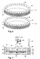
- the device described in WO 92/20778 includes a ring-shaped holder having a plurality of wells for accepting pipette tips containing samples. The samples are contained within the tips by heat sealing an open end of each tip. Means are provided for heating and cooling the ring, thereby allowing the device to cyclically heat and cool samples in the pipette tips.
- the means for cooling the ring includes a fan for drawing cool air over the ring, and cooling fins positioned radially inward from the ring to assist in directing cool air over the ring.
- PCR polymerase chain reaction
- LCR ligase chain reaction
- Amplification of nucleic acids using such methods is usually performed in a closed reaction vessel such as a snap-top vial or a sealable pipette as disclosed in WO 92/20778. After the amplification reaction is completed, the reaction vessel is opened, and the amplified product is transferred to a detection apparatus where standard detection methodologies are used.
- a closed reaction vessel such as a snap-top vial or a sealable pipette as disclosed in WO 92/20778.
- the amplified product is detected by denaturing the double stranded amplification products and treating the denatured strands with one or more hybridizing probes attached to a detectable label.
- the unhybridized labelled probes usually must be separated from the hybridized labelled probe, and this requires an extra separation step.
- the amplification products may be detected by gels stained with ethidium bromide. Thus, 32 P tracings; enzyme immunoassay [Keller et al., J. Clin.
- contamination may involve the work areas and equipment used for sample preparation, reaction reagent preparation, amplification, and analysis of the reaction products. Such contamination may also occur through contact transfer (carryover), or by aerosol generation.
- Probe hybridization techniques typically require denaturing the extension products, annealing the probe, and in some cases, separating excess probe from the reaction mixture.
- Gel electrophoresis is also disadvantageous because it is an impractical detection method if rapid results are desired.
- US Patent 5,229,297 and corresponding EP 0 381 501 A2 discloses a cuvette for carrying out amplification and detection of nucleic acid material in a closed environment to reduce the risk of contamination.
- the cuvette is a closed device having compartments that are interconnected by a series of passageways. Some of the compartments are reaction compartments for amplifying DNA strands, and some of the compartments are detection compartments having a detection site for detecting amplified DNA. Storage compartments may also be provided for holding reagents. Samples of nucleic acid materials, along with reagents from the storage compartments, are loaded into the reaction compartments via the passageways.
- the passageways leading from the storage compartment are provided with one-way check valves to prevent amplified products from backflowing into the storage compartment.
- the sample is amplified in the reaction compartment, and the amplified products are transferred through the interconnecting passageways to detection sites in the detection compartment by applying external pressure to the flexible compartment walls to squeeze the amplified product from the reaction compartments through the passageways and into the detection compartments.
- the cuvette may be provided with a piston arrangement to pump reagents and/or amplified products from the reaction compartments to the detection compartment.
- the cuvette disclosed in EP 0 381 501 A2 provides a closed reaction and detection environment, it has several significant shortcomings.
- the multiple compartments, multiple passageways, check valves and pumping mechanisms present a relatively complicated structure that requires some effort to manufacture.
- the shape and configuration of the cuvette disclosed in EP 0 381 501 A2 do not allow it to be readily inserted into conventional thermal cycling devices.
- the fluid transfer methods utilized by the cuvette call for a mechanical external pressure source, such as a roller device applied to flexible side walls or the displacement of small pistons.
- Conventional thermal cycling devices are not readily adapted to include such external pressure sources.
- the apparatus described in this reference is quite limited in terms of throughput of the disclosed devices. The system does not provide the desired flexibility for manufacturing.
- French patent publication No. FR 2 672 301 discloses a similar hermetically closed test device for amplification of DNA. It also has multiple compartments and passages through which sample and/or reagents are transferred.
- the motive forces for fluid transport are described as hydraulic, magnetic displacement, passive capillarity, thermal gradient, peristaltic pump and mechanically induced pressure differential (e.g. squeezing).
- Higuchi et al. Bio/Technology, 10 :413-417 (1992) describe a method for performing PCR amplification and detection of amplified nucleic acid in an unopened reaction vessel.
- Higuchi et al. teach that simultaneous amplification and detection is performed by adding ethidium bromide to the reaction vessel and the reaction reagents. The amplified nucleic acid produced in the amplification reaction is then detected by increased fluorescence produced by ethidium bromide binding to ds-DNA. The authors report that the fluorescence is measured by directing excitation through the walls of the amplification reaction vessel before, after or during thermal cycling.
- US Patent 5,210,015 also discloses a method of amplifying and detecting target nucleic acid wherein detection of the target takes place during a PCR amplification reaction.
- the reference teaches adding to the reaction mixture labeled oligonucleotide probes capable of annealing to the target, along with unlabeled oligonucleotide primer sequences.
- labeled oligonucleotide fragments are released by the 5' to 3' nuclease activity of a polymerase in the reaction mixture. The presence of target in the sample is thus detected by the release of labeled fragments from hybridized duplexes.
- WO 93/20240 also discloses a reaction vessel wherein amplification and detection are accomplished in the same vessel. Amplification products are captured on an optic element via specific binding to immobilized capture reagents. Combination of the amplification product with the capture reagent brings a fluorescent label within the penetration depth of an evanescent wave set up in the optic element. A change in fluorescence results from the coupling of the fluorescent label and is detected.
- the present invention provides a method for transferring a nucleic acid containing sample between a reaction chamber and a detection chamber relying on a different motive force for fluid transport than disclosed in any of the above art, in particular EP 0 381 501 and FR 2 672 301, said motive force being effectively utilized by way of a particular reaction chamber construction also not taught by the above art.
- the present invention is directed to a method for transferring a nucleic acid containing fluid sample (38) between a reaction chamber (30) and a detection chamber (32) within a device, comprising the steps of:
- the elongated reaction chamber may be of tubular construction having at least one or two longitudinal segments and being closed at one end and having an opening into the detection chamber at the opposite end.
- the propellant which may be any substance which can be induced to expand, may be the reaction sample itself or it may be a distinct substance lodged at or near the closed end of the reaction chamber. Ideally, the propellant may be induced to expand by a non-mechanical stimulus, such as light or heat. Expansion of a propellant should be distinguished from mechanical pressure increases arising from non-expansion events, such as hydraulic pressure or deformable septums.
- expansion of the propellant may encompass a phase change, such as the vaporization of a liquid to a gas.
- a phase change such as the vaporization of a liquid to a gas.
- a nucleation site may include inert particulate matter, such as boiling chips or glass or plastic microbeads, in the range of about 1.0 to 0.1mm in diameter, or a grooved, ridged or roughened surface inside the reaction chamber.
- the nucleation site is localized at or near the bottom of the reaction sample to more efficiently force the sample from the reaction chamber.
- the use of the method of the invention is for transferring a reaction sample containing nucleic acid that has been amplified by a thermal cycling process such as the ligase chain reaction or the polymerase chain reaction to a detection chamber without opening the sealed reaction/detection unit, thereby avoiding or significantly reducing the possibility of contamination of the work area by amplified nucleic-acid.
- a cycling reaction can be effected by applying intermittent heat to a first longitudinal segment and transfer can be effected by applying heat to a second longitudinal segment closer to the closed end.
- the means for applying heat to the two segments may be the same or different.
- cycling can be effected by intermittently applying a first maximum amount of heat, and transfer can be effected by applying heat in excess of said first maximum to "superheat" the propellant.
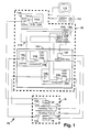
- FIG. 1 is a generalized schematic diagram of an amplification and detection apparatus configured in accordance with the invention.
- the apparatus 10 includes a thermal cycling device 16, including first and second heating element tiers 17 and 18 and associated thermosensors 122, 123, a fan motor 19 and a detection system 22, each of which will be described in more detail below.
- the apparatus 10 also includes a computer controller 26 coupled to the thermal cycling device 16.
- the thermal cycling device 16 under control of the computer 26 which sends independent signals to each of heater tier 1 (17) and heater tier 2 (18), is capable of independently delivering prescribed temperature(s) to localized segments of reaction containers housed inside the thermal cycler device 16, in order to amplify and/or transfer target nucleic acid present in the reaction samples. Details of the computer control of the device 16 are described in later sections.
- the apparatus 10 also includes a plurality of reaction/detection units 20 (see Figures 2-3).
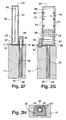
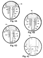
- the units 20 have a two-part, sealable construction that includes a reaction chamber 30 and a detection chamber 32, as shown in Figures 2A to 2H and 3A to 3D.
- the reaction chamber 30 houses the reaction sample for carrying out the desired amplification reactions.
- the detection chamber 32 is provided with means for generating a detectable indication of the results of the amplification reaction. Specific aspects and variations of these reaction/detection units 20 are described in detail later in this disclosure.
- the amplification reaction methods begin by inserting a reaction sample 38 into the reaction chamber 30, along with desired amplification reagents.
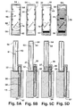
- the detection chamber 32 is then mated with the reaction chamber 30 to form the sealed unit 20 which is then placed into the heating tiers 17, 18 of the thermal cycling device 16 as best shown in Fig 2F and 5A-5D.
- the unit 20 remains sealed, thus providing a closed environment for carrying out both amplification and detection.
- the computer 26 controls the temperature settings and the timing of any temperature cycles, depending on the type of amplification reaction that is being performed.
- the computer 26 is programmed to take the heating tiers through one or more cycles of a high/denaturing temperature, followed by a low/annealing temperature. Where two tiers are provided, the computer 26 is capable of controlling the temperature of the upper heating tier 17 independently of the lower heating tier 18, although they may also follow identical protocols.
- the reaction sample is transferred from the reaction chamber 30 to the detection chamber 32 of the sealed unit 20.
- the reaction sample is preferably transferred by expanding a propellant in the reaction chamber 30 to force the sample and reagents into the detection chamber.
- the detection chamber 32 includes detection means for generating a detectable indication of the results of the amplification reaction.
- the detection means includes a support 60 having one or more capture sites 74 for immobilizing and accumulating amplified target nucleic acid present in the reaction sample 38.
- the immobilized amplified target nucleic acid is associated with a detectable indicator at the capture sites 74, and this indicator is detected and analyzed by the detection system 22 and the computer 26.
- the results of the amplification reaction are detected and analyzed by the detection system 22 and the computer controller 26.
- the detectable label is preferably a visible label, but other detectable labels, such as UV, IR or fluorescent labels, are also possible.
- the preferred detection system 22 generates a video image of the support 60 and includes a video camera 100 and a light source 104 (both shown in Figures 7 and 8A to 8D) for illuminating the support 60. An image of the support 60 is provided to the camera 100, either directly or by reflection, and the camera 100 generates a video image which is fed to the computer 26. For simplicity, visible labels will be discussed further.
- the detection system 22 should include a light source 104 for illuminating the detection means 60 and a camera 100 for creating video images of the detection means 60.
- the camera lens may be pointed directly at the detection means 60, or a mirror may be provided for reflecting an image of the detection means 60 to the camera lens.
- the detection system 22 includes a camera 100, a camera lens 102, a light souree 104, a mirror 106 and a motor 108 (preferably a stepper motor) coupled to the mirror 106.
- the light source 104 is positioned such that the camera lens 102 measures the colorimetric signals reflected from the support 61.
- the camera 100 and the mirror 106 are positioned axially with respect to the heating rings 90, 92, and the mirror 106 is positioned at an angle such that it reflects an image of the porous support 61 to the camera lens 102.
- the camera 100 is stationary, and the mirror 106 is rotated by the motor 108 under computer control to successively present an image of the strip 61 of each detection chamber 32 to the camera lens 102.
- the camera 100 generates a video image of the strip 61 of each detection chamber 32 and passes this image to the computer 26 for analysis.
- the software for analyzing this image is described later in the Video Processing section.
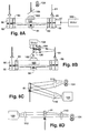
- FIG 8A illustrates another configuration of the detection system 22.
- This detection system includes a camera 100, a camera lens 102, a light source 104, a mirror 106, and a motor 109 coupled to the heating rings 90, 92.
- the light source 104 is positioned such that the camera lens 102 measures the colorimetric signals reflected from the support 61.
- the camera 100 and the mirror 106 are positioned axially with respect to the heating rings 90, 92, and the mirror 106 is positioned at an angle chosen so that it reflects an image of the support 61 to the camera lens 102.
- the camera 100 and the mirror 106 are stationary, and the heating rings 90, 92 are rotated by the motor 109 under computer control to successively move each detection means into view to present an image of the strip 61 of each detection chamber 32 to the mirror 106 which reflects the image to the camera lens 102.
- the camera 100 generates a video image of the support 61 of each detection chamber 32 and passes this image to the computer 26 for analysis.
- the camera lens 100 can be pointed directly at the support 61, thus eliminating the need for the mirror 106.
- the light source may be inside the ring while the camera is outside the ring, or vice versa.
- a reflectance fluorescence detection system is provided with a camera 100, a camera lens 102, a light source 104, an excitation filter 110 and an emission filter 112.
- the light source 104 and the camera 100 are positioned such that the camera lens 102 receives the fluorescent signals emitted from the support 61 in the detection chamber 32.
- the excitation filter 110 is positioned between the light source 104 and the support 61, and the emission filter 112 is positioned between the support 61 and the camera lens 102.
- FIG 8D another fluorescence detection system is provided with a camera 100, a camera lens 102, a light source 104, an excitation filter 110 and an emission filter 112.
- the light source 104 and the camera 100 are positioned such that the support 61 is between the light source 104 and the camera 100.
- the camera lens 102 receives the fluorescent signals transmitted through the support 61.
- the excitation filter 110 is positioned between the light source 104 and the support 61
- the emission filter 112 is positioned between the support 61 and the camera lens 102. Circuitry suitable for transmission detection is generally known.
- detection systems could utilize either the transmission or reflectance methods shown in Figures 8C and 8D; and either method for presenting successive detection means 60 to the camera.
- the detection systems could incorporate the rotating mirror and motor shown in Figure 8B, or the rotating heating rings 90, 92 and motor shown in Figure 8A (with or without the mirror).
- the computer controller 26 may be implemented as an IBM AT-compatible personal computer having a monitor 113, keyboard 114 and data storage means.
- the computer 26 includes an image frame grabber card 116, a 16-bit analog/digital I/O card 118 and a custom printed circuit board (PCB) 120.
- a suitable frame grabber card 116 is the CorecoTM OC-300 which is available from Coreco (Montreal, Canada).
- a suitable analog/digital I/O card 118 is that available from Data Translation Company.
- the diagram of Figure 1 illustrates a simplified representation of the circuitry contained in the frame grabber card 116, I/O card 118 and the PCB 120.
- the frame grabber card 116 accepts video signals from the camera 100 for processing and analysis.
- the I/O card 118 and the PCB 120 combine to control the heating and cooling cycles by controlling the heating strips 95, 96 and the fan 19.
- the PCB 120 contains conventional circuitry which is used to deliver the appropriate power to the heating strips 95, 96 and the fan 19, and also to monitor the actual temperature of the heating strips 95, 96.
- a pair of thermistors 122, 123 are coupled to the heating rings 90, 92 to sense the temperature of the rings 90, 92.
- the thermistors 122, 123 generate an output signal representing the temperature of the rings 90, 92, and this signal is fed back to the PCB 120.
- the computer 26 includes software programs that control the temperature of the heating rings 90, 92 by controlling the heating strips 95, 96 and the fan 19.
- the computer 26 also includes software programs for grabbing and analyzing the video signal input at the frame grabber card 116.
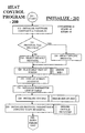
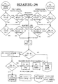
- Figures 9A to 9K illustrate a flow chart of a suitable heat control program 200.
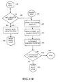
- Figures 11A to 11D illustrate a flow chart of a suitable video processing program 600.
- the heat control program 200 and the video processing program 600 may be implemented using commercially available programming languages such as BASIC or C.
- Figure 10 is a plot of temperature vs. time for the heating ring(s) (and consequently the reaction chamber 30) as they are taken through a denature protocol, a cycling protocol and a superheat protocol.
- Figure 10 assumes there are two heating tiers, but that either they parallel one another or only one is in use until the superheat cycle.
- the heating ring(s) start at a particular temperature at Time T o .
- This temperature may be any value at or below the holding temperature from the end of the last amplification reaction.
- the heating ring(s) are about room temperature at T o .
- the heat control program 200 instructs the PCB 120 to bring the heating ring(s) to a first "set” temperature, in this case the "Denature Temperature", the value of which is selected for denaturing nucleic acid in the sample and/or any probe or primer reagents.
- the Denature Temperature typically ranges from about 80-100°C; the exemplary value is 95°C.
- the temperature gradually rises or "ramps" up to the set temperature during the period from T o to T 1 .
- the program 200 senses when the heating ring(s) have reached the selected set temperature and holds this temperature for the predetermined period from T 1 to T 2 (the "Denature Time") in order to denature the sample DNA and any reagent probes or primers.
- the program resets the set temperature to the "Low Cycling Temperature” and the heating ring(s) "ramp” down to this new set temperature during the period from T 2 to T 3 , which is maintained for the "Low Cycling Time”.
- the ramp down times e.g. T 2 to T 3 and T 6 to T 7
- the values for these parameters are selected to provide the temperature and time for reannealing primers or probes to the suspected target or amplicons made from target.
- Annealing temperatures depend on probe length and the content of guanosine and cytosine residues, as is known in the art, and are typically set several degrees below the predicted T m for the probes or primers.
- Low Cycling Temperatures can range from about 45-70 °C; the exemplary value being set at 60 °C. This period is shown in Figure 10 from T 3 to T 4 .
- the program resets the set temperature and ramps up to the "High Cycling Temperature” which is held for the "High Cycling Time” as shown in Figure 10 from T 4 to T 5 and T 5 to T 6 .
- Values for the High Cycling Temperature and High Cycling Time are selected to again denature the probes or primers from the target or amplicons.
- the High Cycling Temperature is slightly lower than the sample Denature Temperature, but it must be greater than the Tm of the amplicons. Values ranging from about 70-95°C are common; the exemplary value is 80°C.
- the program After the High Cycle Time has expired, the program resets the set temperature to the "Low Cycling Temperature", the heating ring(s) "ramp” down to T 7 and the process repeats. Each cycle consists of a high and a low temperature, as shown in Figure 10. "Total Number of Cycles” is the parameter whose value controls the number of cycles. The number of cycles will vary greatly depending on the assay being performed. For both PCR and LCR, it is not uncommon to have between 10 and 70 cycles, generally between 25 and 50.
- the program moves into the Superheat aspect to transfer the reaction sample 38 from the reaction chamber 30 to the detection chamber 32 as described above in connection with Figures 5A -5E.
- this is generally accomplished by superheating the lower tier first and the upper tier second for reasons described above.
- the lower tier is also superheated to a higher temperature than the upper tier as shown in Figure 10.
- the Lower Block Superheat Temperature and the Upper Block Superheat Temperature are the parameters that hold the values for these superheat stages. As mentioned earlier, these values are selected to expand a propellant, thereby forcing the reaction sample into the detection chamber.
- This temperature is generally as high or higher than the denature temperature, but it need not be since the propellant can be shielded from the denaturing temperatures by placing it low in the reaction chamber (i.e. within the lower tier) and not tracking the two tiers.
- an aqueous reaction sample may serve as propellant and the superheat temperatures will generally range from about 90-120°C.
- the "Lead Time For Superheat” is an optional time period during which the lower heating ring 92 is brought to its superheat temperature before the upper heating ring 90 is brought to its superheat temperature.
- the Lead Time For Superheat is shown in Figure 10 from T s to T u. An exemplary value is given above as 15 seconds.
- the Lead Time (T s to T u ) may be greater than, equal to or less than the ramp time (T s to T p ); in other words, the relative positions of T u and T p may be reversed from that depicted.
- the "Overall Superheat Time” holds the time value for the superheat stage, commencing when the upper tier (or the single tier if only one is used) reaches its set temperature (e.g. the Upper Block Superheat Temperature). This time is shown in Figure 10 from T e to T r and needs only be sufficiently long to transfer an adequate volume of the reaction sample to the detection chamber. This of course is dependent on the sample volume and the detection means, but is easily determinable by simple experiment. An exemplary value is 30 seconds. It should be noted, however, that all exemplary times and time ranges are subject to the specific embodiments utilized herein and that the use of other ranges is easily within the ability of those skilled in the art.
- the "Tracking" parameter determines in the case of a two tier heating element whether both the upper and the lower heating rings 90, 92 participate in the denature protocol and the cycling protocols. If the Tracking parameter is on, both heating rings 90, 92 participate in the denature protocol and the cycling protocols. If the Tracking parameter is off, only one of the heating rings 90, 92 participates in the denature protocol and the cycling protocols.
- the "Shutoff Temperature At The End Of The Reaction” is the set temperature at which the program 200 turns off the fan motor that cools the heating rings 90, 92 at the end of the testing protocol, represented in Figure 10 by T h .
- the "Image Delay Time” merely signals the computer to wait a specified time before beginning the detection procedures. This time should be sufficient to permit the signal in the detection chamber to fully develop, and may range from about 1-10 minutes or more, depending on the type of signal and detection means employed.
- Figure 10 also shows the Program States for the Denature and Cycle/Superheat routines. These are described below in connection with the software.
- Block 220 provides help information to assist operators in deciding what steps to take to continue the program 200.
- the screen headings at block 222 also provide prompts regarding keystroke entries to obtain a desired result.
- the program 200 initializes a thermistor look-up table at block 224. Although the resistance of the thermistors 122, 123 varies with temperature, these temperature changes are not linear. Thus, a look-up table is provided so that the program 200 does not have to recalculate the temperature every time a reading is delivered from either of the thermistors 122, 123.
- the I/O card 118 is initialized at block 226. This sets the various values that will be used on the I/O card 118 such as the gain settings on the pre-amp stages or the use of unipolar (0 volts to 10 volts) or bipolar (-5 volts to +5 volts) signal ranges.
- the protocol parameters are initialized and the I/O card 118 is prepared to convert temperatures to digital. Block 230 moves the program 200 to the Edit section 204.
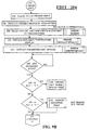
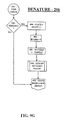
- the Edit section 204 of the program 200 is shown in Figures 9B, 9C and 9D.
- the Edit section 204 allows the operator to change some or all of the protocol parameters chosen at blocks 216 and 218 of the Initialize section 202.
- the program 200 provides a continuous display of the current temperature of the heating rings 90, 92. This is accomplished at blocks 240 and 242 by reading the analog inputs from the upper and lower heating rings 90, 92, converting these inputs into temperature values at the thermistor look-up table, and displaying the temperature on the monitor 113.
- the program 200 also displays on the monitor 113 the parameter edit command instructions which provide prompts to the operator for editing the protocol parameters.
- the Edit section 204 looks for a keyboard input at block 246 until one is received.
- the operator may now edit protocol parameters by hitting any of the keys shown in blocks 250, 256, 260, 264, 270, 280, 284, 288, 294 and 298.
- the "U” key, shown at block 250 takes the program 200 to block 251 which allows the operator to reset the high cycling temperature and the time duration of the high cycling temperature.
- the "L” key, shown at block 256 takes the program 200 to block 258 which allows the operator to reset the low cycling temperature and the time duration of the low cycling temperature.
- the "C” key, shown at block 260 takes the program 200 to block 262 which allows the operator to set the maximum number of cycles.
- the "W” key takes the program 200 to blocks 266 and 268 which allow the operator to save the edited parameter protocols in a file in the computer's memory.
- the "F” key takes the program 200 to block 272 which allows the operator to turn on the fan 94 and thereby bring down the temperature of the heating rings 90, 92, if desired.
- the "D” key takes the program 200 to block 282 which allows the operator to edit the denature temperature and the time duration of the denature protocol.
- the "H” key shown at block 284, takes the program 200 to block 286 which allows the operator to edit the superheat parameters.
- the superheat parameters include the superheat temperature for the lower heating ring, the lag-time for superheating the upper heating ring, the superheat temperature of the upper heating ring, and the overall time period for the superheating.
- the "T” key shown at block 288, takes the program 200 to block 290 which allows the operator to edit the tracking parameter. After the program 200 polls the T key at block 288, the timers are set at block 292 in anticipation of starting the Denature section 206.
- the "E” key shown at block 294, takes the program 200 to block 296 which exits the program 200.
- the "S” key shown at block 298, sets the "state,” “cycle number”, “RTime” and “key” all to 0 (block 300), and moves the program 200 to the Denature section 206 from block 304. If the S key is not pressed, the program 200 returns to the beginning of the Edit section 204.
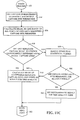
- the Denature section 206 begins at block 310 and displays the current protocol parameters at block 312. Block 314 clears the keyboard inputs, and block 316 examines the value that was entered for the denature temperature (TEMP.DEN). If the denature temperature has been set to 0, the program 200 skips the denature protocol and sets the "cyclenum" flag to 1 and the state flag to 0 (block 318) before moving into the Cycle/Superheat routine via block 320. By entering the Cycle/Superheat section 208 via block 420, the program starts the sample out at the High Cycling Temperature by setting SETTEMP equal to TEMPHI at block 422 and by entering the Cycle/Superheat routine 208 with the state flag at 0.
- the Denature temperature is set to a value greater than zero (95°C), so the program 200 initializes the Denature temperature and Denature time at block 322 which includes several subroutines for getting the tracking information, setting the Denature temperature and turning the fan 94 off.
- “Setting” a temperature or a time involves creating a variable such as SETTEMP, SETTEMP0 or SETTEMP1 for temperature, and RTIME for time, and assigning a value to said variable the value being selected from one of the parameters described above: namely, TEMP.DEN, TEMPLO, TEMPHI, TEMPSUPER and TEMPSUPER2 for temperature variables and TIME.DEN, TIMELO, TIMEHI, TIMELEAD and TIMESUPER for the time variable.
- the SETTEMP variable assumes the value stored in the protocol for the Denature Temperature.
- Blocks 311, 324 and 326 show that Denature section 206 continuously polls the keyboard 114 for parameter edit inputs from the operator. If a keyboard input is received, the program 200 moves to the Edit section 204, and the operator can then edit any of the current protocol parameters. The program 200 updates the temperature display at blocks 328 and 330.
- the program 200 branches to poll either temperature or time depending on the value of the program state flag, the key flag and the RTime. Since RTime (as well as other variables) was set to 0 at block 300, the program polls temperature on this first pass through the loop and moves on to block 336.
- TRACK off
- the TRACK variable is unnecessary and only one block is examined.
- the following description assumes a two block system wherein the upper block only is used for denaturing and cycling, it being understood that this is just one embodiment.
- the program state flag can have four values from 0 to 3.
- the program 200 has signaled the PCB 120 to take the heating rings to the denature temperature, and the program 200 (at block 332) polls the A/D converters 142, 144 on the I/O card 118 to determine when the upper heating ring has reached the denature temperature (see block 346). If the upper heating ring has not yet reached the denature temperature, the program 200 moves through blocks 350, 372 and 382, and returns to the main denature loop near the beginning at block 311. From there, the program returns to block 346 and again inquires as to whether the upper heating ring has reached the denature temperature (95°C).
- the program 200 continues this loop until the upper heating ring 90 has reached the denature temperature.
- the answer at block 346 is now yes, and the program 200 sets the key flag to 1 at block 348.
- the key flag is set to 1 at block 348, and the program state flag is incremented to 1 at block 374.
- the variable RTime is set to assume the value of parameter TIME.DEN (Denature Time) at block 378, the timer is started at block 380 and the program returns to the main denature loop (blocks 382 and 311).
- RTime now holds a value (120 seconds in the example)
- the program branches at block 332 to the "Timecheck" subroutine at block 396 and inquires if RTime has timed out.
- RTime "times out” when the period set for the particular activity (in this case, the 120 sec. Denature Time) expires. If the answer to this inquiry is no, the program loops back through the beginning of the Denature section 206 and returns via blocks 332 and 334 to the timeout inquiry at block 398. If the answer to the timeout inquiry is yes, then the program 200 increments the program state flag (to 2 now) at block 400 and resets Key and RTime to 0 at block 402. The program 200 then resets the SETTEMP variable to equal the parameter value TEMPLO (block 406) and turns on the fan (block 408) to ramp the heating block 90 down to the Low Cycling Temperature.
- the program 200 Upon return to the Main Denature Loop (block 311) with the program state flag at 2 and RTime reset to 0, the program 200 branches through blocks 336, 340, 342 and 344 to block 350, and again polls the upper heating block 90 at block 352 to determine if it has reached the SETTEMP (now the Low Cycling temperature). If the upper heating block 90 has not yet reached its set temperature (60°C in the example), the program 200 loops back to block 352 through blocks 372, 382, 311, 332, 336, 340, 342, 344 and 350. When the Low Cycling SETTEMP is reached, the program increments the Key to 1 and the state flag to 3 (blocks 348 and 374) and turns the fan off (block 390).
- the Cycle/Superheat section 208 begins at block 421, the SETTEMP having already been initialized. As with the Denature section 206, the Cycle/Superheat section 208 also continuously polls the keyboard 114 for parameter edits inputs, and returns the program 200 to the Edit section 204 whenever it receives the appropriate input from the keyboard 114. The current temperature of each of the heating blocks 90, 92 is fed to the I/O card 118 and displayed at blocks 428 and 430.
- the program 200 asks whether it should check time or temperature depending on the value of RTime.
- the RTime is 0 here (having been reset last at block 402), so the program branches to block 436 to check the temperature of the heating blocks. Tracking is off, so the inquiry at block 436 leads to the state inquiry at block 438 and then to the state inquiry at block 462.
- the program state flag can have eleven values from 0 to 10, but was set to 2 leaving the Denature Section (block 392), thus the program asks at block 464 whether the upper heating block has reached the Low Cycling temperature of 60°C.
- the program state flag is incremented (to 3) at block 512.
- Block 514 is answered no and block 518 is answered yes, causing the program 200 to reset RTime to assume the value of TIMELO (the Low Cycling Time of 60 seconds in our example) at block 520.
- the program also turns the fan off at block 522 and starts the timer at block 536 before moving back to the beginning of the Cycle/Superheat section 208 at block 421.
- the program 200 moves through the beginning of the Cycle/Superheat section to block 432. Because the RTime now holds a value (60 sec), the program branches from block 432 to the Checktime subroutine beginning at block 550. If the RTime has not expired, the program returns to the main loop until the 60 seconds in the RTime has timed out. When the RTime has timed out, the answer to the inquiry at block 552 is yes, and thus the program 200 increments the state flag to 4 at block 555 and resets RTime and Key to 0 before moving on to block 562 via block 556.
- the program queries the "cyclenum" flag. If the cyclenum flag has not exceeded the maximum number of cycles, stored as protocol parameter CYCLEMAX, the program 200 resets the program state flag to 0 and sets the variable SETTEMP to the value of the High Cycle Temperature parameter and turns the heating element(s) on for beginning the next cycle (blocks 568 and 586) and then returns to the main loop at block 421.
- the program state flag is incremented (to 1) at block 512 and block 514 is answered yes, causing the program 200 to reset RTime to assume the value of TIMEHI (the High Cycling Time of 60 seconds in our example) at block 516.
- the program also starts the timer at block 536 before moving back to the beginning of the Cycle/Superheat section 208 at block 421.
- the program 200 moves through the beginning of the Cycle/Superheat section 208 to block 432. Because the RTime now holds a value (60 sec), the program branches from block 432 to the Checktime subroutine beginning at block 550. If the RTime has not expired, the program returns to the main loop (block 554) until the 60 seconds in the RTime has timed out. When the RTime has timed out, the answer to the inquiry at block 552 becomes yes, and thus the program 200 increments the state flag to 2 at block 555 and resets RTime and Key to 0 before moving on to block 556.
- the answer is yes causing the program to reset the variable SETTEMP to the value of the Low Cycle Temperature parameter (TEMPLO) at block 558 and at block 560 turns on the fan for cooling the heating block(s) before returning to the main loop at block 421.
- TMPLO Low Cycle Temperature parameter
- the program reached block 432 and decides to poll the temperature (block 464) since RTime is 0. This continues until the desired (TEMPLO) temperature is reached, upon which key is set to 1 at block 466. This sends the program back to the "Change State” subroutine (block 510) where the state flag is incremented (to 3) and RTime is reset to TIMELO for holding the heating block(s) at TEMPLO for the desired time period. This causes the program to branch at block 432 to the Checktime subroutine (block 550) to poll the timer. As before, when RTime times out, the state flag is incremented at block 555 (to 4), RTime and Key are reset to 0 and the cyclenum flag is again evaluated. The program 2.00 continues to execute cycles as described above using program states 0, 1, 2 and 3 until CYCLEMAX is reached (e.g. until the cyclenum flag is incremented to 9 at block 564).
- the program 200 examines the value of TEMPSUPER at block 570. If it is 0, the superheat portion is skipped by setting the program state flag to 8 at block 574.
- the value of TEMPSUPER is 110°C, which starts the lower ring superheat process by setting the variable SETTEMP1 equal to 110°C at block 572 before returning the main loop at 421.
- SETTEMP1 is a variable that holds a value for the set temperature of the lower block only, whereas SETTEMP was applied to the upper block or to both blocks if Tracking was on.
- the program In the main loop, the program once again polls temperature at block 432 since RTime is 0, and skips through inquiries at 438 and 462 to reach the inquiry at 478, which is answered yes.
- the program assumes here that if Tracking was off, the lower heating block is at a lower temperature than the upper block and state 4 is maintained until the lower block comes up to the temperature of the upper block.
- the key flag is set to 1 which causes a state change via blocks 496, 500 and 510. This increments the state flag (to 5) and loads the TIMELEAD value into the variable RTime at block 526 and restarts the timer at block 536 before returning to the main loop.
- the TIMELEAD value is the time period by which the superheat of the lower heating block 92 leads the superheat of the upper heating block 90. This is represented by the exemplary 15 seconds and in Figure 10 by the time period between T s and T u .
- SETTEMP0 is a variable that holds a value for the set temperature of the upper block only, as distinct from the lower block or both blocks (as when Tracking is on).
- the program branches to poll temperatures at block 432 and reaches block 484 and 486 to examine whether the upper block has reached its set temperature (TEMPSUPER2).
- the key flag is changed to 1 at block 488 to move the program 200 to the Change State subroutine at block 510.
- TIMESUPER was 30 seconds and represents the period of time during which the upper block is maintained at the superheat temperature.
- the program 200 increments the state flag (to 8), resets the key flag and RTime and moves to block 580 where the program turns off the temperature outputs to the upper and lower heating rings at block 582.
- the program at block 584 turns the fan on and resets the SETTEMP variables for both heating blocks to the value of SHUTOFF. This value, 50°C in the example, is selected so that the fan will not run constantly trying to cool the heating blocks below ambient temperature.
- the program Upon return to the main loop with the program state at 8 and RTime reset to 0, the program branches at block 432 to poll temperatures.
- the answer is yes so at block 492 the program polls the temperature of the upper block to determine if it has cooled to the set temperature of 50°C.
- the key flag is set to 1 at block 494, causing a state change via blocks 496, 500, 510 and 512 to state 9.
- the program branches to turn the fan off (block 534) and to load the value of TIMEIMAGE into the variable RTime (block 535) before starting the timer (block 536) and returning to the main loop.
- the TIMEIMAGE parameter is selected to allow the unit to compete its development of signal before starting the detection process.
- block 432 branches to the Check Time subroutine and, upon timeout, increments the state flag (to 10) causing the program via blocks 581 and 583 to begin the detection procedures, described below in connection with Figures 11A to 11D.
- the detection system 22 utilizes a video processing program such as the Detection Program 600 illustrated in Figures 11A-11D.
- a video processing program such as the Detection Program 600 illustrated in Figures 11A-11D.
- the detection program uses digital video analysis techniques to analyze the video image of the detection means 60 (e.g. strip 61) generated by the camera 100 of the detection system 22.
- the video processing program uses the digital data acquired from replicate capture sites to improve the accuracy and reliability of the overall amplification reaction as described below.
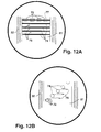
- Each detection means 60 includes at least a read zone 68 as shown in Figures 2A, 2G and 5A-5D.
- the read zones 68 of the devices of Figures 2A and 5 are shown in enlarged view in Figures 12A and 12B.
- the detection means 60 preferably also includes a reference bar and/or a control zone 70.
- each read zone 68 preferably includes multiple capture sites 74 for the purpose of multiplexing the assay.
- Multiplexing refers to performing an assay for more than one analyte at the same time; for example, testing for both Chlamydial organisms and gonococcal organisms, or testing for genetic mutations at multiple sites in a gene or even in multiple genes. Multiplexing can also refer to the simultaneous assay of one analyte along with a positive and/or negative control reagent.
- These multiple capture sites 74 are depicted as continuous bands or lines in Figures 2A and 12A, and as a diagonal array of "spots" in Figure 5 and 12B. They were also described earlier as discontinuous bands or line as seen in Figure 2G
- each distinct capture site 74 must be distinguished from what will be described below as replicate sites 72 or replicate zones.
- the area of each distinct capture site 74 is large enough to support several "reading windows" which are referred to herein as replicate sites or replicate zones. These are depicted in Figure 12A as the boxed areas on the top capture site 74, and as multiple scan lines on the spot 74 in Figure 12B.
- the discontinuous bands create natural replicate zones, while with continuous bands the replicate zones are created arbitrarily (see boxes 72 in Figure 12A) by the reading software.
- each replicate site or zone of a capture site 74 contains additional data for the same analyte, as if "replicate” assays were being performed for that analyte. Having a plurality of replicate sites permits discarding of statistical "outliers" and increases the confidence level that the image of the capture site is correctly and faithfully evaluated.
- the computer 26 and the video processing program detect the presence of amplified target nucleic acid immobilized on the support 61.
- the camera 100 detects an image of the support 61, usually in accord with one of the configurations illustrated in Figure 8.
- the camera 100 then outputs a video signal to the frame grabber card 116 of the computer 26.
- the frame grabber card 116 digitizes a video frame and stores the digital values in RAM 124.
- the digital values are accessible to the computer 26 and may be manipulated by the video processing program 600.
- the computer 26 uses an 8-bit gray scale having a resolution of 512 x 484 pixels.
- a numerical value is assigned to each pixel such that a zero (0) represents a black image, and two hundred and fifty-five (255) represents a white image.
- the values between 0 and 255 each represent a particular shade of gray.
- the digitized representation of the video signal may be shown on the computer monitor 113 for viewing by an operator.
- the video processing program 600 is illustrated by the flow chart shown in Figures 11A to 11D.
- the flow chart uses conventional symbols to represent the major functions performed by the video processing program 600.
- the video processing program 600 has two major sections or loops. The first section is the “Read” section which begins in block 606, and the second section is the “Assay” section which begins in block 634 and is a subroutine of the Read section 606.
- the Read section is executed once for each reaction/detection unit 20, and the Assay section is executed once for each capture site 74 imaged from the detection means 60 of each unit 20.
- the program 600 starts in block 602 and initializes a position counter in block 604.
- the position counter keeps track of the number of reaction and detection units in a particular batch.
- the heating rings 90, 92 include forty wells 97 for holding reaction/detection units 20.
- Block 608 advances the motor 108 or 109 to the next sample read position.
- the motor 108 would rotate the mirror as well in order to present successive images of each detection means 60 to the camera 100.
- the reaction/detection units 20 preferably are provided with a bar code (not shown) which identifies the reaction sample 38 and the unit 20, and contains information about the assay to be performed for this reaction/detection unit.
- the bar code preferably also provides the computer 26 with information about the configuration of the detection means 60, such as information about the presence, location of and geometry (e.g. bands or spots) of control zones 70, capture sites 74, and replicate zones 72.
- there are a limited number of such configurations and configuration information is stored in the computer's memory, to be retrieved by the computer upon receipt of a bar code signal that is associated with a particular configuration.
- a single reference bar can provide a frame of reference for image analysis.
- the cycler 16 and/or the computer 26 are then provided with a code reader (not shown) for reading the bar code.
- the program 600 reads the bar code information in block 610 and determines in block 612 whether the bar code was read successfully. If the read was unsuccessful, the program 600 indicates in block 614 that no bar code was read for this unit. In systems where bar code information is needed to locate the position and number of capture sites, the computer will not know how to process the particular unit 20 if the barcode is not successfully read and no result can be reported so the program 600 moves to block 616 which sends the program 600 to the sample end routine at block 678. If the read was successful, the program 600 moves to block 618 in which the zone configuration information is processed in preparation for obtaining and examining the digitized image.
- the control zone is typically a prescribed zone that is ordinarily positive for any reaction sample.
- the control zone generally serves two functions. First, it indicates to the operator that the amplification reaction and transfer of the sample to the detection chamber proceeded properly. Second, it provides a reference point for determining the location of the capture sites as defined by the bar coded configuration information.
- the program inquires whether the control zone was found. If the answer to the inquiry at block 624 is no, the program indicates an error code for the current sample and proceeds to block 616 which sends the program 600 to the sample end routine at block 678. If the answer to the inquiry at block 624 is yes, the program 600 proceeds to block 628 which sends the program 600 to the Assay Read routine at block 630.
- the Assay Read routine moves to block 632 and, using the zone configuration information provided by the unit bar code or by other input, selects the first analyte zone for processing.
- Each analyte zone is divided into a plurality of scan-lines having a plurality of pixels in each scan-line.
- Each pixel was assigned a grayscale numerical value during the digitizing procedure in block 620.
- the program 600 examines the scan-lines in the current analyte zone and calculates the pixel mean, standard deviation (SD) and range values for each scan-line in the current analyte zone.
- SD standard deviation
- the program 600 then moves to block 638 and asks whether any of the scan-lines in the current analyte zone are statistically different from other scan-lines in the current analyte zone. If the answer to the inquiry in block 638 is no, the program moves to block 640 and reports a negative result for the current analyte zone. The program 600 then moves from block 640 to block 642 which sends the program 600 to the next zone routine at block 670. If the answer to the inquiry in block 638 is yes, the program has detected a positive result for the current analyte zone and moves to block 644.
- Block 644 begins a background normalization procedure, where the program classifies each scan-line of the current analyte zone as containing some signal or only background. Using scan-lines classified as background only, the program 600 then establishes a background gradient for the current analyte zone in block 646, and uses this gradient to account for variance in lighting and position. Background gradients may be established in a variety of known ways such as by derivative and row/column analysis as is known in the art. In block 648, the program performs background adjustments or normalizations on the signal scan-lines using the background gradient information. Background normalization is traditionally used to establish a signal baseline and improve data interpretation, and may also be accomplished in a variety of known ways such as by subtraction or horizontal/vertical mean subtraction. The program then moves from block 648 to block 650 which transfers the program 600 to block 652.
- the image processing subroutine begins at block 652.
- the program uses contour enhancement to identify the perimeter of signal area 77 in a successful replicate site 72.
- Contour enhancement is a known digital image processing technique for feature extraction and is applied here to determine the contours or boundaries of the signal area for each replicate site.
- the program calculates the mean, standard deviation and range values for all pixels within the perimeter of each replicate site signal area. The analysis is now focused on the signal areas of the replicate sites.
- the program identifies any anomalous results by asking whether any of the signal area statistics in one replicate site are significantly different from the signal area statistics from other replicate sites 72. If the answer to this inquiry is no, all of the replicate sites 72 are judged to be the same, and the program 600 then calculates at block 660 the mean pixel value of the signal areas within all the replicate sites and stores this value as a result for the current analyte zone. From block 660, the program moves to block 662 which transfers the program to the next zone routine at block 670.
- the program 600 moves to block 664 which removes aberrant results which are referred to as statistical "outliers" or "fliers".
- Aberrant results can be defined statistically in a number of ways, including results falling too far from the mean, "too far” being defined in terms of the number of standard deviations, or in terms of the statistical significance within preset confidence limits.
- the program determines whether there are enough acceptable sites remaining after discarding the aberrant or anomalous sites to obtain a reliable test result. Any of several criteria may be used to make the determination set forth in block 666. For example, the program may require a fixed percentage (e.g. at least 50%) of the identified replicate sites to be acceptable.
- the program proceeds to block 660 to calculate the mean pixel value of the signal areas within the acceptable replicate sites and stores this value as a result for the current analyte zone. If the number of acceptable capture sites does not exceed the established minimum, the program proceeds to block 668 which sets the indeterminate result flag for the current analyte zone. In other words, the program could not find sufficient reliable data in the scanned image to reach a firm conclusion regarding the assay. The program then moves from block 668 to block 662 which takes the program to the next zone subroutine at block 670.
- the program then moves to block 672 and asks whether the current zone is the last zone. If the answer to the inquiry in block 672 is no, the program selects the next analyte zone in block 674 and then moves to block 676 which returns the program to the assay loop at block 634. If the answer to the inquiry in block 672 is yes, the detection for the current reaction/detection unit 20 is complete, and the program moves into the sample end subroutine which begins at block 678.
- the program 600 stores all of the sample results and then displays and/or prints all sample results in block 682.
- the program can be configured to store all the data and print it at the end of a run.
- the position counter is then incremented in block 684, and the program asks in block 686 whether the last position has been completed. If the answer to the inquiry in block 686 is no, the program moves to block 690 which returns the program to the read loop at block 606. If the answer to the inquiry in block 686 is yes, the program ends at block 688.
- video imaging aspects of this invention are not limited to the preferred two tier cycling element and, in fact, are not limited to nucleic acid analysis at al. Rather, the video imaging aspects may be utilized on any form of assay, including for example immunoassay, where a signal can be generated such that it can be distinguished from the background using a camera means, and preferably some form of electromagnetic illumination.
- the amplification reaction sample generally comprises target nucleic acid, at least one enzymatic agent that induces amplification, and a buffer.
- Enzymatic agents contemplated by the invention include, but are not limited to, ligases and polymerases, and combinations thereof.
- the reaction sample may also include primers or probes, which are described further below. Preferably, primers or probes are added in molar excess of the amount of target nucleic acid in the reaction sample.
- reaction sample will generally also include nucleotide triphosphates, dATP, dCTP, dGTP, and dTTP.
- LCR reaction samples usually include NAD. The amounts of all such reagents in the reaction sample may be determined empirically by those persons skilled in the art. Examples of reaction samples for particular amplification reactions are described further in Examples 4, 9, and 11 of this disclosure.
- the nucleic acid of interest to be amplified may comprise deoxyribonucleic acid (DNA) or ribonucleic acid (RNA), and may be natural or synthetic analogues, fragments, and/or derivatives thereof.
- the target nucleic acid is preferably a naturally-occurring viral nucleic acid or DNA of prokaryotic or eukaryotic origin.
- primer and probe as used in the present application are intended to refer generally to an oligonucleotide which is capable of sufficiently hybridizing with the target nucleic acid.
- primer is typically used in connection with PCR
- probe is typically used in connection with LCR.
- primer/probe will be used in the present application where general discussions can apply to both primer and probe sequences.
- the primer/probe is preferably selected to be complementary to various portions of the target nucleic acid.
- the length of the primer/probe will depend on various factors, including but not limited to, amplification reaction temperature, source of the primer/probe, complexity of the target nucleic acid, and the type of amplification reaction.
- each primer/probe is sufficiently long to have a desired specificity and avoid hybridization with random sequences that may be present in the reaction sample. More preferably, each primer/probe comprises about 15 to about 100 bases, and even more preferably, about 15 to about 40 bases.
- the primer/probe may be chemically synthesized using methods known in the art.
- the primer/probe is synthesized using nucleotide phosphoramidite chemistry techniques known in the art and/or instruments commercially available from Applied Biosystems, Inc. (Foster City, CA), DuPont (Wilmington, DE) or Milligen (Bedford, MA).
- Pimer/probes may be directly linked to detectable label which does not interfere with hybridization.
- a specific binding pair member is attached to at least one primer/probe employed in the amplification reaction.
- a specific binding pair member is attached to each primer in a primer pair, or to at least two probes in a set of probes employed in the amplification reaction. More preferably, the specific binding pair members thus attached to the primers in the primer pair or to the at least two probes in the set of probes are two different specific binding pair members.
- a first specific binding pair member attached to a primer pair or probe set can be used to couple amplified target with a reporter molecule conjugated to a detectable label.
- the second specific binding pair member can then be used to bind the labeled amplified target to a capture molecule immobilized on the support 61.
- the two specific binding pair members do not cross react with each other and do not cross react with the labeled reporter molecules or the capture molecules immobilized on the support 61.
- the specific binding pair member comprises an antigen, hapten, chemical compound, or polynucleotide capable of being bound by another molecule such as an antibody or complementary polynucleotide sequence.
- the specific binding pair member may also be a magnetic particle.
- Specific binding pair members contemplated by the present invention include, but are not limited to, biotin, T3, oligonucleotides, polynucleotides, and drug compounds such as theophylline, digoxin, and salicylate. Such specific binding pair members are known in the art and are commercially available.
- the specific binding pair member may be attached to the primer/probe through covalent bonding or standard ⁇ -cyanoethyl-phosphoramidite chemistry techniques. Enzo Biochemical (New York) and Clontech (Palo Alto, CA) have also described and commercialized primer/probe labeling techniques. The methods employed will vary depending, for instance, on the type of specific binding pair member and the position of the binding pair member on the primer/probe sequence.
- the binding pair member should, however, be attached by thermostable means to survive any temperature cycling employed in the amplification reaction.
- the reaction sample 38 is placed in the reaction chamber 30. Because the quantity of reaction sample is typically small, it may be preferable to place the sample 38 in the reaction chamber 30 using a microsyringe pipette (not shown), or to briefly centrifuge the chamber to force the sample 38 to the bottom of the chamber.
- the reaction chamber 30 and detection chamber 32 are then engaged to form a sealed unit 20, and the unit 20 is placed in a thermal cycling device 16, preferably, a thermal cycling device 16 as shown in Figures 6-8 and described herein.
- the reaction sample 38 is then exposed to temperature conditions sufficient to amplify target nucleic acid present in the reaction sample. For some amplification reactions, such as PCR and LCR, the reaction sample will be exposed to thermal cycling.
- amplification reactions may employ isothermal conditions.
- thermal cycling conditions the reaction samples are typically exposed to a range of temperatures for set periods of time.
- LCR there is usually temperature cycling at two different temperatures.
- the reaction sample is cycled at 85°C and 55°C.
- suitable temperatures, cycling times, and the number of cycles needed to complete the amplification reaction Under appropriate temperature conditions, and in the presence of target nucleic acid in the reaction sample, the primers or probes will hybridize to the target nucleic acid as the amplification reaction proceeds.
- the reaction sample is tansferred from the reaction chamber 30 to the detection chamber 32 so that the reaction sample 38 comes into contact with the support 61 ( Figures 5A to 5E).
- the unit 20 remains sealed.
- the transfer of sample may occur by various means such as by creation of a vapor phase or expansion of fluid or propellant caused by increased temperature.
- transfer of the reaction sample 38 to the detection chamber 32 occurs by expansion of a propellant 40 at the bottom end of the reaction chamber 30.
- the expansion of the propellant 40 is caused by the computer 26 raising the temperature of the lower heating element 18 (or only heating element 17) above the propellant's threshold temperature. More particularly, the computer 26 directs the heating element 17 or 18 to deliver heat to the second longitudinal segment 35 of the reaction chamber 30 so that the propellant 40 is exposed to a temperature above the propellant's threshold temperature.
- the element is super-heated to a temperature above 95°C, usually at or above 100°C. The heat thus delivered to the reaction chamber 30 causes the propellant to expand, thereby transferring the reaction sample upward toward the detection chamber 32.
- the temperature needed to expand the propellant 40 will depend on the nature and composition of the propellant 40. It is preferred that the propellant 40 has a threshold temperature above the amplification reaction temperature(s) so that the propellant 40 does not expand during the course of the amplification reaction.
- one region 66 of the support 61 comprises multiple conjugate molecules capable of binding to a first specific binding pair member attached to the amplified target in the reaction sample.
- the conjugate molecules are deposited on the support 61 using methods known to persons skilled in the art.
- the conjugate molecules can be deposited on the support 61 by spotting and drying.
- the conjugate molecules are dried on the support 61 in the presence of meta-soluble proteins, such as casein, to aid in the transport and resolubilization of the conjugate molecules.
- the conjugate molecules can also be deposited on the support by methods described in U.S. Patent No. 5,120,643.
- conjugate molecules in the region 66 are not immobilized on the support but rather are capable of resolubilizing in the presence of reaction sample and/or aqueous solvent and move along the support by capillary movement.
- conjugate components capable of binding to the specific binding pair members described above include, but are not limited to, antibiotin antibodies, anti-theophylline antibodies, avidin, carbohydrates, lectins, complementary oligonucleotide or polynucleotide sequences, streptavidin, and protein A.
- label refers to a molecule which can be used to produce a detectable signal. The signal should be able to be detected visually, optically or upon excitation by an external light source. Suitable labels are known in the art and include latex, colored latex particles, and colloidal metals such as gold or selenium. Alternatively, the label may be a fluorescent molecule such as fluorescein, rhodamine, acridine orange, and Texas red. Additional labels which may be employed in the invention are described in U.S. Patent No. 4,166,105; U.S. Patent No. 4,452,886; U.S. Patent No.
- the amplified target nucleic acid coupled to specific binding pair members binds to the labeled reporter molecules.
- the reporter molecules on the support are resolubilized and are mobilized with the amplified target nucleic acid in the reaction sample.
- the conjugate need not be present on the strip and is not needed at all if a detectable label is directly linked to the primer/probe.
- the reaction sample By capillary movement, the reaction sample, along with the labeled amplified target, is transported to a second region 68 of the support 61.
- the second region 68 of the support 61 preferably includes a plurality of capture molecules (capture sites 74) capable of binding to a second specific binding pair member attached to the amplified target nucleic acid.
- the capture molecule(s) should be selected so as to be able to capture and immobilize the amplified target by magnetic attraction. All such capture molecules are immobilized on the support 61.
- Methods of immobilizing the capture molecules on the support 61 include adsorption, absorption, and covalent binding, as well as those methods described in U.S. Patent No. 5,120,643.
- the amount of capture molecules immobilized on the support 61 will vary, depending, for instance, on the binding affinity for the specific binding pair member.
- the concentration of capture molecules immobilized on the support 61 is in molar excess of the amplified target.
- the plurality of capture molecules are immobilized on the support 61 at predetermined locations or zones (capture sites 74) on the support 61.
- the capture molecules can be immobilized in any desired geometric form or configuration, such as a diagonal, vertical, or horizontal configuration, or in the form of circles or bars. It is more preferable to spatially separate any such circles or bars so that the results of the amplification reaction can be suitably detected and resolved.
- reaction sample and labeled amplified target nucleic acid in the reaction sample 38 will bind to the immobilized capture molecules (capture sites 74) on the support 61 and will become immobilized at that location.
- Sample components not bearing the capture hapten will be cleared from the second region 68 to any additional zones and/or to the second end 64 of the support 61 by capillary movement of the reaction sample 38.
- the support 61 may also comprise a third region referred to herein as a "control" zone 70.
- the control zone 70 is modified so as to provide a control or reference standard in the detection method.
- the control zone 70 includes some reagent that will capture a detectable label at a predetermined location on the support 61.
- the support 61 can, of course, comprise additional regions or zones for conducting further analysis.
- the support 61 may comprise a reference spot or zone including a detectable dye which, while not reactive with reagents, provides a detectable signal that serves as a frame of reference for automated imaging by the camera.
- the labeled amplified target nucleic acid immobilized on the support 61 produces a visible indicator, and this visible indicator is detected and analyzed by the detection system 22 and computer 26.
- the visible indicator thus produced is an indication of the presence or amount of amplified target nucleic acid in the reaction sample 38. If no amplified target nucleic acid is present in the reaction sample 38, no labeled amplified target will bind to the immobilized capture molecules and no visible indicator will be measured.
- the density or intensity of the indicator on the support 61 can be read optically by any means. As described herein for one embodiment, the signal is reflected onto a video camera lens 102 by a reflecting mirror 106. As the mirror 106 rotates, each of the supports 61 in each of the detection chambers 32 can be read.
- the invention contemplates alternative methods for labeling and immobilizing target nucleic acid.
- the primer/probe may be coupled to a detectable label during manufacture.
- the primer/probe may be coupled during manufacture with a specific binding pair member that allows it to bind to a detectable label that is conjugated to a complementary specific binding pair member.
- the binding of the complementary specific binding pair members can take place either during or after the amplification reaction.
- amplified target nucleic acid in the reaction sample can be coupled to a detectable label prior to being transferred to the detection chamber 32.
- labeled amplified target nucleic acid is detected in the detection chamber 32 by means of microparticle agglutination.
- a pair of primers or a set of probes is coupled during manufacture with the same specific binding pair member.
- Microparticles conjugated to complementary specific binding pair members are then included as part of the detection means 60.
- amplified target present in the reaction sample 38 binds to the coated microparticles.
- the microparticles agglutinate.
- Unamplified probes or primers may bind only one microparticle, and will not be able to initiate agglutination. The agglutination can then be detected and analyzed by the detection system 22 as described above.
- kits for amplifying and detecting nucleic acids comprise multiple disposable reaction chambers 30, multiple disposable detection chambers 32, and engagement means for sealably securing each reaction chamber 30 to a detection chamber 32.
- Each of the disposable detection chambers 32 include a support 61 modified for immobilizing amplified target nucleic acid.
- the kit also comprises one or more containers holding in a suitable buffer reagents for performing amplification reactions. For PCR, such reagents include DNA polymerase, dATP, dCTP, dTTP, dGTP and at least two primers specific for a predetermined target nucleic acid.
- such reagents include DNA ligase, NAD, and at least four probes specific for a predetermined nucleic acid.
- Suitable containers for the reagents include bottles, vials and test tubes.
- the disposable reaction chambers 32 in the kit are pre-packaged with selected reagents and closed with a puncturable seal.
- Oligonucleotide probes were synthesized by phosphoramidite chemistry on an ABI DNA synthesizer and were haptenated with either biotin or dansyl haptens as indicated.
- the sequences (SEQ ID NOS 1, 2, 3 and 4 shown below) were used to amplify a portion of human chromosome 7 coding for the J3.11 polymorphism which is loosely linked to cystic fibrosis. (I. Bartels, et al., Am J. Human Genetics , 38 :280-7 (1986). They align on the target (50-base synthetic target: SEQ ID NO. 5) as shown below:
- reaction sample mixtures contained the following reagent concentrations in a total volume of 100 ⁇ L: 50 mM EPPS, titrated with KOH to achieve pH 7.8; 20 mM K + ; 30 mM MgCl 2 ; 10 ⁇ M NAD, 1.7 ⁇ M dGTP, 9000 units DNA ligase from Thermus thermophilus; 1 unit DNA polymerase from Thermus aquaticus ; 1 ⁇ g herring sperm carrier DNA; 4 x 10 12 copies (6.7 nmole) of each oligonucleotide probe (SEQ ID NOS. 1, 2, 3 and 4); and 10 7 copies target DNA (SEQ ID NO. 5).
- reaction samples were pipetted into reaction chambers of example 4A.
- the reaction chambers were then centrifuged briefly to force the reaction sample to the bottom of the chamber.
- the reaction chambers were screw-threaded to the detection chambers described in Example 3A to form sealed reaction/detection units 20.
- Example 5 The sealed reaction/detection units of Example 5 were inserted into a split ring thermal cycler. (See Example 1A).
- the upper and lower rings were subject to the following protocol of temperature in order to effect the LCR reaction: 40 cycles of 82°C for 5 seconds and 55°C for 60 seconds. Each cycle took approximately 2 minutes to complete, for a total LCR time of about 80 minutes.
- the lower ring was heated to 110°C, and the upper ring was heated to 100°C. These temperatures were held for 25 seconds.
- the sample was transferred from the reaction chamber to the detection chamber, where the reaction sample contacted the first end of the support 61 containing the labeled anti-biotin conjugate.
- the labeled anti-biotin was re-solubilized, and the reaction sample proceeded by chromatography up the nitrocellulose support 61.
- the amplification product was bound at the anti-dansyl capture sites on the support 61 and visible color development was observed.
- the results of six reaction samples are shown in Figure 13. The three samples on the left contained target DNA and dark spots are visible on the detection strip (see arrow). The three samples on the right contained no target DNA and no spots are visible.
- Example 6 The detection chambers of Example 6 were scanned to a TIFF file with a flatbed scanner (ScanJet C, Hewlett-Packard, Palo Alto, CA) using grayscale settings of brightness 140 and contrast 150.
- the TIFF file was imported into ImageTM (available from the National Institutes of Health, Research Services Branch, NIH), and the images of the developed bands analyzed for pixel density. The results are tabulated in Table 1 below, where maximum density and minimum density refer to the gray level of the image in the immediate vicinity of the band.
- a photographic image of the color reaction product described in Example 6 was taken by the CCD camera.
- the presence or absence and amount of color reaction in the specified regions of the support 61 was determined by analysis of gray scale data files generated from the image, using software described earlier in this disclosure.
- the reaction sample of Example 5 is prepared in a microsyringe-barrel reaction vessel, except that 2 ⁇ L of 1-propanol is placed at the bottom end of the reaction chamber, and the reaction sample is placed in the chamber so that the sample and the 1-propanol are separated by about 2.5 ⁇ L air.
- the reaction chamber is then sealably fitted with the detection chamber 32 to form a sealed reaction/detection unit 20 as in Example 5.
- DNA amplification, and the post-heating protocol of Example 6 are executed, except that the upper and lower ring are both heated to 100°C.
- the vaporization of the 1-propanol forces the reaction sample upwards so as to contact the support 61 in the detection chamber.
- the color reaction product on the support strips 61 can then be analyzed by the imaging detection system described in Example 7 or 8.
- Example 5 The reaction sample of Example 5 was prepared except that several glass microbeads (average diameter 0.2 mm) (Homogenizing beads, Virtis Corporation, Gardiner, NY) were added. The steps described in Examples 6 and 7 were then performed. The glass beads act as nuclei for initiation and localization of boiling at the bottom end of the reaction chamber, and the vapor thus generated serves to transfer the reaction sample into the detection chamber. The color reaction product on the support strips 61 were then analyzed by the imaging detection system and procedure described in Example 7.
- glass microbeads average diameter 0.2 mm
- Homogenizing beads Virtis Corporation, Gardiner, NY
- Oligonucleotide probes (SEQ. ID NOS. 6, 7, 8, and 9) which hybridize with the human ⁇ -globin gene (SEQ. ID NO. 10) were synthesized by phosphoramidite chemistry on an ABI DNA synthesizer and were haptenated with biotin or adamantane as shown.
- reaction sample mixtures contained the following final concentrations in a total volume of 100 ⁇ L: 50 mM EPPS pH 7.8, KCl titrated with KOH to achieve pH 7.8 and 20mM K+, 30 mM MgCl2, 10 ⁇ M NAD, 1.7 ⁇ M dGTP, 9000 units DNA ligase (from Thermus thermophilus), 1 unit DNA polymerase (from Thermus aquaticus), and 1 x 10 12 copies (1.7 pmole) of each oligonucleotide (SEQ ID NOS. 6, 7, 8 and 9).
- Targets were 250 ng human placental DNA (about 10 5 copies), which contain SEQ ID NO. 10, or water.
- Reaction mixtures were pipetted into 100 ⁇ L reaction chambers according to example 4B, the bottoms of which had been melted and cooled.
- the reaction chambers were centifuged briefly to force the reaction mixture to the bottom of the tube.
- the tubes were capped with the detection units of Example 3B to form sealed reaction/detection units.
- Example 12 Amplifying DNA and Transferring Reaction Sample From Reaction Chamber To Detection Chamber
- the combined reaction/detection units of example 11 were inserted into the thermal cycler of example 1B and subjected to the following sequence of temperature in order to effect the LCR reaction: 35 cycles of 88°C for 10 seconds and 53°C for 60 seconds. Each cycle took approximately 2 minutes to complete, for a total LCR time of about 80 minutes. Following the completion of the amplification cycles, the ring was heated to 104°C. This temperatures was held for 25 seconds. By virtue of thermal expansion and vaporization of the reaction mixture, the liquid sample was ejected from each reaction element to the affixed detection element, where the amplified sample entered the dried pad containing anti-biotin conjugate.
- the labeled antibody in the pad was solubilized, and the mixture proceeded by chromatography up the nitrocellulose strip.
- the resultant amplification product was retained at the anti-adamantane capture site and visible color development was seen. No color was seen at any other antibody locus.
- the reaction units are shown in figure 14.
- reaction/detection units of examples 11 and 12 are imaged and processed according to the procedures of Examples 7 and 8.
- Support strips 61 were prepared as in Example 3B with a plurality of antibody binding sites, each antibody specific for a different hapten.
- the strips also contain biotin-labeled egg albumin at a specific location on the support.
- the biotin labeled protein serves as a control or reference standard.
- Oligonucleotide probes are synthesized as described in Example 5 or 11, and:
- Support strips 61 are prepared as in Example 11, except that each antibody (or biotin-labeled protein) appears at three or more specific locations on the strip.
- a plurality of specific capture sites 74 or binding areas allows the video processing program 600 to average the signal from similar spots, thus increasing the confidence of the assignment of a particular result. In addition spurious signal may be rejected if similar spots do not exhibit color.
Landscapes
- Chemical & Material Sciences (AREA)
- Health & Medical Sciences (AREA)
- Clinical Laboratory Science (AREA)
- General Health & Medical Sciences (AREA)
- Chemical Kinetics & Catalysis (AREA)
- Biochemistry (AREA)
- Hematology (AREA)
- Life Sciences & Earth Sciences (AREA)
- Analytical Chemistry (AREA)
- Molecular Biology (AREA)
- Measuring Or Testing Involving Enzymes Or Micro-Organisms (AREA)
- Apparatus Associated With Microorganisms And Enzymes (AREA)
- Sampling And Sample Adjustment (AREA)
- Analysing Materials By The Use Of Radiation (AREA)
- Automatic Analysis And Handling Materials Therefor (AREA)
- Devices For Use In Laboratory Experiments (AREA)
Claims (9)
- Procédé pour transférer un échantillon de fluide contenant un acide nucléique entre une chambre de réaction et une chambre de détection à l'intérieur d'un dispositif, comprenant les étapes consistant à :a) disposer d'un dispositif ayant une chambre de sollicitation aux chocs thermiques allongée et une chambre de détection connectées par des moyens de communication de fluide entre les chambres de sollicitation aux chocs thermiques et de détection, et ayant un échantillon réactionnel disposé dans ladite chambre de sollicitation aux chocs thermiques, dans lequel soit ledit échantillon sert d'agent de propulsion, soit un agent de propulsion est également disposé dans ladite chambre de sollicitation aux chocs thermiques de telle sorte que l'agent de propulsion et l'échantillon soient mélangés entre eux, ou que l'échantillon soit situé entre l'agent de propulsion et les moyens de communication de fluide, et en outre dans lequel ledit agent de propulsion ou ledit échantillon servant d'agent de propulsion peut être dilaté ; etb) déclencher la dilatation de l'agent de propulsion ou dudit échantillon servant d'agent de propulsion pour qu'il occupe un plus grand volume, de façon à forcer l'échantillon au travers des moyens de communication de fluide dans la chambre de détection.
- Procédé selon la revendication 1, dans lequel ladite étape de déclenchement comprend l'application de chaleur audit agent de propulsion.
- Procédé selon la revendication 1, dans lequel ladite étape de déclenchement est réalisée après l'achèvement d'une réaction de sollicitation aux chocs thermiques.
- Procédé selon la revendication 1, dans lequel ledit agent de propulsion est un fluide évaporable.
- Procédé selon la revendication 1, dans lequel ledit agent de propulsion est l'air.
- Procédé selon la revendication 1, dans lequel ladite étape de déclenchement est effectuée par des moyens non mécaniques.
- Procédé selon la revendication 4, dans lequel ladite étape de déclenchement est effectuée par évaporation dudit agent de propulsion et dans lequel ladite évaporation est localisée par l'utilisation d'un site de nucléation dans ledit agent de propulsion.
- Procédé selon la revendication 3, dans lequel ladite chambre de réaction est une chambre allongée ayant au moins deux segments longitudinaux distincts et dans lequel ledit procédé consiste en outre à :a) réaliser ladite réaction de sollicitation aux chocs thermiques par application intermittente de chaleur à un premier segment longitudinal ; etb) déclencher la dilatation dudit agent de propulsion par application de chaleur à un segment longitudinal différent, de façon à transférer ledit échantillon réactionnel vers ladite chambre de détection.
- Procédé selon la revendication 3, dans lequel ladite chambre de réaction est une chambre allongée ayant un segment longitudinal et dans lequel ledit procédé consiste en outre à :a) réaliser ladite réaction de sollicitation aux chocs thermiques par application intermittente d'une première quantité maximale de chaleur audit segment longitudinal ; etb) déclencher la dilatation dudit agent de propulsion par application de chaleur supérieure à ladite première quantité maximale de chaleur audit segment longitudinal, de façon à transférer ledit échantillon réactionnel vers ladite chambre de détection.
Applications Claiming Priority (3)
| Application Number | Priority Date | Filing Date | Title |
|---|---|---|---|
| US14073093A | 1993-10-21 | 1993-10-21 | |
| US140730 | 1993-10-21 | ||
| PCT/US1994/011016 WO1995011437A1 (fr) | 1993-10-21 | 1994-09-28 | Appareil et procede de transfert d'un echantillon fluide |
Publications (2)
| Publication Number | Publication Date |
|---|---|
| EP0724717A1 EP0724717A1 (fr) | 1996-08-07 |
| EP0724717B1 true EP0724717B1 (fr) | 1998-08-19 |
Family
ID=22492549
Family Applications (1)
| Application Number | Title | Priority Date | Filing Date |
|---|---|---|---|
| EP94931783A Expired - Lifetime EP0724717B1 (fr) | 1993-10-21 | 1994-09-28 | Appareil et procede de transfert d'un echantillon fluide |
Country Status (8)
| Country | Link |
|---|---|
| US (1) | US6068978A (fr) |
| EP (1) | EP0724717B1 (fr) |
| JP (1) | JP3741439B2 (fr) |
| AT (1) | ATE170001T1 (fr) |
| AU (1) | AU8073294A (fr) |
| DE (1) | DE69412632T2 (fr) |
| ES (1) | ES2123162T3 (fr) |
| WO (1) | WO1995011437A1 (fr) |
Families Citing this family (36)
| Publication number | Priority date | Publication date | Assignee | Title |
|---|---|---|---|---|
| US7040653B1 (en) * | 2004-10-27 | 2006-05-09 | Automotive Technologies International, Inc. | Steering wheel assemblies for vehicles |
| GB9719673D0 (en) * | 1997-09-17 | 1997-11-19 | Glaxo Group Ltd | Novel apparatus |
| US8337753B2 (en) | 1998-05-01 | 2012-12-25 | Gen-Probe Incorporated | Temperature-controlled incubator having a receptacle mixing mechanism |
| DE10011529T1 (de) | 1998-05-01 | 2011-09-01 | Gen-Probe Incorporated | Automatisches Diagnoseanalysegerät und Verfahren |
| JP4045475B2 (ja) * | 1999-09-06 | 2008-02-13 | 東洋紡績株式会社 | 核酸・蛋白質精製装置 |
| DE60030882T2 (de) * | 2000-01-06 | 2007-04-05 | Caliper Life Sciences, Inc., Mountain View | Vorrichtungen und verfahren für hochdurchsatz-probenentnahme und analyse |
| US20020031836A1 (en) * | 2000-09-11 | 2002-03-14 | Feldstein Mark J. | Fluidics system |
| US7402282B2 (en) | 2001-07-20 | 2008-07-22 | Ortho-Clinical Diagnostics, Inc. | Auxiliary sample supply for a clinical analyzer |
| US6637476B2 (en) | 2002-04-01 | 2003-10-28 | Protedyne Corporation | Robotically manipulable sample handling tool |
| AU2003270568A1 (en) * | 2002-09-17 | 2004-04-08 | Pharmacia Corporation | Preservation of rna and reverse transcriptase during automated liquid handling |
| US7249529B2 (en) * | 2003-03-28 | 2007-07-31 | Protedyne Corporation | Robotically manipulable sample handling tool |
| US7964413B2 (en) * | 2005-03-10 | 2011-06-21 | Gen-Probe Incorporated | Method for continuous mode processing of multiple reaction receptacles in a real-time amplification assay |
| DE102005028897A1 (de) * | 2005-06-17 | 2006-12-28 | Eckert & Ziegler Eurotope Gmbh | Anordnung und Verfahren zur Verarbeitung von chemischen Stoffen, Computerprogramm zur Steuerung einer solchen Anordnung sowie ein entsprechendes computerlesbares Speichermedium |
| CN1888902B (zh) * | 2006-08-11 | 2011-05-18 | 杭州优思达生物技术有限公司 | 全封闭式靶核酸扩增物快速检测装置 |
| US8962306B2 (en) * | 2006-09-08 | 2015-02-24 | Thermo Fisher Scientific Oy | Instruments and method relating to thermal cycling |
| KR20130029128A (ko) | 2010-07-23 | 2013-03-21 | 베크만 컬터, 인코포레이티드 | 실시간 pcr용 용기 |
| US9046507B2 (en) | 2010-07-29 | 2015-06-02 | Gen-Probe Incorporated | Method, system and apparatus for incorporating capacitive proximity sensing in an automated fluid transfer procedure |
| US9266110B2 (en) * | 2010-10-14 | 2016-02-23 | Genereach Biotechnology Corp. | Reaction tube for performing isothermal polymerase chain reaction therein |
| EP2678664B1 (fr) | 2011-02-24 | 2019-08-07 | Gen-Probe Incorporated | Systèmes et procédés de distinction de signaux optiques de différentes fréquences de modulation dans un détecteur de signaux optiques |
| GB2493981A (en) * | 2011-08-26 | 2013-02-27 | Isis Innovation | Temperature controlled analyte transferring device |
| BR112014011044A2 (pt) | 2011-11-07 | 2017-04-25 | Beckman Coulter Inc | amortecimento magnético para sistema de transporte de espécime |
| KR20140092375A (ko) | 2011-11-07 | 2014-07-23 | 베크만 컬터, 인코포레이티드 | 원심분리기 시스템 및 작업 흐름 |
| KR102040996B1 (ko) | 2011-11-07 | 2019-11-05 | 베크만 컬터, 인코포레이티드 | 로봇식 아암 |
| JP6062449B2 (ja) | 2011-11-07 | 2017-01-18 | ベックマン コールター, インコーポレイテッド | 標本コンテナ検出 |
| EP2776846B1 (fr) | 2011-11-07 | 2019-08-21 | Beckman Coulter, Inc. | Système d'aliquote et flux de travail |
| BR112014010955A2 (pt) | 2011-11-07 | 2017-06-06 | Beckman Coulter Inc | sistema e método para processar amostras |
| AU2013202808B2 (en) | 2012-07-31 | 2014-11-13 | Gen-Probe Incorporated | System and method for performing multiplex thermal melt analysis |
| JP6351703B2 (ja) | 2013-03-15 | 2018-07-04 | アボット・ラボラトリーズAbbott Laboratories | 垂直配置カルーセルを有する自動診断分析装置および関連方法 |
| WO2014144627A1 (fr) | 2013-03-15 | 2014-09-18 | Abbott Laboratories | Analyseurs diagnostiques automatiques comprenant des systèmes de rail accessibles par l'arrière et procédés associés |
| ES2970108T3 (es) | 2013-03-15 | 2024-05-27 | Abbott Lab | Analizadores de diagnóstico con carruseles de pretratamiento y métodos relacionados |
| US9267869B2 (en) * | 2013-08-07 | 2016-02-23 | Aerodyne Research, Inc. | Particle capture device |
| US10427162B2 (en) | 2016-12-21 | 2019-10-01 | Quandx Inc. | Systems and methods for molecular diagnostics |
| US11300488B2 (en) * | 2017-02-07 | 2022-04-12 | Hitachi High-Tech Corporation | Automatic analysis device |
| WO2018181268A1 (fr) * | 2017-03-28 | 2018-10-04 | 日本電気株式会社 | Microtube |
| JP7238300B2 (ja) * | 2018-09-04 | 2023-03-14 | 株式会社島津製作所 | 分析システム、表示制御方法および表示制御プログラム |
| CN114031147B (zh) * | 2021-11-02 | 2022-06-14 | 航天环保(北京)有限公司 | 利用波裂解纳米材料提升水质的方法及系统 |
Family Cites Families (11)
| Publication number | Priority date | Publication date | Assignee | Title |
|---|---|---|---|---|
| FR2341649B1 (fr) * | 1976-02-19 | 1979-07-20 | Inst Nat Sante Rech Med | Procede de recherche bacteriologique |
| CA1338505C (fr) * | 1989-02-03 | 1996-08-06 | John Bruce Findlay | Cuvette de retenue pour pcr et methode d'utilisation |
| US5229297A (en) * | 1989-02-03 | 1993-07-20 | Eastman Kodak Company | Containment cuvette for PCR and method of use |
| GB8917963D0 (en) * | 1989-08-05 | 1989-09-20 | Scras | Apparatus for repeated automatic execution of a thermal cycle for treatment of biological samples |
| DE4024148A1 (de) * | 1990-07-30 | 1992-02-06 | Merck Patent Gmbh | Schrauben fuer gelenkoperationen |
| DE4024545A1 (de) * | 1990-08-02 | 1992-02-06 | Boehringer Mannheim Gmbh | Verfahren und vorrichtung zum dosierten zufuehren einer biochemischen analysefluessigkeit auf ein target |
| US5210015A (en) * | 1990-08-06 | 1993-05-11 | Hoffman-La Roche Inc. | Homogeneous assay system using the nuclease activity of a nucleic acid polymerase |
| US5160413A (en) * | 1990-08-16 | 1992-11-03 | Conoco Inc. | Micro-distillation process for cyanide |
| RU2017821C1 (ru) * | 1990-10-10 | 1994-08-15 | Анатолий Михайлович Онищенко | Способ амплификации днк и устройство для его осуществления |
| FR2672301A1 (fr) * | 1991-02-01 | 1992-08-07 | Larzul Daniel | Procede et dispositif pour amplifier le nombre d'une sequence definie d'acide nucleique dans un echantillon biologique. |
| WO1992020778A1 (fr) * | 1991-05-24 | 1992-11-26 | Kindconi Pty Limited | Temoin de reaction biochimique |
-
1994
- 1994-09-28 EP EP94931783A patent/EP0724717B1/fr not_active Expired - Lifetime
- 1994-09-28 AT AT94931783T patent/ATE170001T1/de not_active IP Right Cessation
- 1994-09-28 DE DE69412632T patent/DE69412632T2/de not_active Expired - Fee Related
- 1994-09-28 JP JP51184995A patent/JP3741439B2/ja not_active Expired - Fee Related
- 1994-09-28 WO PCT/US1994/011016 patent/WO1995011437A1/fr not_active Ceased
- 1994-09-28 ES ES94931783T patent/ES2123162T3/es not_active Expired - Lifetime
- 1994-09-28 AU AU80732/94A patent/AU8073294A/en not_active Abandoned
-
1997
- 1997-05-20 US US08/859,552 patent/US6068978A/en not_active Expired - Fee Related
Also Published As
| Publication number | Publication date |
|---|---|
| JPH09504428A (ja) | 1997-05-06 |
| EP0724717A1 (fr) | 1996-08-07 |
| JP3741439B2 (ja) | 2006-02-01 |
| ATE170001T1 (de) | 1998-09-15 |
| AU8073294A (en) | 1995-05-08 |
| WO1995011437A1 (fr) | 1995-04-27 |
| DE69412632T2 (de) | 1999-01-14 |
| DE69412632D1 (de) | 1998-09-24 |
| ES2123162T3 (es) | 1999-01-01 |
| US6068978A (en) | 2000-05-30 |
Similar Documents
| Publication | Publication Date | Title |
|---|---|---|
| EP0724717B1 (fr) | Appareil et procede de transfert d'un echantillon fluide | |
| EP0724725B1 (fr) | Appareil et procede de detection d'un ligand cible | |
| US5645801A (en) | Device and method for amplifying and detecting target nucleic acids | |
| US5415839A (en) | Apparatus and method for amplifying and detecting target nucleic acids | |
| US12168231B2 (en) | Method of analysis | |
| US11633739B2 (en) | Droplet-based assay system | |
| EP1179600B1 (fr) | Contrôle de l'hybridation pendant la PCR | |
| US11130128B2 (en) | Detection method for a target nucleic acid | |
| EP1493826B1 (fr) | Récipient pour mener et contrôler des analyses biologiques | |
| US20180147573A1 (en) | Droplet-based analysis method | |
| EP0640828A1 (fr) | Contrôle simultané de réactions multiples, et analyse de telles réactions | |
| EP0889751A1 (fr) | Dispositif et procede de detection d'une pluralite d'analytes | |
| EP2081687A2 (fr) | Dispositif d'amplification et de détection d'acides nucléiques | |
| US12162008B2 (en) | Partition-based method of analysis | |
| CA2173862C (fr) | Appareil et procede de transfert d'un echantillon fluide | |
| US6200781B1 (en) | Apparatus, system and method for automated execution and analysis of biological and chemical reactions | |
| JPH04228100A (ja) | 生化学的反応を実施するための方法および手段 | |
| US20020102600A1 (en) | Sample preparation method and a sample preparation apparatus for DNA analysis | |
| US12090480B2 (en) | Partition-based method of analysis | |
| US5997820A (en) | Integrally attached and operable multiple reaction vessels | |
| WO1999015622A1 (fr) | Dispositif et procede ameliores de cyclage thermique |
Legal Events
| Date | Code | Title | Description |
|---|---|---|---|
| PUAI | Public reference made under article 153(3) epc to a published international application that has entered the european phase |
Free format text: ORIGINAL CODE: 0009012 |
|
| 17P | Request for examination filed |
Effective date: 19960415 |
|
| AK | Designated contracting states |
Kind code of ref document: A1 Designated state(s): AT BE CH DE ES FR GB IT LI NL |
|
| 17Q | First examination report despatched |
Effective date: 19960718 |
|
| GRAG | Despatch of communication of intention to grant |
Free format text: ORIGINAL CODE: EPIDOS AGRA |
|
| GRAG | Despatch of communication of intention to grant |
Free format text: ORIGINAL CODE: EPIDOS AGRA |
|
| GRAH | Despatch of communication of intention to grant a patent |
Free format text: ORIGINAL CODE: EPIDOS IGRA |
|
| GRAH | Despatch of communication of intention to grant a patent |
Free format text: ORIGINAL CODE: EPIDOS IGRA |
|
| GRAA | (expected) grant |
Free format text: ORIGINAL CODE: 0009210 |
|
| AK | Designated contracting states |
Kind code of ref document: B1 Designated state(s): AT BE CH DE ES FR GB IT LI NL |
|
| REF | Corresponds to: |
Ref document number: 170001 Country of ref document: AT Date of ref document: 19980915 Kind code of ref document: T |
|
| REG | Reference to a national code |
Ref country code: CH Ref legal event code: EP |
|
| REF | Corresponds to: |
Ref document number: 69412632 Country of ref document: DE Date of ref document: 19980924 |
|
| REG | Reference to a national code |
Ref country code: CH Ref legal event code: NV Representative=s name: A. BRAUN, BRAUN, HERITIER, ESCHMANN AG PATENTANWAE |
|
| ET | Fr: translation filed | ||
| REG | Reference to a national code |
Ref country code: ES Ref legal event code: FG2A Ref document number: 2123162 Country of ref document: ES Kind code of ref document: T3 |
|
| PLBE | No opposition filed within time limit |
Free format text: ORIGINAL CODE: 0009261 |
|
| STAA | Information on the status of an ep patent application or granted ep patent |
Free format text: STATUS: NO OPPOSITION FILED WITHIN TIME LIMIT |
|
| 26N | No opposition filed | ||
| REG | Reference to a national code |
Ref country code: GB Ref legal event code: IF02 |
|
| PGFP | Annual fee paid to national office [announced via postgrant information from national office to epo] |
Ref country code: NL Payment date: 20040809 Year of fee payment: 11 Ref country code: AT Payment date: 20040809 Year of fee payment: 11 |
|
| PGFP | Annual fee paid to national office [announced via postgrant information from national office to epo] |
Ref country code: BE Payment date: 20040928 Year of fee payment: 11 |
|
| PGFP | Annual fee paid to national office [announced via postgrant information from national office to epo] |
Ref country code: ES Payment date: 20050912 Year of fee payment: 12 |
|
| PG25 | Lapsed in a contracting state [announced via postgrant information from national office to epo] |
Ref country code: AT Free format text: LAPSE BECAUSE OF NON-PAYMENT OF DUE FEES Effective date: 20050928 |
|
| PG25 | Lapsed in a contracting state [announced via postgrant information from national office to epo] |
Ref country code: BE Free format text: LAPSE BECAUSE OF NON-PAYMENT OF DUE FEES Effective date: 20050930 |
|
| PG25 | Lapsed in a contracting state [announced via postgrant information from national office to epo] |
Ref country code: NL Free format text: LAPSE BECAUSE OF NON-PAYMENT OF DUE FEES Effective date: 20060401 |
|
| NLV4 | Nl: lapsed or anulled due to non-payment of the annual fee |
Effective date: 20060401 |
|
| PGFP | Annual fee paid to national office [announced via postgrant information from national office to epo] |
Ref country code: CH Payment date: 20060707 Year of fee payment: 13 |
|
| PGFP | Annual fee paid to national office [announced via postgrant information from national office to epo] |
Ref country code: GB Payment date: 20060804 Year of fee payment: 13 |
|
| PGFP | Annual fee paid to national office [announced via postgrant information from national office to epo] |
Ref country code: FR Payment date: 20060906 Year of fee payment: 13 |
|
| PGFP | Annual fee paid to national office [announced via postgrant information from national office to epo] |
Ref country code: DE Payment date: 20060929 Year of fee payment: 13 |
|
| PGFP | Annual fee paid to national office [announced via postgrant information from national office to epo] |
Ref country code: IT Payment date: 20060930 Year of fee payment: 13 |
|
| BERE | Be: lapsed |
Owner name: *ABBOTT LABORATORIES Effective date: 20050930 |
|
| REG | Reference to a national code |
Ref country code: CH Ref legal event code: PL |
|
| GBPC | Gb: european patent ceased through non-payment of renewal fee |
Effective date: 20070928 |
|
| PG25 | Lapsed in a contracting state [announced via postgrant information from national office to epo] |
Ref country code: LI Free format text: LAPSE BECAUSE OF NON-PAYMENT OF DUE FEES Effective date: 20070930 Ref country code: DE Free format text: LAPSE BECAUSE OF NON-PAYMENT OF DUE FEES Effective date: 20080401 Ref country code: CH Free format text: LAPSE BECAUSE OF NON-PAYMENT OF DUE FEES Effective date: 20070930 |
|
| REG | Reference to a national code |
Ref country code: FR Ref legal event code: ST Effective date: 20080531 |
|
| PG25 | Lapsed in a contracting state [announced via postgrant information from national office to epo] |
Ref country code: FR Free format text: LAPSE BECAUSE OF NON-PAYMENT OF DUE FEES Effective date: 20071001 |
|
| PG25 | Lapsed in a contracting state [announced via postgrant information from national office to epo] |
Ref country code: GB Free format text: LAPSE BECAUSE OF NON-PAYMENT OF DUE FEES Effective date: 20070928 |
|
| REG | Reference to a national code |
Ref country code: ES Ref legal event code: FD2A Effective date: 20070929 |
|
| PG25 | Lapsed in a contracting state [announced via postgrant information from national office to epo] |
Ref country code: ES Free format text: LAPSE BECAUSE OF NON-PAYMENT OF DUE FEES Effective date: 20070929 |
|
| PG25 | Lapsed in a contracting state [announced via postgrant information from national office to epo] |
Ref country code: IT Free format text: LAPSE BECAUSE OF NON-PAYMENT OF DUE FEES Effective date: 20070928 |