EP0726338A2 - Procédé de fabrication d'un fil multifilament - Google Patents
Procédé de fabrication d'un fil multifilament Download PDFInfo
- Publication number
- EP0726338A2 EP0726338A2 EP96100162A EP96100162A EP0726338A2 EP 0726338 A2 EP0726338 A2 EP 0726338A2 EP 96100162 A EP96100162 A EP 96100162A EP 96100162 A EP96100162 A EP 96100162A EP 0726338 A2 EP0726338 A2 EP 0726338A2
- Authority
- EP
- European Patent Office
- Prior art keywords
- thread
- nozzle plate
- speed
- melt
- take
- Prior art date
- Legal status (The legal status is an assumption and is not a legal conclusion. Google has not performed a legal analysis and makes no representation as to the accuracy of the status listed.)
- Granted
Links
- 238000004519 manufacturing process Methods 0.000 title claims description 11
- 238000000034 method Methods 0.000 claims abstract description 50
- 230000008569 process Effects 0.000 claims abstract description 27
- 239000000155 melt Substances 0.000 claims description 24
- 238000004804 winding Methods 0.000 claims description 19
- 238000010438 heat treatment Methods 0.000 claims description 18
- 238000010586 diagram Methods 0.000 claims description 9
- 230000005855 radiation Effects 0.000 claims description 8
- 239000012815 thermoplastic material Substances 0.000 claims description 7
- 238000007664 blowing Methods 0.000 claims description 5
- 238000002074 melt spinning Methods 0.000 claims description 4
- 230000008018 melting Effects 0.000 claims description 3
- 238000002844 melting Methods 0.000 claims description 3
- 238000005286 illumination Methods 0.000 claims description 2
- 238000003825 pressing Methods 0.000 claims 2
- 230000006978 adaptation Effects 0.000 claims 1
- 229920001169 thermoplastic Polymers 0.000 abstract 1
- 239000004416 thermosoftening plastic Substances 0.000 abstract 1
- 238000009987 spinning Methods 0.000 description 34
- 208000012886 Vertigo Diseases 0.000 description 27
- 238000001816 cooling Methods 0.000 description 8
- 229920000728 polyester Polymers 0.000 description 5
- 239000004952 Polyamide Substances 0.000 description 4
- 238000002474 experimental method Methods 0.000 description 4
- 230000002093 peripheral effect Effects 0.000 description 4
- 229920002647 polyamide Polymers 0.000 description 4
- 229920002292 Nylon 6 Polymers 0.000 description 3
- 230000008901 benefit Effects 0.000 description 3
- 239000000178 monomer Substances 0.000 description 3
- 238000002360 preparation method Methods 0.000 description 3
- 239000004677 Nylon Substances 0.000 description 2
- 230000008859 change Effects 0.000 description 2
- 238000013461 design Methods 0.000 description 2
- 230000005294 ferromagnetic effect Effects 0.000 description 2
- 229920001778 nylon Polymers 0.000 description 2
- -1 polyethylene terephthalate Polymers 0.000 description 2
- 229920000139 polyethylene terephthalate Polymers 0.000 description 2
- 239000005020 polyethylene terephthalate Substances 0.000 description 2
- 229920000642 polymer Polymers 0.000 description 2
- 238000011144 upstream manufacturing Methods 0.000 description 2
- 241001589086 Bellapiscis medius Species 0.000 description 1
- 229910000831 Steel Inorganic materials 0.000 description 1
- 238000009825 accumulation Methods 0.000 description 1
- 239000007795 chemical reaction product Substances 0.000 description 1
- 238000004140 cleaning Methods 0.000 description 1
- 238000010924 continuous production Methods 0.000 description 1
- 238000007796 conventional method Methods 0.000 description 1
- 238000002788 crimping Methods 0.000 description 1
- 230000007423 decrease Effects 0.000 description 1
- 230000006866 deterioration Effects 0.000 description 1
- 230000000694 effects Effects 0.000 description 1
- 230000008020 evaporation Effects 0.000 description 1
- 238000001704 evaporation Methods 0.000 description 1
- 230000008014 freezing Effects 0.000 description 1
- 238000007710 freezing Methods 0.000 description 1
- 238000009413 insulation Methods 0.000 description 1
- 230000001678 irradiating effect Effects 0.000 description 1
- 239000007788 liquid Substances 0.000 description 1
- 230000005291 magnetic effect Effects 0.000 description 1
- 239000000463 material Substances 0.000 description 1
- 230000007246 mechanism Effects 0.000 description 1
- 229920006149 polyester-amide block copolymer Polymers 0.000 description 1
- 230000009467 reduction Effects 0.000 description 1
- 230000000717 retained effect Effects 0.000 description 1
- 238000007790 scraping Methods 0.000 description 1
- 239000010959 steel Substances 0.000 description 1
- 238000012360 testing method Methods 0.000 description 1
- 239000004753 textile Substances 0.000 description 1
Images


Classifications
-
- D—TEXTILES; PAPER
- D01—NATURAL OR MAN-MADE THREADS OR FIBRES; SPINNING
- D01D—MECHANICAL METHODS OR APPARATUS IN THE MANUFACTURE OF ARTIFICIAL FILAMENTS, THREADS, FIBRES, BRISTLES OR RIBBONS
- D01D5/00—Formation of filaments, threads, or the like
- D01D5/08—Melt spinning methods
- D01D5/098—Melt spinning methods with simultaneous stretching
-
- D—TEXTILES; PAPER
- D01—NATURAL OR MAN-MADE THREADS OR FIBRES; SPINNING
- D01D—MECHANICAL METHODS OR APPARATUS IN THE MANUFACTURE OF ARTIFICIAL FILAMENTS, THREADS, FIBRES, BRISTLES OR RIBBONS
- D01D5/00—Formation of filaments, threads, or the like
- D01D5/12—Stretch-spinning methods
- D01D5/16—Stretch-spinning methods using rollers, or like mechanical devices, e.g. snubbing pins
-
- D—TEXTILES; PAPER
- D01—NATURAL OR MAN-MADE THREADS OR FIBRES; SPINNING
- D01D—MECHANICAL METHODS OR APPARATUS IN THE MANUFACTURE OF ARTIFICIAL FILAMENTS, THREADS, FIBRES, BRISTLES OR RIBBONS
- D01D5/00—Formation of filaments, threads, or the like
- D01D5/08—Melt spinning methods
- D01D5/084—Heating filaments, threads or the like, leaving the spinnerettes
-
- D—TEXTILES; PAPER
- D02—YARNS; MECHANICAL FINISHING OF YARNS OR ROPES; WARPING OR BEAMING
- D02J—FINISHING OR DRESSING OF FILAMENTS, YARNS, THREADS, CORDS, ROPES OR THE LIKE
- D02J1/00—Modifying the structure or properties resulting from a particular structure; Modifying, retaining, or restoring the physical form or cross-sectional shape, e.g. by use of dies or squeeze rollers
- D02J1/22—Stretching or tensioning, shrinking or relaxing, e.g. by use of overfeed and underfeed apparatus, or preventing stretch
Definitions
- the invention relates to a method for producing a multifilament thread according to the preamble of claim 1.
- the thread is fed into a drawing stage immediately after spinning and wound up after passing through the drawing stage.
- the object of the invention is to increase production.
- the solution according to claim 1 is based on a continuous production process.
- the desired final titer of the thread to be produced and the desired delivery quantity result in the winding speed of the thread, which essentially corresponds to the final speed of the drafting system.
- the draw-off speed of the thread results from the spinneret or vice versa: by specifying a desired draw-off speed, the draw ratio results in both cases according to the specified physical relationship. Only through the measure according to the invention is it possible to increase productivity to a significant extent, since only through the invention can this physical connection between take-off speed and stretchability be broken.
- Claim 2 is based on a discontinuous manufacturing process in which the thread is spun and wound up in the spinning stage and drawn and wound up again in the subsequent drawing stage.
- the withdrawal speed is specified here within suitable limits.
- the take-off speed must be selected so that the pre-oriented thread can be produced safely and without filament breaks. This is particularly necessary in the case of high-strength threads or threads with a large number of filaments in which there is a risk of filament breaks as a result of high air friction and the resulting deterioration in the thread quality or interruption of the spinning process.
- the solution according to claim 2 permits an increase in productivity by increasing the delivery rate, with one alternative winding a thread in the spinning stage with a winding speed that is not increased but with an increased titer of the pre-oriented thread and stretching in the stretching stage with an increased stretching ratio.
- the increase in the delivery rate results in an increase in the winding speed in the spinning stage and thus in an increase in productivity in the spinning stage.
- the subsequent stretching is carried out as is conventional.
- the solution according to claim 4 mainly prevents the orientation of the molecules in the spinneret. It must be known that the pre-orientation of the thread or the thread molecules is largely caused by the flow conditions in the narrow nozzle holes. The measure according to claim 4 prevents this flow orientation from freezing and leading to a corresponding pre-orientation.
- the aim is to heat the nozzle plate by more than 5 ° C., preferably 5 to 3 ° C. In the tests, the temperature was around 10 ° C.
- DE-OS 1905507 is used to heat the nozzle plate to compensate for the heat losses for a conventional spinning process known low take-off speeds without pre-orienting the thread.
- the heating of the nozzle plate according to claim 4 can, for. B. done by laying resistance heating wires in or on the nozzle plate.
- the resistance heating wires can then be operated at a desired temperature.
- the solution according to claim 5 has the additional advantage that no significant change to the spinning device is required. It also prevents the accumulation of dirt, oligomers and monomers on the nozzle plate.
- the embodiment according to claim 6 ensures that the nozzle plate is heated uniformly over its entire surface.
- the solution according to claim 7 ensures that the nozzle plate is easily accessible for cleaning and scraping off deposits.
- polyester is polyethylene terephthalate.
- nylon 6 Perlon
- nylon 6.6 are used as polyamides. It is expressly noted that the following process data for polyester are given. They apply accordingly to polyamide threads with deviations that have to be determined by experiment.
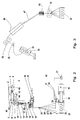
- a thread 1 is spun from a thermoplastic material.
- the thermoplastic material is fed to the extruder by a filling device 3 abandoned.
- the extruder 3 is driven by a motor 4.
- the motor 4 is controlled by a motor controller 8.
- the thermoplastic material is melted in the extruder. This is done on the one hand by the deformation work which is introduced into the material by the extruder.
- a heating device 5 is provided in the form of a resistance heater, which is controlled by a heating controller 43.
- the melt passes through the melt line to the gear pump 9, which is driven by the pump motor 44.
- the melt pressure upstream of the pump is detected by pressure sensor 7 and kept constant by feedback of the pressure signal to the motor control 8.
- the pump motor is controlled by the pump controller 45 in such a way that the pump speed can be set sensitively.
- the pump 9 conveys the melt flow to the heated spinning box 10, on the underside of which the spinneret 11 is located in a nozzle pot 53 (cf. FIG. 4).
- the melt emerges from the spinneret 11 in the form of fine filament strands 12.
- the filament strands pass through a cooling shaft 14.
- an air flow is directed transversely or radially onto the filament sheet by blowing 15 and is thereby cooled.
- the filament sheet is combined into a thread 1 by a preparation roller 13 and provided with a preparation liquid.
- the thread is drawn out of the cooling shaft and from the spinneret through a take-off godet 16.
- the thread wraps around the trigger godet several times.
- an overflow roller 17 is arranged which is crossed over to the godet 16.
- the overflow roller 17 is freely rotatable.
- the godet 16 is powered by a godet motor 18 and frequency generator 22 driven at a preset speed. This withdrawal speed is many times higher than the natural exit speed of the filaments from the spinneret 11.
- the speed of the take-off godet 16 can be adjusted. This determines the speed at which the thread 1 is drawn off from the nozzle plate 11.
- the take-off godet 16 is followed by a draw godet 19 with a further overflow roller 20.
- the structure of both of them corresponds to that of the take-off godet 16 with overflow roller 17.
- the stretch motor 21 with the frequency generator 23 is used to drive the draw godet 19 Frequency generator 24 predetermined evenly.
- the speed of the take-off godet 16 or the stretch godet 19 can be set individually on the frequency converters 22 and 23.
- the speed level of the take-off godet 16 and the stretching godet 19, on the other hand, is set collectively on the frequency converter 24.
- the thread 1 arrives at the so-called “head thread guide” 25 and from there into the traversing triangle 26.
- the following description relates to the winding stage of the process according to FIG. 1 and the process according to FIG. 2 in the same way.
- the traversing device is not shown in both figures.
- a reversing thread roller and a traversing thread guide guided therein which guides the thread back and forth over the length of the bobbin 33.
- the thread wraps around a contact roller 28 behind the traversing device 27.
- the contact roller 28 lies on the surface of the bobbin 33. It is used to measure the surface speed of the coil 33.
- the coil 33 is formed on a sleeve 35.
- the sleeve 35 is clamped on a winding spindle 34.
- the spindle 34 is driven by the spindle motor 36 and spindle control 37 in such a way that the surface speed of the coil 33 remains constant.
- the speed of rotation of the freely rotatable contact roller 28 on the contact roller shaft 29 is scanned and corrected by means of a ferromagnetic insert 30 and a magnetic pulse generator 31.
- the winding speed can be matched to the peripheral speed of the stretching godet 19 by adjusting the spindle control 37.
- the thread running from the take-off godet 16 is guided directly to the head thread guide 25 and into the traversing triangle 26.
- a coordination between the circumferential speed of the winding spindle 33 and the take-off speed, which is predetermined by the take-off godet 16, takes place in a corresponding manner.
- the peripheral speed of the bobbin 33 which is scanned and corrected by the contact roller 28, is slightly lower than the peripheral speed of the upstream godets 16 and 19, respectively.
- the wound thread speed is namely geometrical Sum of the peripheral speed of the coil 33 and the traversing speed of the traversing device 27, not shown.
- FIG. 3 schematically shows a stretch texturing process.
- the bobbin 33 with pre-oriented thread which was produced in the spinning process according to FIG. 2, is presented to a stretch texturing machine.
- the pre-oriented thread is guided through thread guide 38 to an input delivery unit 39, from there through the heater 46, through the cooling rail 47, through the friction false twister and to the output delivery unit 50. It is then wound on the spool 52.
- the delivery mechanisms 39 and 50 are driven at different speeds. As a result, the necessary stretching takes place in the false twist zone between these supplying plants simultaneously with the heating and false twist texturing.
- FIGS. 1 and 2 and 3 are described in detail below.
- a thread with a final titer of 2 filament titer can be generated.
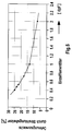
- the take-off speed should be 3,000 m / min. Under normal circumstances, i.e. without heating the nozzle plate, this results in an elongation at break of the thread produced of 120%. That is, in other words, the pre-oriented, drawn thread can be stretched to 220% of its length until it breaks. It follows that the draw ratio is about 2/3 of this value, e.g. B. is 1: 1.6. This results in a take-off speed of 4,800 m / min. With a single filament titer of - as mentioned - 2 den / filament and a filament number of 72, this results in a total denier of 150 den.
- the take-off speeds are now increased to 4,000 m / min.
- a draw ratio is selected approximately in the range of 2/3, the draw ratio is 1: 1.2. This means that the withdrawal speed has not increased.
- a radiator according to FIG. 4 is used underneath the nozzle plate.
- This radiator is described in the following for the process according to FIGS. 1 and 2 in the same way.
- the nozzle plate 11 is seated in the nozzle pot 53.
- the nozzle pot 53 is accommodated in the heating box 10.
- the heater box 10 is heated. Details are not shown here.
- the radiation heater 56 is located below and in direct connection to the nozzle plate.
- the radiation heater 56 is designed as a ring and made of steel. Its inner surface 58 facing the center is formed by a conical surface which faces the nozzle plate. A suitable cone angle (total angle) is z. B. 30 to 40 °.
- In the radiant heater is an annular one Heating tape 57 inserted. It is a resistance heating wire. This resistance heating wire allows the radiant heater to glow red-hot to temperatures above 300 ° to approx. 800 °. Very effective temperatures result in the temperature range between 450 and 700 °.
- the blower 51 follows below the radiant heater as described.
- the extent of the productivity increase depends on the one hand on the irradiation temperature and on the other hand on the thread titer. With larger thread titers, the effect is less or the illumination temperature will have to be chosen higher.
- the connection can be determined in individual cases by experiment.
- the procedure for the method according to FIG. 2 is as follows: To be manufactured z. B. a textured thread 55 f 109, ie a thread of 55 den and 109 individual filaments. This means that each thread has a single denier of 0.5 den per filament (dpf).
- the stretching is determined at 1.6 as optimal for the stretch texturing process. This stretching allows good crimping and a safe texturing process without filament breaks.
- This draw ratio means that a pre-oriented thread has to be placed on bobbin 33, which has a titer of 88 den with 109 filaments. In order to pre-orient such a thread so that the draw ratio can be maintained at 1.6, a 1/2 to 1/3 higher elongation at break must be set.
- the elongation at break must be approximately 220%. From the diagram according to FIG. 5 or the table, this results in a take-off speed of 2,600 m / min, which is set in the process according to FIG. 2 by take-off godets 16.
- the delivery rate on the pump In order to produce a pre-oriented thread of 88 den at a take-up speed of 2,600 m / min, the delivery rate on the pump must be set to 25.5 g / min for each spinning station. An increase in the delivery rate is not possible, since otherwise the withdrawal speed and thus the stretchability will also be changed.
- the stretchability which is specified by the texturer, thus limits the productivity of the producer of the pre-oriented thread.
- a textured thread 55 f 109 is to be produced.
- the take-off speed and winding speed of 3,000 m / min should not be exceeded in the winding zone.
- process difficulties with sensitive yarns can also be caused by the mechanical design of the rewinder, the maximum speed of which is limited.
- the drawing ratio can thus be set at approximately 2/3 of this value, ie: 1.45.
- the peculiarity of the invention is that the melt is heated in the nozzle plate.
- the nozzle plate is heated, in addition to the supply of heat that occurs from the melt and from the surrounding spin pot and the surrounding spin box.
- the temperature of the nozzle plate is preferably increased by at least 5 ° C. and up to 40 ° C. In the experiments, there were advantageous increases in temperature of 8 to 20 ° C.
- the starting point is always the temperature that results from the contact of the nozzle plate with the melt and the heated spinning box. At - normal travel - relatively low temperature of the nozzle plate, the heating by additional heat must be correspondingly greater.
- the annular radiator has the advantage over the fact that, on the one hand, it prevents the nozzle and in particular the underside of the nozzle from being hit directly by the blowing underneath. On the other hand, there is sufficient air exchange within the annular radiator to remove vapors, especially monomers and oligomers, and to avoid impermissible deposits on the underside of the nozzle. To clean the underside of the nozzle, the radiator is hung on one side in a hinge so that it can be folded down.
Landscapes
- Engineering & Computer Science (AREA)
- Textile Engineering (AREA)
- Mechanical Engineering (AREA)
- Spinning Methods And Devices For Manufacturing Artificial Fibers (AREA)
- Artificial Filaments (AREA)
Applications Claiming Priority (2)
| Application Number | Priority Date | Filing Date | Title |
|---|---|---|---|
| DE19504422 | 1995-02-10 | ||
| DE19504422 | 1995-02-10 |
Publications (3)
| Publication Number | Publication Date |
|---|---|
| EP0726338A2 true EP0726338A2 (fr) | 1996-08-14 |
| EP0726338A3 EP0726338A3 (fr) | 1996-11-06 |
| EP0726338B1 EP0726338B1 (fr) | 2001-11-28 |
Family
ID=7753631
Family Applications (1)
| Application Number | Title | Priority Date | Filing Date |
|---|---|---|---|
| EP96100162A Expired - Lifetime EP0726338B1 (fr) | 1995-02-10 | 1996-01-08 | Procédé de fabrication d'un fil multifilament |
Country Status (6)
| Country | Link |
|---|---|
| US (1) | US5661880A (fr) |
| EP (1) | EP0726338B1 (fr) |
| KR (1) | KR100426837B1 (fr) |
| CN (1) | CN1185374C (fr) |
| DE (1) | DE59608283D1 (fr) |
| TW (1) | TW380174B (fr) |
Cited By (5)
| Publication number | Priority date | Publication date | Assignee | Title |
|---|---|---|---|---|
| US5928587A (en) * | 1996-08-28 | 1999-07-27 | Barmag Ag | Process and apparatus for cooling melt spun filaments during formation of a multi-filament yarn |
| US6129882A (en) * | 1998-03-13 | 2000-10-10 | Sml Maschinengesellschaft M.B.H. | Apparatus for manufacturing multifilament threads |
| CN103114365A (zh) * | 2013-03-13 | 2013-05-22 | 盛虹集团有限公司 | 复合丝雪纺面料中纬丝的织造方法 |
| CN103556241A (zh) * | 2013-10-30 | 2014-02-05 | 苏州龙杰特种纤维股份有限公司 | 纺织纤维生产系统 |
| CN105821498A (zh) * | 2016-05-27 | 2016-08-03 | 浙江显昱纤维织染制衣有限公司 | 一种纺丝机的拉伸结构 |
Families Citing this family (17)
| Publication number | Priority date | Publication date | Assignee | Title |
|---|---|---|---|---|
| CN1089380C (zh) * | 1998-05-22 | 2002-08-21 | 孙世杰 | 高速、低成本全牵伸长丝纺丝工艺及其设备 |
| US6336801B1 (en) * | 1999-06-21 | 2002-01-08 | Kimberly-Clark Worldwide, Inc. | Die assembly for a meltblowing apparatus |
| US6332994B1 (en) | 2000-02-14 | 2001-12-25 | Basf Corporation | High speed spinning of sheath/core bicomponent fibers |
| CA2410415A1 (fr) * | 2000-06-23 | 2002-01-03 | E.I. Du Pont De Nemours And Company | Anneau de distribution de vapeur pour machines a filer |
| AU2001294554A1 (en) | 2000-09-15 | 2002-03-26 | First Quality Fibers, Inc. | Apparatus for manufacturing optical fiber made of semi-crystalline polymer |
| DE10227290A1 (de) * | 2002-06-19 | 2004-01-08 | Barmag Ag | Vorrichtung zum Führen, Behandeln und Fördern von zumindest einem Faden |
| DE10235936A1 (de) * | 2002-08-06 | 2004-02-19 | Barmag Ag | Vorrichtung zum Spinnen und Aufwickeln |
| EP1585850A1 (fr) * | 2003-01-24 | 2005-10-19 | Saurer GmbH & Co. KG | Dispositif et procede pour texturer plusieurs fils mixtes synthetiques |
| DE102005045496A1 (de) * | 2005-09-23 | 2007-03-29 | Saurer Gmbh & Co. Kg | Vorrichtung zum Schmelzspinnen und Abziehen eines Fadens |
| DE102010006659A1 (de) * | 2010-02-03 | 2011-08-04 | Oerlikon Textile GmbH & Co. KG, 42897 | Vorrichtung zum Abziehen oder Führen synthetischer Fäden |
| US8282384B1 (en) * | 2011-04-15 | 2012-10-09 | Thomas Michael R | Continuous curing and post curing apparatus |
| TWM427214U (en) | 2011-12-13 | 2012-04-21 | Zhi-Hong Chen | Sealed oil path type roller apparatus |
| WO2019059560A1 (fr) * | 2017-09-22 | 2019-03-28 | 코오롱인더스트리 주식회사 | Fibre de polyéthylène téréphtalate à résistance élevée et son procédé de fabrication |
| JP7773880B2 (ja) * | 2021-10-01 | 2025-11-20 | Tmtマシナリー株式会社 | 紡糸設備、及び紡糸巻取設備 |
| CN114808158B (zh) * | 2022-04-07 | 2023-06-09 | 桐昆集团浙江恒盛化纤有限公司 | 高匀度纤维的生产方法及其生产设备 |
| WO2025192660A1 (fr) * | 2024-03-13 | 2025-09-18 | 株式会社クラレ | Dispositif de chauffage annulaire |
| CN118480871B (zh) * | 2024-07-09 | 2024-11-19 | 江苏恒力化纤股份有限公司 | 一种超细丝的生产方法 |
Family Cites Families (25)
| Publication number | Priority date | Publication date | Assignee | Title |
|---|---|---|---|---|
| DE1905507A1 (de) * | 1969-02-05 | 1970-08-20 | Hoechst Ag | Verfahren und Vorrichtung zum Schmelzspinnen von synthetischen Polymeren |
| US3771307A (en) * | 1971-08-24 | 1973-11-13 | Du Pont | Drawing and bulking polyester yarns |
| SE392299B (sv) * | 1971-08-24 | 1977-03-21 | Du Pont | Forfarande och medel for framstellning av garn med dragen och snodd textur |
| DE2254998B2 (de) * | 1972-11-10 | 1975-07-10 | Barmag Barmer Maschinenfabrik Ag, 5600 Wuppertal | Verfahren zur Herstellung von Kord aus Chemiefasern |
| US3772872A (en) * | 1973-03-27 | 1973-11-20 | Du Pont | Polyester yarn for draw-texturing process |
| US4235000A (en) * | 1976-06-04 | 1980-11-25 | Phillips Petroleum Company | Method for straightening textured yarn |
| DE2653010A1 (de) * | 1976-11-22 | 1978-05-24 | Barmag Barmer Maschf | Verfahren zur herstellung eines faserkabels |
| JPS5721508A (en) * | 1980-07-10 | 1982-02-04 | Toray Ind Inc | Melt spinning apparatus |
| JPS5761709A (en) * | 1980-10-02 | 1982-04-14 | Teijin Ltd | Preparation of bundled filamentary fibrous material and molding apparatus |
| JPS6026841B2 (ja) * | 1981-12-25 | 1985-06-26 | 帝人株式会社 | 溶融紡糸方法 |
| ZA83849B (en) * | 1982-02-22 | 1984-02-29 | Goodyear Tire & Rubber | Process for the production of high strength polyester yarn |
| JPS591713A (ja) * | 1982-06-22 | 1984-01-07 | Toray Ind Inc | ポリエチレンテレフタレ−ト系繊維の製造方法 |
| JPS6059119A (ja) * | 1983-09-09 | 1985-04-05 | Toray Ind Inc | ポリエステル繊維の製造方法 |
| US4731217A (en) * | 1984-08-09 | 1988-03-15 | Barmag Ag | Method for melt spinning thermoplastic filament yarn |
| DE3528306C2 (de) * | 1984-08-09 | 1994-02-24 | Barmag Barmer Maschf | Verfahren zum Spinnen thermoplastischer Fäden |
| EP0201189B2 (fr) * | 1985-04-22 | 1995-02-15 | BASF Corporation | Procédé de filage à grande vitesse de fibres de polyamide |
| DE3617248C2 (de) * | 1985-08-30 | 1995-05-24 | Barmag Barmer Maschf | Verfahren zum Herstellen eines Kompositfadens aus Chemiefasern |
| JPS6262917A (ja) * | 1985-09-10 | 1987-03-19 | Mitsubishi Chem Ind Ltd | ピツチ系炭素繊維の製造方法 |
| JPS62177207A (ja) * | 1986-01-27 | 1987-08-04 | Toray Ind Inc | 溶融紡糸方法 |
| JPH0635685B2 (ja) * | 1986-10-16 | 1994-05-11 | 帝人株式会社 | 溶融紡糸装置 |
| JPH0684565B2 (ja) * | 1987-05-06 | 1994-10-26 | 帝人株式会社 | 合成繊維の溶融紡糸装置 |
| JPH01111011A (ja) * | 1987-10-23 | 1989-04-27 | Unitika Ltd | ナイロン46繊維の製造方法 |
| JPH03288617A (ja) * | 1990-04-04 | 1991-12-18 | Toray Ind Inc | 熱可塑性重合体成形物の製造方法 |
| JPH0657563A (ja) * | 1992-08-08 | 1994-03-01 | Teijin Seiki Co Ltd | 延伸仮撚機の運転方法 |
| US5507997A (en) * | 1994-03-31 | 1996-04-16 | Montell North America Inc. | Process for preparing a thermal bondable fiber |
-
1996
- 1996-01-08 EP EP96100162A patent/EP0726338B1/fr not_active Expired - Lifetime
- 1996-01-08 DE DE59608283T patent/DE59608283D1/de not_active Expired - Fee Related
- 1996-02-08 CN CNB961013850A patent/CN1185374C/zh not_active Expired - Fee Related
- 1996-02-09 US US08/598,839 patent/US5661880A/en not_active Expired - Fee Related
- 1996-02-10 KR KR1019960003255A patent/KR100426837B1/ko not_active Expired - Fee Related
- 1996-02-10 TW TW085101688A patent/TW380174B/zh not_active IP Right Cessation
Cited By (5)
| Publication number | Priority date | Publication date | Assignee | Title |
|---|---|---|---|---|
| US5928587A (en) * | 1996-08-28 | 1999-07-27 | Barmag Ag | Process and apparatus for cooling melt spun filaments during formation of a multi-filament yarn |
| US6129882A (en) * | 1998-03-13 | 2000-10-10 | Sml Maschinengesellschaft M.B.H. | Apparatus for manufacturing multifilament threads |
| CN103114365A (zh) * | 2013-03-13 | 2013-05-22 | 盛虹集团有限公司 | 复合丝雪纺面料中纬丝的织造方法 |
| CN103556241A (zh) * | 2013-10-30 | 2014-02-05 | 苏州龙杰特种纤维股份有限公司 | 纺织纤维生产系统 |
| CN105821498A (zh) * | 2016-05-27 | 2016-08-03 | 浙江显昱纤维织染制衣有限公司 | 一种纺丝机的拉伸结构 |
Also Published As
| Publication number | Publication date |
|---|---|
| TW380174B (en) | 2000-01-21 |
| CN1136093A (zh) | 1996-11-20 |
| KR100426837B1 (ko) | 2004-06-18 |
| EP0726338A3 (fr) | 1996-11-06 |
| DE59608283D1 (de) | 2002-01-10 |
| EP0726338B1 (fr) | 2001-11-28 |
| US5661880A (en) | 1997-09-02 |
| KR960031662A (ko) | 1996-09-17 |
| CN1185374C (zh) | 2005-01-19 |
Similar Documents
| Publication | Publication Date | Title |
|---|---|---|
| EP0726338B1 (fr) | Procédé de fabrication d'un fil multifilament | |
| EP1527217B1 (fr) | Dispositif de filage et d'enroulement | |
| EP0845550B1 (fr) | Procédé et dispositifs pour filer et enrouler un fil | |
| EP2283174B1 (fr) | Procédé de filage à l'état fondu, d'étirage et d'enroulement d'un fil multifilament, et dispositif destiné à la réalisation du procédé | |
| DE19535143B4 (de) | Vorrichtung und Verfahren zur thermischen Behandlung von Fasern | |
| EP2456913B1 (fr) | Procédé de filage à l'état fondu, d'étirage et de déroulement d'un filé multifilament, et procédé d'exécution du procédé | |
| EP2318577B1 (fr) | Procédé de filage par fusion, d'étirage et d'enroulement un fil multifilament et dispositif de mise en oeuvre de ce procédé | |
| EP2456912A1 (fr) | Procédé pour enlever et étirer un fil synthétique, et dispositif pour la mise en oeuvre de ce procédé | |
| EP1045930B1 (fr) | Procede et dispositif pour la production d'un fil hautement oriente | |
| EP0373519B1 (fr) | Procédé de fabrication d'un fil texturé par jet d'air | |
| DE102009037125A1 (de) | Verfahren zum Schmelzspinnen, Verstrecken und Aufwickeln eines multifilen Fadens sowie eine Vorrichtung zur Durchführung des Verfahrens | |
| EP1583855B1 (fr) | Procede et dispositif pour filer et onduler un fil synthetique | |
| EP0826802B1 (fr) | Procédé et dispositif de filature des fils multifilaments | |
| DE19506369A1 (de) | Verfahren und Vorrichtung zum Heizen eines synthetischen Fadens | |
| EP0731196B1 (fr) | Procédé pour le filage, l'étirage et le bobinage d'un fil synthétique | |
| DE102004007074A1 (de) | Verfahren zum Anlegen eines Fadens und Falschdralltexturiermaschine | |
| DE2741193B2 (de) | Verfahren und Vorrichtung zur Herstellung von Filamenten aus thermoplastischen Materialien | |
| DE102015016800A1 (de) | Verfahren zum Schmelzspinnen, Abziehen, Verstrecken, Relaxieren und Aufwickeln eines synthetischen Fadens für technische Anwendungszwecke und eine zugehörige Vorrichtung | |
| DE19909073A1 (de) | Vorrichtung und Verfahren zum Verstrecken eines synthetischen Fadens | |
| DE102005045496A1 (de) | Vorrichtung zum Schmelzspinnen und Abziehen eines Fadens | |
| EP1819854A1 (fr) | Procede et dispositif de guidage et de tourbillonnement d'un fil multfilament | |
| EP1200655B1 (fr) | Procede pour la production de fils mixtes | |
| EP0946799B1 (fr) | Procede et dispositif de fabrication de fibres industrielles en polyester | |
| WO2002090633A2 (fr) | Procede et dispositif pour produire un fil lisse a faible retrait | |
| EP1838908A1 (fr) | Procede et dispositif pour filage par fusion et texturation d'une pluralite de fils multifilaments |
Legal Events
| Date | Code | Title | Description |
|---|---|---|---|
| PUAI | Public reference made under article 153(3) epc to a published international application that has entered the european phase |
Free format text: ORIGINAL CODE: 0009012 |
|
| AK | Designated contracting states |
Kind code of ref document: A2 Designated state(s): CH DE ES FR GB IT LI |
|
| PUAL | Search report despatched |
Free format text: ORIGINAL CODE: 0009013 |
|
| AK | Designated contracting states |
Kind code of ref document: A3 Designated state(s): CH DE ES FR GB IT LI |
|
| 17P | Request for examination filed |
Effective date: 19961216 |
|
| 17Q | First examination report despatched |
Effective date: 19980304 |
|
| GRAG | Despatch of communication of intention to grant |
Free format text: ORIGINAL CODE: EPIDOS AGRA |
|
| GRAG | Despatch of communication of intention to grant |
Free format text: ORIGINAL CODE: EPIDOS AGRA |
|
| GRAH | Despatch of communication of intention to grant a patent |
Free format text: ORIGINAL CODE: EPIDOS IGRA |
|
| GRAH | Despatch of communication of intention to grant a patent |
Free format text: ORIGINAL CODE: EPIDOS IGRA |
|
| GRAA | (expected) grant |
Free format text: ORIGINAL CODE: 0009210 |
|
| AK | Designated contracting states |
Kind code of ref document: B1 Designated state(s): CH DE ES FR GB IT LI |
|
| REG | Reference to a national code |
Ref country code: CH Ref legal event code: EP |
|
| REG | Reference to a national code |
Ref country code: CH Ref legal event code: NV Representative=s name: HERMANN KAHLHOEFER |
|
| REG | Reference to a national code |
Ref country code: GB Ref legal event code: IF02 |
|
| REF | Corresponds to: |
Ref document number: 59608283 Country of ref document: DE Date of ref document: 20020110 |
|
| GBT | Gb: translation of ep patent filed (gb section 77(6)(a)/1977) |
Effective date: 20020128 |
|
| PG25 | Lapsed in a contracting state [announced via postgrant information from national office to epo] |
Ref country code: ES Free format text: LAPSE BECAUSE OF FAILURE TO SUBMIT A TRANSLATION OF THE DESCRIPTION OR TO PAY THE FEE WITHIN THE PRESCRIBED TIME-LIMIT Effective date: 20020530 |
|
| PLBQ | Unpublished change to opponent data |
Free format text: ORIGINAL CODE: EPIDOS OPPO |
|
| PLBI | Opposition filed |
Free format text: ORIGINAL CODE: 0009260 |
|
| 26 | Opposition filed |
Opponent name: ZIMMER A.G. Effective date: 20020802 |
|
| PLBF | Reply of patent proprietor to notice(s) of opposition |
Free format text: ORIGINAL CODE: EPIDOS OBSO |
|
| PLBF | Reply of patent proprietor to notice(s) of opposition |
Free format text: ORIGINAL CODE: EPIDOS OBSO |
|
| RAP2 | Party data changed (patent owner data changed or rights of a patent transferred) |
Owner name: SAURER GMBH & CO. KG |
|
| PGFP | Annual fee paid to national office [announced via postgrant information from national office to epo] |
Ref country code: GB Payment date: 20050112 Year of fee payment: 10 |
|
| PGFP | Annual fee paid to national office [announced via postgrant information from national office to epo] |
Ref country code: FR Payment date: 20050118 Year of fee payment: 10 |
|
| PG25 | Lapsed in a contracting state [announced via postgrant information from national office to epo] |
Ref country code: GB Free format text: LAPSE BECAUSE OF NON-PAYMENT OF DUE FEES Effective date: 20060108 |
|
| PG25 | Lapsed in a contracting state [announced via postgrant information from national office to epo] |
Ref country code: FR Free format text: LAPSE BECAUSE OF NON-PAYMENT OF DUE FEES Effective date: 20060131 |
|
| GBPC | Gb: european patent ceased through non-payment of renewal fee |
Effective date: 20060108 |
|
| REG | Reference to a national code |
Ref country code: FR Ref legal event code: ST Effective date: 20060929 |
|
| RAP2 | Party data changed (patent owner data changed or rights of a patent transferred) |
Owner name: OERLIKON TEXTILE GMBH & CO. KG |
|
| PGFP | Annual fee paid to national office [announced via postgrant information from national office to epo] |
Ref country code: DE Payment date: 20080218 Year of fee payment: 13 |
|
| PLBP | Opposition withdrawn |
Free format text: ORIGINAL CODE: 0009264 |
|
| PLBD | Termination of opposition procedure: decision despatched |
Free format text: ORIGINAL CODE: EPIDOSNOPC1 |
|
| RAP2 | Party data changed (patent owner data changed or rights of a patent transferred) |
Owner name: OERLIKON TEXTILE GMBH & CO. KG |
|
| PLBM | Termination of opposition procedure: date of legal effect published |
Free format text: ORIGINAL CODE: 0009276 |
|
| STAA | Information on the status of an ep patent application or granted ep patent |
Free format text: STATUS: OPPOSITION PROCEDURE CLOSED |
|
| 27C | Opposition proceedings terminated |
Effective date: 20080720 |
|
| PGFP | Annual fee paid to national office [announced via postgrant information from national office to epo] |
Ref country code: CH Payment date: 20090130 Year of fee payment: 14 |
|
| PGFP | Annual fee paid to national office [announced via postgrant information from national office to epo] |
Ref country code: IT Payment date: 20090127 Year of fee payment: 14 |
|
| PG25 | Lapsed in a contracting state [announced via postgrant information from national office to epo] |
Ref country code: DE Free format text: LAPSE BECAUSE OF NON-PAYMENT OF DUE FEES Effective date: 20090801 |
|
| REG | Reference to a national code |
Ref country code: CH Ref legal event code: PL |
|
| PG25 | Lapsed in a contracting state [announced via postgrant information from national office to epo] |
Ref country code: LI Free format text: LAPSE BECAUSE OF NON-PAYMENT OF DUE FEES Effective date: 20100131 Ref country code: CH Free format text: LAPSE BECAUSE OF NON-PAYMENT OF DUE FEES Effective date: 20100131 |
|
| PG25 | Lapsed in a contracting state [announced via postgrant information from national office to epo] |
Ref country code: IT Free format text: LAPSE BECAUSE OF NON-PAYMENT OF DUE FEES Effective date: 20100108 |