EP0729820A1 - Moule pour fabriquer un article creux moulé en matière thermoplastique et procédé pour fabriquer un article creux moulé en matière thermoplastique utilisant ce moule - Google Patents
Moule pour fabriquer un article creux moulé en matière thermoplastique et procédé pour fabriquer un article creux moulé en matière thermoplastique utilisant ce moule Download PDFInfo
- Publication number
- EP0729820A1 EP0729820A1 EP96103337A EP96103337A EP0729820A1 EP 0729820 A1 EP0729820 A1 EP 0729820A1 EP 96103337 A EP96103337 A EP 96103337A EP 96103337 A EP96103337 A EP 96103337A EP 0729820 A1 EP0729820 A1 EP 0729820A1
- Authority
- EP
- European Patent Office
- Prior art keywords
- mold
- cavity
- molded article
- gas
- thermoplastic resin
- Prior art date
- Legal status (The legal status is an assumption and is not a legal conclusion. Google has not performed a legal analysis and makes no representation as to the accuracy of the status listed.)
- Granted
Links
Images



Classifications
-
- B—PERFORMING OPERATIONS; TRANSPORTING
- B29—WORKING OF PLASTICS; WORKING OF SUBSTANCES IN A PLASTIC STATE IN GENERAL
- B29C—SHAPING OR JOINING OF PLASTICS; SHAPING OF MATERIAL IN A PLASTIC STATE, NOT OTHERWISE PROVIDED FOR; AFTER-TREATMENT OF THE SHAPED PRODUCTS, e.g. REPAIRING
- B29C45/00—Injection moulding, i.e. forcing the required volume of moulding material through a nozzle into a closed mould; Apparatus therefor
- B29C45/17—Component parts, details or accessories; Auxiliary operations
- B29C45/1703—Introducing an auxiliary fluid into the mould
- B29C45/1734—Nozzles therefor
- B29C45/1736—Nozzles therefor provided with small holes permitting the flow of gas therethrough, e.g. using a porous element of sintered material
-
- B—PERFORMING OPERATIONS; TRANSPORTING
- B29—WORKING OF PLASTICS; WORKING OF SUBSTANCES IN A PLASTIC STATE IN GENERAL
- B29C—SHAPING OR JOINING OF PLASTICS; SHAPING OF MATERIAL IN A PLASTIC STATE, NOT OTHERWISE PROVIDED FOR; AFTER-TREATMENT OF THE SHAPED PRODUCTS, e.g. REPAIRING
- B29C45/00—Injection moulding, i.e. forcing the required volume of moulding material through a nozzle into a closed mould; Apparatus therefor
- B29C45/17—Component parts, details or accessories; Auxiliary operations
- B29C45/46—Means for plasticising or homogenising the moulding material or forcing it into the mould
- B29C45/57—Exerting after-pressure on the moulding material
-
- B—PERFORMING OPERATIONS; TRANSPORTING
- B29—WORKING OF PLASTICS; WORKING OF SUBSTANCES IN A PLASTIC STATE IN GENERAL
- B29C—SHAPING OR JOINING OF PLASTICS; SHAPING OF MATERIAL IN A PLASTIC STATE, NOT OTHERWISE PROVIDED FOR; AFTER-TREATMENT OF THE SHAPED PRODUCTS, e.g. REPAIRING
- B29C45/00—Injection moulding, i.e. forcing the required volume of moulding material through a nozzle into a closed mould; Apparatus therefor
- B29C45/17—Component parts, details or accessories; Auxiliary operations
- B29C45/1703—Introducing an auxiliary fluid into the mould
- B29C45/1704—Introducing an auxiliary fluid into the mould the fluid being introduced into the interior of the injected material which is still in a molten state, e.g. for producing hollow articles
- B29C45/1705—Introducing an auxiliary fluid into the mould the fluid being introduced into the interior of the injected material which is still in a molten state, e.g. for producing hollow articles using movable mould parts
-
- B—PERFORMING OPERATIONS; TRANSPORTING
- B29—WORKING OF PLASTICS; WORKING OF SUBSTANCES IN A PLASTIC STATE IN GENERAL
- B29C—SHAPING OR JOINING OF PLASTICS; SHAPING OF MATERIAL IN A PLASTIC STATE, NOT OTHERWISE PROVIDED FOR; AFTER-TREATMENT OF THE SHAPED PRODUCTS, e.g. REPAIRING
- B29C45/00—Injection moulding, i.e. forcing the required volume of moulding material through a nozzle into a closed mould; Apparatus therefor
- B29C45/17—Component parts, details or accessories; Auxiliary operations
- B29C45/1703—Introducing an auxiliary fluid into the mould
- B29C45/1734—Nozzles therefor
Definitions
- the present invention relates to a mold for production of a thermoplastic resin molded article having a hollow part, and a process for production of a thermoplastic resin molded article having a hollow part using the same mold.
- a hollow thermoplastic resin molded article and a thermoplastic resin are referred to as “hollow molded article” and “resin”, respectively.
- Hollow molded articles have been produced, for example, by feeding molten resin into a cavity of a mold, provided with a movable or fixed gas introducing pin, as shown in Fig. 16, and directly introducing compressed air or high-pressure gas into the molten resin through a tip of the gas introducing pin which protrudes into the cavity (see, for example, JP-A 3-164222 and JP-A 5-16177).
- the mold used in this method is costly due to the presence of the gas introducing pin and the design of the mold is restricted due to the larger space occupied by the gas introducing member in the mold.
- a gas-ejecting hole of the gas introducing pin is easily choked with resin, maintenance of the gas introducing pin is costly and time consuming.
- a trace formed by pulling out the gas introducing pin after molding remains on the surface of the hollow molded articles produced by this method. Further, choking of the gas-ejecting hole with resin prevents gas introduction, which decreases the amount of introduced gas and leads to formation of an insufficient hollow part.
- the object of the present invention is to provide a mold which can successfully form a hollow part in the interior of a thermoplastic resin molded article and yield a hollow molded article having a good appearance and a process for production of a hollow molded article using the same mold.
- the present invention provides a mold for production of a hollow molded article which includes a pair of a female and a male mold members, wherein a gas passage is provided in either of the female or the male mold member, and a gas introducing member for introducing a gas into a cavity formed between the female and the male mold members is provided in communication with the gas passage such that a tip of the gas introducing member does not protrude into the cavity.
- the gas introducing member has a gas path which is open at its tip and is in communication with the gas passage in the mold. In the mold of the present invention, the gas introducing member is provided such that its tip does not protrude into the cavity.
- the gas passage provided in either of the female or the male mold member may be directly opened on a cavity plane instead of through the gas introducing member.
- the cavity plane provided with the gas passage may be further provided with a lagging material.
- a lagging material since the formation of a skin layer on a surface of a resin is prevented by the action of the lagging material, the introduction of gas into a molten resin is promoted.
- Fig. 1 is a schematic cross-sectional view of the present mold for production of a hollow molded article.
- Fig. 2 is a schematic enlarged cross-sectional view illustrating an area near the gas introducing member of one embodiment of the present mold for production of a hollow molded article.
- Fig. 3 is a schematic enlarged cross-sectional view illustrating an area near the gas introducing member of another embodiment of the present mold for production of a hollow molded article.
- Fig. 4 is a schematic enlarged cross-sectional view illustrating an area near an opening on the cavity plane from the gas passage in the present mold for production of a hollow molded article.
- Fig. 5 is a schematic enlarged cross-sectional view of the gas introducing member.
- a circular molded piece or a square molded piece is provided with a groove or a penetrating hole as a gas path in Fig. 5A or in Fig. 5B, respectively.
- Fig. 6 is a view illustrating one state where a hollow molded article is being produced by injection-compression molding using the present mold.
- Fig. 7 is a view illustrating another state where a hollow molded article is being produced by injection-compression molding using the present mold.
- Fig. 8 is a schematic cross-sectional view of one embodiment of the present mold for production of a hollow molded article having a lagging material on the cavity plane.
- Fig. 9 is a schematic cross-sectional view of another embodiment of the present mold for production of a hollow molded article having a lagging material on the cavity plane.
- Fig. 10 is a schematic enlarged cross-sectional view illustrating one embodiment of an area near the gas introducing member and the lagging material in the present mold for production of a hollow molded article.
- Fig. 11 is a schematic enlarged cross-sectional view illustrating another embodiment of an area near the gas introducing member and the lagging material in the present mold for production of a hollow molded article.
- Fig. 12 is a schematic enlarged view illustrating an area near an opening on the cavity plane from the gas passage in the present mold for production of a hollow molded article.
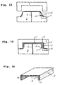
- Fig. 13 is a view illustrating a further state where a hollow molded article is being produced by injection-compression molding using the present mold.
- Fig. 14 is a view illustrating a still further state where a hollow molded article is being produced by injection-compression molding using the present mold.
- Fig. 15 is a perspective of a hollow molded article produced by using the present mold.
- Fig. 16 is a schematic enlarged cross-sectional view illustrating an area near a gas introducing pin in the prior art mold.
- Figs. 1 to 3 are schematic cross-sectional views illustrating embodiments of a mold of the present invention, which include a pair of a female and a male mold members 1 , 2 .
- the female and the male mold members are designed so that a molded article having a partial thick part is formed in a cavity 4 formed between cavity planes 31 and 32 .
- a gas passage 6 is provided in either of the female or the male mold member (provided in the male mold member 2 , in these embodiments). One end of the gas passage is connected to a gas feeding apparatus (not shown).
- a gas introducing member 5 for introducing gas fed from the gas passage into the cavity is provided at a position of the cavity plane provided with the gas passage, which corresponds to a position where a thick part of a molded article is formed, such that a tip of the gas introducing member does not protrude into the cavity.
- the cavity and the gas passage communicate via a gas path 7 such as a groove, a penetrating hole or the like provided on or in the gas introducing member.
- the cavity 4 and the gas passage 6 communicate via the gas path 7 provided in the gas introducing member 5 and the gas introducing member is provided in the mold such that its tip does not protrude into the cavity.
- the gas introducing member 5 may be any structure which enables gas to be passed through its outer periphery part and/or interior when provided in the mold, such that the tip does not protrude from the cavity plane. Molded pieces formed of a porous material which have many open-microcells which function as gas paths may preferably be used. Examples such porous materials include sintered metals, such as sintered copper and sintered stainless steel, sintered resin such as sintered fluorine plastic, expanded aluminum and porous ceramics, all of which may be used to form the gas introducing member in the present invention.
- molded pieces having grooves or penetrating holes extending to the tip thereof at the outer periphery part and/or interior part, whether porous or nonporous, for example, as illustrated in Figs. 5A and 5B, may be used as a gas introducing member.
- the grooves provided on the outer periphery part of the molded piece and the penetrating holes provided in the interior of the molded piece function as a gas path 7 .
- the cross-sectional shape of the gas path relative to a gas flowing direction may be formed in any suitable manner, such as circular, rectangular, semicircular, V-shape, U-shape etc.
- a gas introducing member of this sort is usually formed from a rigid material which has excellent heat resistance properties and is resistant to the pressure applied during resin molding. Examples of materials include metal and ceramics.
- Gas is preferably introduced as a divided stream into the cavity 4 through the gas introducing member 5 . Therefore, it is preferable that many gas paths are formed at the tip of the gas introducing member. When porous material is used, since the many fine holes of the material produce a divided stream, it may be used as the gas introducing member once molded into the desired shape. On the other hand, when the gas introducing member is a molded piece having gas paths formed on its outer peripheral part and/or interior, it is preferable that a plurality of grooves and penetrating holes are provided as a gas path.
- the cross-sectional area of the opening into the cavity from each gas path is preferably not larger than 0.03 mm 2 .
- the sectional area of the opening of each fine hole is preferably not larger than 0.03 mm 2 .
- the above sectional area in preferably smaller.
- the size of the gas introducing member 5 is not specifically limited, but the cross-sectional area of the gas introducing member, parallel to the cavity plane, is usually not larger than 2 cm 2 in order to facilitate design of the mold.
- the length from the tip to the rear tip in the gas introducing member is usually at longest about 30 mm, and preferably shorter than 20 mm.
- the shape of the gas introducing member is arbitrary, for example, cylindrical or prism-like.
- the gas introducing member 5 may be provided in either the female or the male mold member and preferably near a position corresponding to a position at which a hollow part is formed in the molded article.
- a plurality of gas introducing members may be provided depending upon the size of the cavity plane, and the number and size of a hollow part to be formed in the molded article. Respective gas introducing members may be the same or different. For example, as shown in Fig.
- the gas introducing member 5 should be situated at a position on the cavity plane of the molded article which corresponds to a position where the thick part is formed.
- a plurality of gas introducing members may be provided depending upon the size of the cavity plane and the size and the shape of the thick part in which the hollow part is formed.
- the gas introducing member 5 is preferably fitted into a concave part 8 formed in the mold, and the gas passage 6 is formed to open into the bottom part and/or the side part of the gas introducing member 5 .
- the gas introducing member 5 is fitted so as to tightly contact the outer peripheral plane of the gas introducing member with the inner wall of the concave part so that the gas introducing member will not be dislodged by the pressure of the gas being fed through it, and will not be detached from the concave part due to attachment to resin upon removal of the hollow molded article from the mold.
- the gas introducing member is preferably shaped such that the area of the tip is slightly larger than that of the opening of the concave part before being inserted into the concave part because a gas introducing member with this shape is not easily detached from the concave part when fitted into the concave part.
- the tip of the gas introducing member 5 does not protrude into the cavity.
- the tip of the gas introducing member and the cavity may form a continuous plane (plane having no level difference at a boundary) (Fig. 2) or the tip of the gas introducing member may be situated at a position lower than the surrounding cavity plane (Fig. 3).
- the depth of the concave part is preferably at most 30 mm and the distance between the tip of the gas introducing member and the cavity plane preferably is not very large.
- the present invention also encompasses a mold wherein a gas passage 6 opens directly into the cavity plane instead of through a gas introduction member.
- the area and the shape of the gas passage which opens on the cavity plane are the same as those of the above gas path in the gas introducing member.
- the gas passage is preferably divided into a plurality of ramificated paths having, for example, a rake shape (Fig. 4).
- the area over which the ramificated paths are distributed on the cavity plane is usually not larger than 2 cm 2 .
- the cavity plane 32 provided with the gas passage 6 is preferably provided further with a lagging material 10 (Fig 8 to Fig. 12).
- a lagging material means a member having the function of preventing formation of a skin layer on the surface of the molten resin in contact with the cavity plane by preventing the direct heat transfer between the molten resin fed into the cavity and the mold.
- Two exemplary lagging materials include a thermal insulant and a local-heater.
- a local-heater is referred to as a "heater”.
- the surface of the lagging material provided in the mold preferably forms part of the cavity plane.
- any lagging material 10 is fixed so that it is not protruding from the surrounding cavity plane.
- the lagging material is embedded in the mold so that the surface thereof and the surrounding cavity plane form a continuous plane, that is, a level difference is not formed at the border between the lagging material and the surrounding cavity plane.
- the type of the material is not particularly limited and any material having smaller heat conductivity than that of the material forming the mold may be used.
- Preferred materials for use as the thermal insulant are thermosetting resins such as epoxy resin, glass, pottery, wooden material, and heat-resistant engineering plastic (for example, Ekonol resin). These materials may be used alone or in appropriate combinations.
- a thermal insulant having a rough surface such as wooden material or glass fiber is coated with pottery having a smooth surface.
- the above various materials may be coated with the same material as that from which the mold is formed, but having a thickness which will not adversely affect the thermal insulating abilities of the lagging material.
- the size of the thermal insulant is not limited and is sufficient when the thermal insulating effect prevents the skin layer from being formed on the thermal insulant. This will vary depending upon the various conditions such as the shape and the size of the mold, the kind of thermal insulant being used, the temperature of the molten resin, the temperature of the mold, etc. When the size of the thermal insulant is too large, the ability to cool the resin is inhibited after mold closure. When the size of the thermal insulant is too small, sufficient thermal insulating effects cannot be obtained.
- the shape of the thermal insulant is arbitrary, for example, circular, rectangular, annular, etc.
- the thermal insulant can be fixed by being tightly fitted into a concave part provided on the cavity plane and having the came shape as the shape of the thermal insulant, or by adhering the thermal insulant into the concave part, so as not to protrude from the cavity plane.
- the thermal insulant when the thermal insulant is formed from thermosetting resin, the thermal insulant may be fixed by casting it into the concave part provided on the cavity plane and then curing it.
- the thermal insulant is preferably provided near the gas introducing member 5 or near an opening on the cavity plane from the gas passage 6 .
- the thermal insulant is formed to contact the gas introducing member.
- the thermal insulant when the thermal insulant is provided near the gas introducing member, it can be provided continuously or discontinuously so as to surround the gas introducing member. Alternatively, the thermal insulant may be provided only upstream of the gas introducing member relative to the resin flow direction. When the thermal insulant is provided near the opening on the cavity from the gas passage, it is also provided as described above. When the tip of the gas introducing member is situated under the surrounding cavity plane, it is more effective when the thermal insulant is provided so as to form a part of the upper end (opening) of the concave part 8 into which the gas introducing member is fitted (Fig. 11).
- the number of the thermal insulant pieces to be fixed is arbitrary but preferably corresponds to the number of gas introducing member(s), the number of passage(s) which open onto the cavity plane, or the number of ramificated paths from the gas passage which open onto the cavity plane.
- the lagging material When the lagging material is a heater, it is provided in the mold to heat a portion of the cavity plane to be lagged.
- Two possible heating methods include electrical heating and high-frequency electrical induction heating.
- the heater must be able to attain a temperature higher than that of the mold. The temperature to be attained is sufficient when a skin layer is not formed on a molten resin in contact with a heater in a shorter period of time and, thus, an excessively high temperature is not required.
- the size and the shape of a part to be heated by a heater, a position of a heater to be provided, and the number of heaters are the same as described above with respect to the thermal insulant.
- the present mold for production of a hollow molded article can be applied to various molding methods such as stamping molding, injection molding, injection-compression molding and the like. By using this mold, a hollow molded article can be easily produced.
- inert gases such as air, nitrogen, carbonic acid gas and the like may be used as the gas to be fed into the cavity in order to form a hollow part upon production of a hollow molded article using the present mold.
- the pressure for feeding a gas is varied depending upon a kind of gas being used and various other molding conditions. In the case of molding where the pressure applied to a molten resin is relatively low, such as stamping molding and injection-compression molding, the pressure is usually not higher than 100 kg/cm 2 . In the case of injection molding where a resin is fed at the higher pressure, the pressure is usually set to be higher than 100 kg/cm 2 .
- Feeding a gas into the cavity may be initiated at any time, either before or after completion of the feeding of a molten resin, as long as the resin fed into the cavity is molten.
- the gas is usually fed continuously until the molten resin is cooled to and has solidified.
- thermoplastic resin which is normally used for stamping molding, injection molding or injection-compression molding as any thermoplastic resin which constitutes a core material 15 of the molded article.
- the thermoplastic resin includes a thermoplastic elastomer.
- thermoplastic resins to be used in the present invention are thermoplastic resins such as polypropylene, polyethylene, acrylonitrile-styrene-butadiene block copolymer, polystyrene, polyvinyl chloride, polycarbonate, acrylic resin, polyacrylate, styrene-butadiene block copolymer and polyamide (for example, nylon), and thermoplastic elastomers such as EPM (ethylene-propylene copolymer) and EPDM (ethylene-propylene-nonconjugated diene terpolymer), a mixture thereof, and polymer alloy obtainable from above polymers.
- EPM ethylene-propylene copolymer
- EPDM ethylene-propylene-nonconjugated diene
- thermoplastic resins may contain various conventional reinforcing fibers such as glass fiber, carbon fiber, organic fiber and the like, various organic fillers and inorganic fillers.
- thermoplastic resins may contain conventional various additives such as stabilizer, pigment, lubricant and antistatic agent.
- examples of the skin material are, for example, various conventional woven fabrics, knitted fabrics, unwoven fabrics, sheets or films of thermoplastic resin or thermoplastic elastomer, nets. These skin materials may be used alone or as a composite skin material obtainable by laminating two or more skin materials by adhering or welding.
- Composite skin material such as polyvinyl chloride sheet and thermoplastic elastomer sheet (such as EPDM sheet), which are backed with an expanded sheet such as a polypropylene expanded sheet, may also be preferably used.
- the surface of the skin material may be decorated by convex-concave pattern such as skin grain, printing or staining, depending upon the use of the hollow molded article.
- female and male mold members 1 , 2 are designed to form a molded article having a partial thick part in the cavity 4 formed between the cavity planes 31 , 32 .
- the projected area of each cavity plane is 3000 cm 2 .
- a gas introducing member 5 is provided at a position of the cavity plane 32 of the male mold member, which corresponds to a place where a thick part of a molded article is formed.
- the gas introducing member is formed of sintered stainless steel having the diameter of 15 mm and the length from a tip to a rear tip of 20 mm.
- the gas introducing member is fitted tightly into the cylindrical concave part 8 , on the bottom of which the gas passage 6 is opened, having the diameter of 15 mm and the depth of 20 mm so that a continuous plane is formed by the tip of the gas introducing member and the surrounding cavity plane.
- a molten resin passage 9 is provided in the male mold member 2 .
- a hollow molded article having a laminated skin material on the surface thereof can be produced using the above mold according to a method including the following steps:
- a hollow molded article 17 is obtained in which a hollow part 13 is formed only at a thick part 12 , a hollow part is not formed at thin part of main part of the molded article, and a skin material is laminated on the surface thereof, as shown in Fig. 15.
- closing of the female mold member may be initiated while molten resin is being fed into the mold or after feeding the molten resin into the mold has been completed.
- a hollow molded article 17 having no laminated skin material can be produced according to the above process, except for the use of a skin material, including the following steps:
- a process using the present mold provided with the gas introducing member 5 is described above.
- a mold having a gas passage 6 directly opened on the cavity plane instead of having a gas introducing member or a mold further including a lagging material is used, a hollow molded article can be produced according to the same manner as that described above.
- the present mold in which the gas introducing member is provided without protruding into the cavity has no gas introducing pin, not only production or repairing cost is reduced but also the limitation on mold design is lowered.
- Such a mold is very useful since a gas introducing member having a complex structure and provided with a gas path with a fine opening area can be easily prepared and a gas introducing member is exchangeable and is selected optionally from various types of gas introducing member depending upon molding condition, etc.
- the present mold in which the gas passage provided therein is directly opened on the cavity plane requires no gas introducing member for exclusive use, the limitation of mold design and mold production can be further lowered.
- a mold having lagging material on the cavity plane assures the introduction of a gas into a molten resin and enables stable production of a hollow molded article.
- a hollow molded article having good appearance and having no trace of a gas introducing pin (which cannot be avoided in the prior mold) can be easily produced.
Landscapes
- Engineering & Computer Science (AREA)
- Manufacturing & Machinery (AREA)
- Mechanical Engineering (AREA)
- Injection Moulding Of Plastics Or The Like (AREA)
- Moulds For Moulding Plastics Or The Like (AREA)
Applications Claiming Priority (6)
| Application Number | Priority Date | Filing Date | Title |
|---|---|---|---|
| JP44172/95 | 1995-03-03 | ||
| JP4417295A JPH08238642A (ja) | 1995-03-03 | 1995-03-03 | 中空成形体の成形用金型 |
| JP4417295 | 1995-03-03 | ||
| JP6602595 | 1995-03-24 | ||
| JP6602595A JPH08258088A (ja) | 1995-03-24 | 1995-03-24 | 中空成形体成形用金型およびこれを用いる中空成形体の製造法 |
| JP66025/95 | 1995-03-24 |
Publications (2)
| Publication Number | Publication Date |
|---|---|
| EP0729820A1 true EP0729820A1 (fr) | 1996-09-04 |
| EP0729820B1 EP0729820B1 (fr) | 2002-12-04 |
Family
ID=26384025
Family Applications (1)
| Application Number | Title | Priority Date | Filing Date |
|---|---|---|---|
| EP96103337A Expired - Lifetime EP0729820B1 (fr) | 1995-03-03 | 1996-03-04 | Moule et procédé pour fabriquer un article creux moulé en matière thermoplastique |
Country Status (5)
| Country | Link |
|---|---|
| US (2) | US6106260A (fr) |
| EP (1) | EP0729820B1 (fr) |
| KR (1) | KR100415961B1 (fr) |
| DE (1) | DE69625109T2 (fr) |
| TW (1) | TW320601B (fr) |
Families Citing this family (6)
| Publication number | Priority date | Publication date | Assignee | Title |
|---|---|---|---|---|
| KR100380802B1 (ko) * | 2000-01-13 | 2003-04-18 | 임숙자 | 금형표면의 순간 가열방법 및 그 시스템 |
| US20030141609A1 (en) * | 2000-01-13 | 2003-07-31 | Jia Yim Sook | Method for momentarily heating the surface of a mold and system thereof |
| US6770721B1 (en) * | 2000-11-02 | 2004-08-03 | Surface Logix, Inc. | Polymer gel contact masks and methods and molds for making same |
| US7182904B2 (en) * | 2003-12-23 | 2007-02-27 | Lear Corporation | Low pressure laminate gas assist molding |
| DE502007003920D1 (de) * | 2006-12-14 | 2010-07-08 | Sulzer Chemtech Ag | Poröses Dosierelement mit Beschichtung |
| DE102012110852A1 (de) * | 2012-11-12 | 2014-05-15 | Schwartz Gmbh | Bauelement |
Citations (9)
| Publication number | Priority date | Publication date | Assignee | Title |
|---|---|---|---|---|
| EP0283207A2 (fr) * | 1987-03-16 | 1988-09-21 | Cinpres Limited | Dispositif de moulage par injection |
| JPH03222713A (ja) * | 1990-01-30 | 1991-10-01 | Toyoda Gosei Co Ltd | 中空成形品製造用の成形型 |
| JPH04284213A (ja) * | 1991-03-13 | 1992-10-08 | Sekisui Chem Co Ltd | ガス注入成形方法 |
| DE4134637A1 (de) * | 1991-10-19 | 1993-04-22 | Bernhardt Achim R | Verfahren und vorrichtung fuer die begasung einer in eine hohlkammer eines werkzeugs eingefuellten kunststoffschmelze |
| WO1993010955A1 (fr) * | 1991-12-03 | 1993-06-10 | Nitrojection Corporation | Appareil de moulage par injection assiste par gaz, utilisant un agencement a manchon et a broche |
| WO1993014919A1 (fr) * | 1992-01-30 | 1993-08-05 | Haywood Holdings Limited | Dispositif et procede de moulage par injection au moyen d'injection de gaz |
| JPH06328488A (ja) * | 1993-05-20 | 1994-11-29 | Idemitsu Petrochem Co Ltd | ガス射出成形方法 |
| JPH07299841A (ja) * | 1994-05-02 | 1995-11-14 | Asahi Chem Ind Co Ltd | 複層成形体の成形方法 |
| JPH07314484A (ja) * | 1994-05-20 | 1995-12-05 | Idemitsu Petrochem Co Ltd | 射出成形方法およびその金型 |
Family Cites Families (18)
| Publication number | Priority date | Publication date | Assignee | Title |
|---|---|---|---|---|
| US3612158A (en) * | 1968-10-29 | 1971-10-12 | Concast Inc | Continuous casting mold having multiple inserts through the casting surface wall |
| US3734449A (en) * | 1970-10-14 | 1973-05-22 | Tokyo Shibaura Electric Co | Metal mold for injection molding |
| JPH0322713A (ja) | 1989-06-20 | 1991-01-31 | Fujitsu General Ltd | C/n表示付き受信機 |
| DE3936289C2 (de) * | 1989-11-01 | 1996-01-25 | Battenfeld Gmbh | Vorrichtung zum Spritzgießen von Hohlräume enthaltenden Gegenständen aus Kunststoff |
| US5178815A (en) * | 1990-03-15 | 1993-01-12 | Mitsui Toatsu Chemicals, Inc. | Method of forming composite moldings |
| JPH0462125A (ja) * | 1990-06-27 | 1992-02-27 | Isuzu Motors Ltd | 加圧ガス注入成形用金型 |
| JPH0767716B2 (ja) * | 1991-01-14 | 1995-07-26 | 新日鐵化学株式会社 | 熱可塑性樹脂成形品の射出成形法及び射出成形用金型 |
| JP2976059B2 (ja) * | 1991-02-08 | 1999-11-10 | 住友化学工業株式会社 | 中空成形品の製造方法 |
| JP3164222B2 (ja) | 1991-08-12 | 2001-05-08 | 株式会社アイジー技術研究所 | 下り棟キャップ |
| US5204050A (en) * | 1991-10-09 | 1993-04-20 | Loren Norman S | Gas assisted injection molding |
| GB9202534D0 (en) * | 1992-02-06 | 1992-03-25 | Lucas Ind Plc | Improvements in anti-lock hydraulic braking systems for vehicles |
| US5284429A (en) * | 1992-05-07 | 1994-02-08 | Cascade Engineering, Inc. | Gas-assisted injection molding apparatus |
| JPH06161348A (ja) * | 1992-09-22 | 1994-06-07 | Sony Corp | アミューズメント装置および記録媒体 |
| US5342191A (en) * | 1992-10-02 | 1994-08-30 | General Motors Corporation | Plastics injection molding device with multipositioning construction for gas assisted molding |
| WO1994013456A1 (fr) * | 1992-12-07 | 1994-06-23 | Sumitomo Chemical Company, Limited | Procede de production d'un corps moule creux |
| JP3337752B2 (ja) * | 1993-04-23 | 2002-10-21 | 林テレンプ株式会社 | スタンピング形成方法 |
| US5558824A (en) * | 1994-05-23 | 1996-09-24 | General Motors Corporation | Gas-assisted plastics injection molding with controlled melt flow and method of controlling melt flow |
| JPH07314541A (ja) * | 1994-05-26 | 1995-12-05 | Sumitomo Chem Co Ltd | 表皮材を貼合した中空成形体の製造方法 |
-
1996
- 1996-03-01 US US08/609,633 patent/US6106260A/en not_active Expired - Lifetime
- 1996-03-02 KR KR1019960005509A patent/KR100415961B1/ko not_active Expired - Lifetime
- 1996-03-04 EP EP96103337A patent/EP0729820B1/fr not_active Expired - Lifetime
- 1996-03-04 DE DE69625109T patent/DE69625109T2/de not_active Expired - Lifetime
- 1996-03-05 TW TW085102690A patent/TW320601B/zh not_active IP Right Cessation
-
2000
- 2000-04-04 US US09/542,281 patent/US6506335B1/en not_active Expired - Lifetime
Patent Citations (9)
| Publication number | Priority date | Publication date | Assignee | Title |
|---|---|---|---|---|
| EP0283207A2 (fr) * | 1987-03-16 | 1988-09-21 | Cinpres Limited | Dispositif de moulage par injection |
| JPH03222713A (ja) * | 1990-01-30 | 1991-10-01 | Toyoda Gosei Co Ltd | 中空成形品製造用の成形型 |
| JPH04284213A (ja) * | 1991-03-13 | 1992-10-08 | Sekisui Chem Co Ltd | ガス注入成形方法 |
| DE4134637A1 (de) * | 1991-10-19 | 1993-04-22 | Bernhardt Achim R | Verfahren und vorrichtung fuer die begasung einer in eine hohlkammer eines werkzeugs eingefuellten kunststoffschmelze |
| WO1993010955A1 (fr) * | 1991-12-03 | 1993-06-10 | Nitrojection Corporation | Appareil de moulage par injection assiste par gaz, utilisant un agencement a manchon et a broche |
| WO1993014919A1 (fr) * | 1992-01-30 | 1993-08-05 | Haywood Holdings Limited | Dispositif et procede de moulage par injection au moyen d'injection de gaz |
| JPH06328488A (ja) * | 1993-05-20 | 1994-11-29 | Idemitsu Petrochem Co Ltd | ガス射出成形方法 |
| JPH07299841A (ja) * | 1994-05-02 | 1995-11-14 | Asahi Chem Ind Co Ltd | 複層成形体の成形方法 |
| JPH07314484A (ja) * | 1994-05-20 | 1995-12-05 | Idemitsu Petrochem Co Ltd | 射出成形方法およびその金型 |
Non-Patent Citations (5)
| Title |
|---|
| PATENT ABSTRACTS OF JAPAN vol. 15, no. 505 (M - 1194) 20 December 1991 (1991-12-20) * |
| PATENT ABSTRACTS OF JAPAN vol. 17, no. 88 (M - 1370) 22 February 1993 (1993-02-22) * |
| PATENT ABSTRACTS OF JAPAN vol. 95, no. 2 31 March 1995 (1995-03-31) * |
| PATENT ABSTRACTS OF JAPAN vol. 96, no. 3 29 March 1996 (1996-03-29) * |
| PATENT ABSTRACTS OF JAPAN vol. 96, no. 4 30 April 1996 (1996-04-30) * |
Also Published As
| Publication number | Publication date |
|---|---|
| KR960033703A (ko) | 1996-10-22 |
| TW320601B (fr) | 1997-11-21 |
| US6506335B1 (en) | 2003-01-14 |
| DE69625109D1 (de) | 2003-01-16 |
| DE69625109T2 (de) | 2003-05-08 |
| KR100415961B1 (ko) | 2006-03-24 |
| EP0729820B1 (fr) | 2002-12-04 |
| US6106260A (en) | 2000-08-22 |
Similar Documents
| Publication | Publication Date | Title |
|---|---|---|
| EP0547625B1 (fr) | Article moulé en résine thermoplastique renforcée de fibres et sa fabrication | |
| EP0687548A2 (fr) | Procédé de fabrication d'un objet moulé en résine thermoplastique renforcée de fibres et moule pour sa fabrication | |
| EP0531977A1 (fr) | Procédé pour la fabrication d'un objet moulé multicouche | |
| CA2145828A1 (fr) | Materiau et procede pour la fabrication de pieces en plastique | |
| US6506335B1 (en) | Mold for production of hollow thermoplastic resin molded article, and process for production of hollow thermoplastic resin molded article using the same | |
| EP0466181B1 (fr) | Procédé pour la fabrication d'un article moulé en résine thermoplastique | |
| US5922270A (en) | Process for producing molded article having a hollow portion from a thermoplastic resin | |
| EP0371773B1 (fr) | Fenêtre pour véhicules automobiles ou semblables et méthode de fabrication de celle-ci | |
| CA2086106C (fr) | Moule pour presse de moulage par compression et procede de moulage par compression de resine thermoplastique | |
| JP2725735B2 (ja) | 射出成形同時絵付け方法及びそれに用いる絵付けフィルム | |
| JP3019527B2 (ja) | 繊維強化熱可塑性樹脂成形品およびその成形方法 | |
| EP0058004B1 (fr) | Moulage multiple par injection de matière avec canal chauffant incliné | |
| JPH06320634A (ja) | 熱可塑性樹脂型内発泡成形用成形型および熱可塑性樹脂型内発泡成形体 | |
| JP3574174B2 (ja) | 複層成形体の成形方法 | |
| KR970008033B1 (ko) | 금형주조용 주형과 그의 제조방법 및 그것을 사용한 주조방법 | |
| JPH11226312A (ja) | フィルタープレス用濾板及びその製造方法 | |
| JP3858408B2 (ja) | 多層成形品成形用金型 | |
| JPH0333492B2 (fr) | ||
| CA2085441C (fr) | Article forme en resine thermoplastique renforcee de fibres, et sa preparation | |
| JPH05169522A (ja) | パリソン成形型 | |
| JP2631726B2 (ja) | ポリオレフイン系樹脂発泡成形体製造用金型 | |
| JP3748670B2 (ja) | 立体絵柄を有する樹脂成形品及びその製造方法 | |
| JPH09314568A (ja) | 印刷成形品の製造方法および成形金型 | |
| JPH0825387A (ja) | 樹脂成形体の製造方法 | |
| JPH08258088A (ja) | 中空成形体成形用金型およびこれを用いる中空成形体の製造法 |
Legal Events
| Date | Code | Title | Description |
|---|---|---|---|
| PUAI | Public reference made under article 153(3) epc to a published international application that has entered the european phase |
Free format text: ORIGINAL CODE: 0009012 |
|
| AK | Designated contracting states |
Kind code of ref document: A1 Designated state(s): DE FR GB IT |
|
| 17P | Request for examination filed |
Effective date: 19970226 |
|
| 17Q | First examination report despatched |
Effective date: 19981106 |
|
| GRAG | Despatch of communication of intention to grant |
Free format text: ORIGINAL CODE: EPIDOS AGRA |
|
| RTI1 | Title (correction) |
Free format text: MOLD AND PROCESS FOR PRODUCING A HOLLOW THERMOPLASTIC RESIN MOLDED ARTICLE |
|
| GRAG | Despatch of communication of intention to grant |
Free format text: ORIGINAL CODE: EPIDOS AGRA |
|
| GRAG | Despatch of communication of intention to grant |
Free format text: ORIGINAL CODE: EPIDOS AGRA |
|
| GRAH | Despatch of communication of intention to grant a patent |
Free format text: ORIGINAL CODE: EPIDOS IGRA |
|
| GRAH | Despatch of communication of intention to grant a patent |
Free format text: ORIGINAL CODE: EPIDOS IGRA |
|
| GRAA | (expected) grant |
Free format text: ORIGINAL CODE: 0009210 |
|
| AK | Designated contracting states |
Kind code of ref document: B1 Designated state(s): DE FR GB IT |
|
| REG | Reference to a national code |
Ref country code: GB Ref legal event code: FG4D |
|
| REF | Corresponds to: |
Ref document number: 69625109 Country of ref document: DE Date of ref document: 20030116 |
|
| ET | Fr: translation filed | ||
| PLBE | No opposition filed within time limit |
Free format text: ORIGINAL CODE: 0009261 |
|
| STAA | Information on the status of an ep patent application or granted ep patent |
Free format text: STATUS: NO OPPOSITION FILED WITHIN TIME LIMIT |
|
| 26N | No opposition filed |
Effective date: 20030905 |
|
| REG | Reference to a national code |
Ref country code: FR Ref legal event code: PLFP Year of fee payment: 20 |
|
| PGFP | Annual fee paid to national office [announced via postgrant information from national office to epo] |
Ref country code: IT Payment date: 20150223 Year of fee payment: 20 Ref country code: DE Payment date: 20150224 Year of fee payment: 20 |
|
| PGFP | Annual fee paid to national office [announced via postgrant information from national office to epo] |
Ref country code: GB Payment date: 20150304 Year of fee payment: 20 Ref country code: FR Payment date: 20150309 Year of fee payment: 20 |
|
| REG | Reference to a national code |
Ref country code: DE Ref legal event code: R071 Ref document number: 69625109 Country of ref document: DE |
|
| REG | Reference to a national code |
Ref country code: GB Ref legal event code: PE20 Expiry date: 20160303 |
|
| PG25 | Lapsed in a contracting state [announced via postgrant information from national office to epo] |
Ref country code: GB Free format text: LAPSE BECAUSE OF EXPIRATION OF PROTECTION Effective date: 20160303 |