EP0729835A2 - Elément et méthode de protection d'un réservoir d'encre - Google Patents
Elément et méthode de protection d'un réservoir d'encre Download PDFInfo
- Publication number
- EP0729835A2 EP0729835A2 EP96102917A EP96102917A EP0729835A2 EP 0729835 A2 EP0729835 A2 EP 0729835A2 EP 96102917 A EP96102917 A EP 96102917A EP 96102917 A EP96102917 A EP 96102917A EP 0729835 A2 EP0729835 A2 EP 0729835A2
- Authority
- EP
- European Patent Office
- Prior art keywords
- ink tank
- ink
- protection member
- elastic latch
- supply opening
- Prior art date
- Legal status (The legal status is an assumption and is not a legal conclusion. Google has not performed a legal analysis and makes no representation as to the accuracy of the status listed.)
- Granted
Links
- 238000000034 method Methods 0.000 title claims abstract description 15
- 238000007789 sealing Methods 0.000 claims abstract description 68
- 230000035939 shock Effects 0.000 claims abstract description 36
- 239000000976 ink Substances 0.000 claims description 336
- 239000000463 material Substances 0.000 claims description 11
- 229920001971 elastomer Polymers 0.000 claims description 4
- 239000013013 elastic material Substances 0.000 claims description 3
- 239000000806 elastomer Substances 0.000 claims description 2
- 239000011148 porous material Substances 0.000 claims description 2
- 239000004753 textile Substances 0.000 claims description 2
- 239000003086 colorant Substances 0.000 description 6
- 101100504388 Arabidopsis thaliana GFS12 gene Proteins 0.000 description 3
- 230000007613 environmental effect Effects 0.000 description 3
- 238000004519 manufacturing process Methods 0.000 description 3
- 230000002745 absorbent Effects 0.000 description 2
- 239000002250 absorbent Substances 0.000 description 2
- 230000006698 induction Effects 0.000 description 2
- 238000009434 installation Methods 0.000 description 2
- 239000007787 solid Substances 0.000 description 2
- JOYRKODLDBILNP-UHFFFAOYSA-N Ethyl urethane Chemical compound CCOC(N)=O JOYRKODLDBILNP-UHFFFAOYSA-N 0.000 description 1
- 239000006096 absorbing agent Substances 0.000 description 1
- 238000010521 absorption reaction Methods 0.000 description 1
- 239000000853 adhesive Substances 0.000 description 1
- 230000001070 adhesive effect Effects 0.000 description 1
- 230000003466 anti-cipated effect Effects 0.000 description 1
- 238000007599 discharging Methods 0.000 description 1
- 230000000694 effects Effects 0.000 description 1
- 239000000203 mixture Substances 0.000 description 1
- 230000000087 stabilizing effect Effects 0.000 description 1
- 230000000007 visual effect Effects 0.000 description 1
- 238000004804 winding Methods 0.000 description 1
Images





Classifications
-
- B—PERFORMING OPERATIONS; TRANSPORTING
- B41—PRINTING; LINING MACHINES; TYPEWRITERS; STAMPS
- B41J—TYPEWRITERS; SELECTIVE PRINTING MECHANISMS, i.e. MECHANISMS PRINTING OTHERWISE THAN FROM A FORME; CORRECTION OF TYPOGRAPHICAL ERRORS
- B41J2/00—Typewriters or selective printing mechanisms characterised by the printing or marking process for which they are designed
- B41J2/005—Typewriters or selective printing mechanisms characterised by the printing or marking process for which they are designed characterised by bringing liquid or particles selectively into contact with a printing material
- B41J2/01—Ink jet
- B41J2/17—Ink jet characterised by ink handling
- B41J2/175—Ink supply systems ; Circuit parts therefor
- B41J2/17503—Ink cartridges
- B41J2/17536—Protection of cartridges or parts thereof, e.g. tape
-
- B—PERFORMING OPERATIONS; TRANSPORTING
- B41—PRINTING; LINING MACHINES; TYPEWRITERS; STAMPS
- B41J—TYPEWRITERS; SELECTIVE PRINTING MECHANISMS, i.e. MECHANISMS PRINTING OTHERWISE THAN FROM A FORME; CORRECTION OF TYPOGRAPHICAL ERRORS
- B41J2/00—Typewriters or selective printing mechanisms characterised by the printing or marking process for which they are designed
- B41J2/005—Typewriters or selective printing mechanisms characterised by the printing or marking process for which they are designed characterised by bringing liquid or particles selectively into contact with a printing material
- B41J2/01—Ink jet
- B41J2/17—Ink jet characterised by ink handling
- B41J2/175—Ink supply systems ; Circuit parts therefor
- B41J2/17503—Ink cartridges
- B41J2/17513—Inner structure
-
- B—PERFORMING OPERATIONS; TRANSPORTING
- B41—PRINTING; LINING MACHINES; TYPEWRITERS; STAMPS
- B41J—TYPEWRITERS; SELECTIVE PRINTING MECHANISMS, i.e. MECHANISMS PRINTING OTHERWISE THAN FROM A FORME; CORRECTION OF TYPOGRAPHICAL ERRORS
- B41J2/00—Typewriters or selective printing mechanisms characterised by the printing or marking process for which they are designed
- B41J2/005—Typewriters or selective printing mechanisms characterised by the printing or marking process for which they are designed characterised by bringing liquid or particles selectively into contact with a printing material
- B41J2/01—Ink jet
- B41J2/17—Ink jet characterised by ink handling
- B41J2/175—Ink supply systems ; Circuit parts therefor
- B41J2/17503—Ink cartridges
- B41J2/17553—Outer structure
Definitions
- the present invention relates to a protection member and a protection method for covering the supply opening of an ink tank in order to prevent ink leakage from the supply opening at the time of the ink tank retaining ink to be supplied to an ink jet head being left unmounted.
- the invention relates to a protection member and a protection method for protecting an installation member for mounting an ink tank on an apparatus which is provided on the ink tank at the same time that it prevents ink leakage from the ink supply opening of the ink tank.
- the tank comprises a rectangular main body 101 and an ink supply opening 102 arranged on the one side face 101a of the main body for connecting the tank with an ink jet head to supply ink, as shown in Fig. 1.
- an atmosphere communicating opening (not shown) is arranged to communicate the interior of the ink tank with the atmosphere, thus contributing to keeping the ink supply in an appropriate condition.
- engaging members 104 are provided in a form of being extruded outwardly in order to maintain the engagement of the ink tank with the ink jet head.
- the ink supply opening of the ink tank having in such form is sealed at least with a seal 103 in order to avoid any ink leakage, particularly from the ink supply opening, before the ink tank is mounted on the ink jet head.
- the engaging members 104 engage with the corresponding portions to be engaged on the ink jet head side to fix the tank on it.
- the structure is made in such a manner that the ink tank is supported by means of a member arranged on the carriage to engage with a part of the ink tank, and good attachment and detachment of the ink tank is performed with respect to the ink jet head.
- a means for holding an ink tank in a head cartridge is proposed in such a manner that an elastic latch nail is provided on the surface of an ink tank to be engaged when the ink tank is mounted on the head cartridge, and the ink tank is holed therein by the elasticity of the latch nail. Since the means has an attaching and detaching mechanism using an elastic latch nail, it is possible to make the ink tank itself smaller still, thus minimizing the space required for performing the attachment and detachment.
- Fig. 2 is a perspective view for showing a head cartridge 60 housing only a black ink tank 30 and integrally holding a recording head (BHD) dedicated to recording in black.
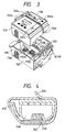
- Fig. 3 is a perspective view for showing a head cartridge 160 housing black and color ink tanks 130 and 140, respectively and integrally holding a recording head (BCHD) for carrying out black and color recordings together.
- the black ink tank 30 has a black triangle mark 206a and a yellow triangle mark 207a provided on the upper surface thereof for the purpose of visual recognition of its presence or absence when the ink tank is mounted on a carriage (not shown). Also, an elastic latch nail 32a is provided on the engaging surface of the ink tank at the time of mounting it on a head cartridge 60. On the side opposite to the side where the elastic latch nail 32a is provided, a dropping off-stopping nail 32d is provided.
- a pop-up spring 68 for pushing up the black ink tank 30, when the black ink tank 30 is detachably mounted and an ink induction portion 70 to be connected with the ink supply opening of the ink tank for supplying ink to the head.
- a reference numeral 130 designates a black ink tank; 140, a color ink tank retaining three kinds of color ink, yellow, magenta, and cyan in it; 132e and 142e, elastic latch nails arranged for each ink tank; 132d and 142d, dropping off-stopping nails; and 206a and 207a, triangle marks, respectively.
- a reference numeral 160 designates the head cartridge that is partitioned by a wall 165 to make it possible to house two ink tanks, and that also is provided with a head (BCHD) capable of discharging ink in each of black, yellow, magenta, and cyan colors, respectively. Further, the head cartridge 160 is provided with pop-up springs 68c (one on the black side is not shown), and with ink induction portions 170b, 170y, 170m, and 170c.
- the head cartridge 160 is provided with pop-up springs 68c (one on the black side is not shown), and with ink induction portions 170b, 170y, 170m, and 170c.
- the method of attachment and detachment made by means of the engaging member or the elastic latch nail mechanism as described above is effective.
- the member itself is structured to be short and comparatively strong against deformation. As a result, there is no need for handling the member with any particular care.
- the ink tank provided with the elastic latch nail is subjected to external shock during its delivery or in a state of being unmounted, because the long arm of the elastic latch nail extends outwardly.
- the elastic latch nail is apt to be damaged or deformed extremely, leading to the incomplete mounting of the ink tank on the head cartridge.
- a hindrance may take place in stabilizing ink supply.
- air bubbles are carried into the interior of the head or, in the worst case, printing becomes disabled. If such damage is very serious, there is a fear that the ink tank becomes unusable.
- a detachably mountable ink tank it is preferable to prevent ink leakage from the ink supply opening of an ink tank during the delivery or in a state of being left unmounted.
- an extremely small ink tank it is should be considered to prevent any ink leakage ideally, because the initial filling of ink is limited to a small quantity, and the ink amount in the ink tank tends to be reduced even by an extremely small amount of splashing of ink into the cap or the like.
- a main object of the present invention is to provide a protection method by means of a simple structure for protecting the above-mentioned elastic latch nail of an ink tank from external shocks.
- another object of the invention is to provide a method and a member for preventing ink leakage from the ink tank and ink splashing onto the interior of the cap, while protecting the elastic latch nail that functions as an attachment and detachment mechanism of a small ink tank, and also to provide an ink tank having the member.
- Still another object of the invention is to provide an ink tank protection method for closing the ink supply opening provided on the bottom face of an ink tank, and holding the elastic latch nail provided on the face adjacent to the bottom face in a state of being substantially fixed, wherein the closing of the ink supply opening and the substantially fixed holding of the elastic latch nail are performed by one and the same means.
- a further object of the invention is to provide an ink tank protection member comprising means for closing the ink supply opening provided on the bottom face of an ink tank, and means for holding the elastic latch nail provided on the face adjacent to the bottom face in a state of being substantially fixed, wherein the means for closing the ink supply opening dually functions as means for holding the elastic latch nail in a state of being substantially fixed.
- Still a further object of the invention is to provide an ink tank protection member comprising means for sealing the communicating groove provided on the upper surface of the ink tank for communicating the interior with the exterior; means for closing the ink supply opening provided on the bottom face of the ink tank; and means for holding the elastic latch nail provided on the face adjacent to the bottom face in a state of being substantially fixed, wherein the means for closing the ink supply opening is structured with the same member functioning as means for sealing the communicating groove, and only the member for sealing the communicating groove is not peeled off when the means for closing the ink supply opening is removed.
- the closing of an ink supply opening and the substantially fixed holding of an elastic latch nail can be performed by one and the same means, and therefore no extra costs are incurred.
- the user can also remove the ink tank protection member easily by one action at the time of using the ink tank.
- the member for fixing the elastic latch nail is provided between the elastic latch nail and the face of the wall of an ink tank, making it possible to protect the elastic latch nail from external shocks.
- a shock relieving material or an absorbent shock relieving member is used for means for closing the ink supply opening. Therefore, it is possible to minimize the amount of ink splashing from the ink supply opening due to external shocks during the delivery of the ink tank or in a state of being left unmounted. In this way, the amount of usable ink is prevented from being reduced. There is also no possibility that the ink tank is stained even when ink splashes.
- Fig. 1 is a perspective view which schematically shows an ink tank conventionally used, and its sealing manner.
- Fig. 2 is a perspective view which shows a head cartridge integrally holding a head (BHD) dedicated to recording in black by housing only a black ink tank.
- BHD head
- Fig. 3 is a perspective view which shows a head cartridge housing a black and color ink tank and integrally holding a head (BCHD) recording in black and color.
- BCHD head
- Fig. 4 is a cross-sectional view which shows one structural example in which the protection of an elastic latch nail and the closing of the ink supply opening of an ink tank are performed simultaneously.
- Figs. 5A to 5C are views showing the other structural examples of the elastic nail and ink tank holding member in accordance with for the first embodiment of the present invention
- Fig. 5A shows a tape for preventing ink leakage provided with a member for fixing an elastic latch nail
- Fig. 5B is a side view of the tape shown in Fig. 5A when it is applied to an ink tank
- Fig. 5C is a perspective view of Fig. 5B.
- Figs. 6A to 6C are views showing still another example of an ink tank protection member; Fig. 6A and Fig. 6B schematically illustrate the ink tank protection member; and Fig. 6C is a side view of the ink tank protection member when it is applied to the ink tank.
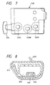
- Fig. 7 is a bottom view of an ink tank for color printing use.
- Fig. 8 is a side view schematically showing, as still another example of an ink tank protection member to which the present invention is applicable, an ink tank protection member having a shock relieving member provided on a portion thereof where it abuts upon the supply opening of the ink tank.
- Figs. 9A and 9B are views showing another example of an ink tank protection member using a capping type shock relieving member; Fig. 9A illustrates the ink tank protection member; Fig. 9B shows a state where an elastic latch fixing member is attached to the ink tank protection member represented in Fig. 9A.
- Figs. 10A and 10B are views showing an ink tank protection member, which is integrated with a sealing member for sealing the atmosphere communicating groove provided on the upper face of the ink tank; Fig. 10A illustrates a state before installation; and Fig. 10B shows a state where the ink tank protection member is applied.
- Fig. 4 is a cross-sectional view for showing one structural example in which the protection of an elastic latch nail and the closing of the supply opening of an ink tank are performed simultaneously.
- a protection tape 220 capable of performing the protection of the elastic latch nail 210 and the closing of the ink supply opening of the ink tank is wound around an ink tank 250.
- a sealing member 240 is provided on the portion of the tape where the sealing tape abuts upon the ink supply opening 230 of the ink tank.
- Figs. 5A to 5C illustrate an elastic latch nail and ink tank protection member in accordance with the present embodiment.
- Fig. 5A shows a tape for preventing ink leakage provided with an elastic latch nail fixing member.
- Fig. 5B is a side view illustrating the tape shown in Fig. 5A in a state that the tape is applied to an ink tank.
- Fig. 5C is a perspective view of Fig. 5B.
- the ink tank protection member shown in Fig. 5A comprises a sealing tape 320 having a tab portion 325 needed for peeling off the sealing tape; and an elastic latch nail fixing member 360 provided on the sealing tape 320 to be nipped between the elastic latch nail 310 of the ink tank and the main body of the ink tank 350 when the sealing tape 320 is applied to the ink tank.
- the ink supply opening (not shown) of the ink tank 350 provided on the bottom face of the ink tank 350 should be closed as illustrated in Figs. 5B and 5C, and then, wind the sealing tape 320 around the ink tank 350 so that the elastic latch nail fixing member 360 is nipped between the elastic latch nail 310 of the ink tank 350 and the main body of the ink tank 350.
- an elastic latch nail fixing member 360 it is preferable to use a solid elastic material, spongy porous material, or the like. Also, in Figs. 5A to 5C, whereas the elastic latch nail fixing member 360 and sealing tape 320 are arranged as separate members to form the ink tank protection member, it is possible to make the ink tank protection member from one elastically deformative material or the like so that the protection member is integratedly formed by a single material and a part of which is nipped between the elastic latch nail and the main body of the ink tank. In this case, it is possible to similary protect the elastic latch nail.
- a sealing member can be provided on the portion where the ink tank protection member closes the supply opening of the ink tank as shown in Fig. 4.
- Figs. 6A to 6C are views for showing one example where an ink tank protection member is formed by a single member: Figs. 6A and 6B illustrate an ink tank protection member; and Fig. 6C is a side view showing a state that the ink tank protection member illustrated in Figs. 6A and 6B is applied to the ink tank.
- the ink tank protection member shown in Figs. 6A to 6C is formed by an elastically deformative member 420.
- the elastically deformative member 420 comprises an elastic latch nail fixing member 460 provided to be nipped between the elastic latch nail 410 of the ink tank and the main body of the ink tank 450 when the elastically deformative member 420 is applied to the ink tank; an ink supply opening sealing member 470 for closing the ink supply opening (not shown) of the ink tank 450; and a pin 480 and a hole 490 for fixing the elastically deformative member 420 to the ink tank 450 by engaging the pin with the hole.
- the ink supply opening of the ink tank arranged on the bottom face of the ink tank 450 should be closed by means of the ink tank supply opening sealing member 470 as shown in Fig. 6C, and then, the elastically deformative member 420 is wound around the ink tank 450 so that the elastic latch nail fixing member 460 is nipped between the elastic latch nail 410 of the ink tank 450 and the main body of the ink tank 450.
- the pin 480 is inserted into the hole 490 to engage them with each other.
- the protection member can be applied easily.
- the upper portion of the pin 480 is fixed by means of a thermal caulking, ultrasonic caulking, or the like. By this, the protection member can be applied easily and reliably. Also, the user can remove the protection member easily just by tearing off the caulked portion.
- the structure of the protection member becomes simpler, and it can have a form that the protection member is peeled off just by one action.
- an ink tank protection member becomes loose or slacken off due to the vibrations given during delivery or environmental changes such as temperature and humidity changes in some cases.
- an ink tank protection method for a ink tank for color printing will be described bellow.
- Fig. 7 is a bottom view of the ink tank for color printing shown in Fig. 2.
- an elastic latch nail 510 is substantially aligned in a line with the ink supply openings 530C, 530M, and 530Y each for different colors, and therefore it is possible to easily apply an ink tank protection member formed by a single member.
- an elongated member such as an adhesive sealing tape or elastically deformative member of such a structure as described above.
- the ink tank for color printing use in which the ink supply openings for the respective colors of the ink tank are substantially aligned in a line with the elastic latch nail, it is possible to prevent ink leakage by use of the ink tank protection member that has been formed by a single member. Also, it is possible to protect the elastic latch nail at the same time. Further, by the structure thus arranged, the user can easily peel off the protection member by one action.
- an ink tank protection member provided with a shock relieving material arranged for the portion where the ink tank protection member faces the ink supply opening of an ink tank.
- Fig. 8 is a view for showing a state where a shock relieving material is provided for the portion of an ink tank protection member facing the ink supply opening of an ink tank.
- the ink tank protection member is provided with a shock relieving member 640 formed by an absorber that performs shock absorption in a position of the sealing tape 620 facing the ink supply opening (not shown) of the ink tank 650, and then, when applying the sealing tape to the ink tank, the ink supply opening of the ink tank 650 is closed by means of the shock relieving member.
- a shock relieving member 640 formed by an absorber that performs shock absorption in a position of the sealing tape 620 facing the ink supply opening (not shown) of the ink tank 650, and then, when applying the sealing tape to the ink tank, the ink supply opening of the ink tank 650 is closed by means of the shock relieving member.
- the shock relieving member 640 absorbs it to minimize the amount of ink splash from the ink tank 650.
- the shock relieving member by forming the shock relieving member with an absorbent, even if an ink should be caused to splash into the capping face due to a strong external shock, the ink is absorbed thereby. Therefore, it is possible to prevent the ink tank from being stained during its delivery or prevent an ink from splashing at the time of removing the sealing member.
- the absorptive shock releiving member it is preferable to use a urethane sponge, elastic unwoven textile, cardboard for use of a corrugated carton, or the like.
- Figs. 9A and 9B illustrate an ink tank protection member using a capping type shock releiving member:
- Fig. 9A is a view showing the ink tank protection member;
- Fig. 9B is a view showing a state that an elastic latch nail fixing member attached to the ink tank protection member represented in Fig. 9A.
- a non-absorptive member is used as a shock releiving member, which is provided with a capping portion whose configuration matches with the ink supply opening of an ink tank. By this member, the ink supply opening is closed so as to prevent ink leakage.
- an elastic material such as elastomer, solid rubber as a non-absorptive member.
- the shock releiving member 740 and the elastic latch nail fixing member 760 may be structured by one and the same material, or these members may be formed separately by different materials as a matter of course if only the materials to be used can satisfy the respective functions.
- an ink tank protection member is formed integrally with a sealing member for sealing an atmosphere communicating groove arranged on the upper surface of an ink tank.
- Figs. 10A and 10B are views showing the ink tank protection member formed together with the sealing member for sealing the atmosphere communicating groove arranged on the upper surface of the ink tank:
- Fig. 10A illustrates a method to be used for the member at the time of being applied; and
- Fig. 10B shows a state where the ink tank protection member is applied to dually performing its function as the elastic latch nail fixing member.
- an atmosphere communicating groove 835 for the ink tank 850 as shown in Fig. 10A in order to prevent ink from being evaporated from an atmosphere communicating orifice portion, and then, in this case, the atmosphere communicating groove 835 is sealed by the sealing member 825 for sealing the atmosphere communicating groove. In this way, it is possible to provide atmosphere communicating means without any ink leakage.
- the sealing member 825 for sealing the atmosphere communicating groove and the sealing tape for use of closing the supply opening of the ink tank by a single member, it is possible to easily manufacture the protection member at a low cost. Also, it is easy for the user to peel off the sealing tape.
- the sealing member 823 for sealing an atmosphere communicating groove is affixed to the upper surface of an atmosphere communicating groove 835 of an ink tank 850 as shown in Fig. 10A, and then, the remaining portion of the sealing tape 820 is wound around the ink tank 850 so as to be affixed thereto. Additionally, for the sealing tape 820, a perforation 821 is provided for the sealing member 823 for sealing the atmosphere communicating groove.
- the tab portion 825 is pulled to gradually peel off the sealed portion as shown in Fig. 10B.
- the perforation 821 is arranged for the sealing tape 820 such that, when the sealing tape 820 is peeled off, the sealing member 823 for sealing the atmosphere communicating groove still remains affixed to the ink tank 850.
- the sealing tape 820 is cut off at the perforation 821, thus allowing the sealing member 823 for sealing the atmosphere communicating groove to remain on the ink tank 850.
- the external opening 835a of the atmosphere communicating groove 835 is sealed, thus making it possible to seal the external opening 835a for sealing the atmosphere communicating and the ink supply opening in good condition, both of them.
- the sealing tape for sealing the atmosphere communicating groove, the sealing tape for sealing the ink supply opening, and the sealing tape for sealing elastic latch nail protection are constituted by means of a single member. Therefore, it is possible to simply manufacture an ink tank protection member at a low cost. Also, it is easy for the user to peel off the tape by one action. Thus the ink tank protection member having good operativity is obtained.
- the description has been made by exemplifying a structure in which no elastic latch nail fixing member is provided for the sealing tape, but the elastic latch nail fixing member may be provided for the tape as a matter of course.
- the closing of the ink supply opening and the substantially fixed holding of the elastic latch nail are performed by one and the same means. Therefore, the processing steps of manufacture can be reduced, making it possible at a low cost to prevent ink leakage from the supply opening of an ink tank and protecting the elastic latch nail from external shocks at the same time.
- the user can also remove the protection member easily by one action at the time of using an ink tank.
- a member for fixing an elastic latch nail is provided between the elastic latch nail and the wall face of an ink tank to thereby protect the elastic latch nail from external shocks, and therefore make it possible to prevent the elastic latch nail from being deformed or damaged.
- an ink tank protection member is sealed over more than four faces of an ink tank, it is possible to effectively prevent the ink tank protection member from becoming loose or slackened due to shocks given during the delivery or the environmental changes such as changes of the temperature and humidity.
- shock releiving member By providing a shock releiving member in the position facing the ink supply opening at the time of applying the ink tank protection member to an ink tank, it is possible to minimize ink splashing from the ink supply opening due to external shocks when the ink tank is delivered or left in a state of being unmounted, hence preventing the reduction of the amount of usable ink available to the user. Since the shock releiving member has a shape almost equal to the configuration of the ink supply opening of an ink tank, it is possible to minimize ink leakage from the ink supply opening.
- the ink tank protection member comprises a sealing tape 320 having a tab portion 325 needed for peeling it off, and an elastic latch nail fixing member 360 provided on the sealing tape to be nipped between the elastic latch nail 310 of the ink tank and the main body of the ink tank 350.
Landscapes
- Ink Jet (AREA)
Applications Claiming Priority (3)
| Application Number | Priority Date | Filing Date | Title |
|---|---|---|---|
| JP4037995 | 1995-02-28 | ||
| JP7040379A JPH08230205A (ja) | 1995-02-28 | 1995-02-28 | インクタンク保護方法及び部材とこれを有するインクタンク |
| JP40379/95 | 1995-02-28 |
Publications (3)
| Publication Number | Publication Date |
|---|---|
| EP0729835A2 true EP0729835A2 (fr) | 1996-09-04 |
| EP0729835A3 EP0729835A3 (fr) | 1998-01-21 |
| EP0729835B1 EP0729835B1 (fr) | 2003-06-18 |
Family
ID=12579028
Family Applications (1)
| Application Number | Title | Priority Date | Filing Date |
|---|---|---|---|
| EP96102917A Expired - Lifetime EP0729835B1 (fr) | 1995-02-28 | 1996-02-27 | Elément et méthode de protection d'un réservoir d'encre |
Country Status (7)
| Country | Link |
|---|---|
| US (1) | US5831652A (fr) |
| EP (1) | EP0729835B1 (fr) |
| JP (1) | JPH08230205A (fr) |
| CN (1) | CN1071195C (fr) |
| AU (1) | AU719013B2 (fr) |
| CA (1) | CA2170339C (fr) |
| DE (1) | DE69628687T2 (fr) |
Cited By (2)
| Publication number | Priority date | Publication date | Assignee | Title |
|---|---|---|---|---|
| GB2350323A (en) * | 1999-01-30 | 2000-11-29 | Dynamic Cassette Int | Ink cartridge with a protruding element which is removable to enable the cartridge to be fully engaged in the printer and open at least one cartridge aperture |
| EP1306218A3 (fr) * | 2001-10-25 | 2003-11-12 | Hewlett-Packard Company | Interconnexion fluidique pour joint d'orifice avec languette de verrouillage |
Families Citing this family (40)
| Publication number | Priority date | Publication date | Assignee | Title |
|---|---|---|---|---|
| DE69511461T2 (de) * | 1994-05-31 | 2000-04-13 | Canon K.K., Tokio/Tokyo | Austauschbare Tintenpatrone mit Verschlussstruktur |
| JP3365215B2 (ja) * | 1996-08-21 | 2003-01-08 | セイコーエプソン株式会社 | プリンタのインクカートリッジ装置 |
| AU139179S (en) * | 1998-10-27 | 1999-12-14 | Canon Kk | Ink tank holder for a printer |
| USD425556S (en) * | 1998-10-27 | 2000-05-23 | Canon Kabushiki Kaisha | Ink tank holder for printer |
| USD425933S (en) * | 1998-10-27 | 2000-05-30 | Canon Kabushiki Kaisha | Ink cartridge for printer |
| JP3667127B2 (ja) | 1998-12-24 | 2005-07-06 | キヤノン株式会社 | 液体供給システムの液体残量検出方法 |
| USD436125S1 (en) | 1999-07-14 | 2001-01-09 | Canon Kabushiki Kaisha | Ink tank for printer |
| USD440599S1 (en) | 1999-07-14 | 2001-04-17 | Canon Kabushiki Kaisha | Ink tank for printer |
| USD436618S1 (en) | 1999-07-14 | 2001-01-23 | Canon Kabushiki Kaisha | Ink tank for printer |
| US6350010B1 (en) | 1999-08-16 | 2002-02-26 | Lexmark International, Inc. | Printer having one or more print cartridges installed during manufacture |
| US6443553B2 (en) | 1999-08-16 | 2002-09-03 | Lexmark International, Inc | Printer having one or more print cartridges installed during manufacture |
| USD441013S1 (en) | 1999-08-27 | 2001-04-24 | Canon Kabushiki Kaisha | Ink tank for ink jet printer |
| AU141690S (en) | 1999-08-27 | 2000-09-04 | Canon Kk | Ink tank for ink jet printer |
| US6502701B2 (en) * | 2000-03-10 | 2003-01-07 | Seiko Epson Corporation | Package for ink cartridge and method for packing cartridge |
| US6481829B1 (en) | 2001-09-18 | 2002-11-19 | Lexmark International, Inc. | Manually actuated carrier latch mechanism |
| JP2003118140A (ja) * | 2001-10-16 | 2003-04-23 | Seiko Epson Corp | インクカートリッジの減圧包装品およびその減圧包装方法 |
| JP3919567B2 (ja) * | 2002-03-18 | 2007-05-30 | キヤノン株式会社 | 液体収納容器の包装構造およびその開封方法 |
| CN100406262C (zh) * | 2002-03-18 | 2008-07-30 | 佳能株式会社 | 液体容器 |
| JP4051248B2 (ja) * | 2002-09-19 | 2008-02-20 | 株式会社リコー | インクカートリッジ包装部材、インクカートリッジ包装体、インクカートリッジの包装・開封方法 |
| USD493194S1 (en) | 2002-09-30 | 2004-07-20 | Canon Kabushiki Kaisha | Printing head for printer |
| US7128409B2 (en) * | 2003-07-31 | 2006-10-31 | Hewlett-Packard Development Company, L.P. | Replaceable printing consumable with features facilitating intuitive installation by a user |
| US7219979B2 (en) * | 2004-02-10 | 2007-05-22 | Lexmark International, Inc. | Inkjet printhead packaging tape for sealing nozzles |
| US20050249519A1 (en) * | 2004-05-06 | 2005-11-10 | Rec & Assign | Cartridge for toner having removable seal |
| US7611222B2 (en) * | 2004-10-06 | 2009-11-03 | Hewlett-Packard Development Company, L.P. | Nozzle shield assembly |
| CN2895063Y (zh) * | 2006-03-24 | 2007-05-02 | 浙江天马电子科技有限公司 | 插入式墨盒 |
| US20090251514A1 (en) * | 2008-04-08 | 2009-10-08 | Static Control Components, Inc. | Universal ink cartridge seal |
| US8579425B2 (en) | 2012-01-27 | 2013-11-12 | Eastman Kodak Company | Seal and secondary film for ink tank |
| US8657426B2 (en) | 2012-01-27 | 2014-02-25 | Eastman Kodak Company | Seal and seal pulling member for ink tank |
| JP6241355B2 (ja) | 2014-04-07 | 2017-12-06 | セイコーエプソン株式会社 | 液体供給ユニット用の保護部材 |
| JP2016107525A (ja) * | 2014-12-08 | 2016-06-20 | セイコーエプソン株式会社 | 保護部材、液体供給ユニットのセット |
| JP6435957B2 (ja) * | 2015-03-27 | 2018-12-12 | ブラザー工業株式会社 | 液体カートリッジ |
| JP2017193105A (ja) | 2016-04-20 | 2017-10-26 | キヤノン株式会社 | 液体収納容器ユニット |
| JP6775992B2 (ja) | 2016-04-22 | 2020-10-28 | キヤノン株式会社 | 液体収容容器および液体吐出装置 |
| US10093105B2 (en) | 2016-04-22 | 2018-10-09 | Canon Kabushiki Kaisha | Liquid storage container and liquid ejection apparatus |
| JP6661462B2 (ja) | 2016-05-16 | 2020-03-11 | キヤノン株式会社 | 液体吐出装置および液体補給容器 |
| JP6746391B2 (ja) | 2016-06-15 | 2020-08-26 | キヤノン株式会社 | 液体収容容器ユニット |
| US10399347B2 (en) | 2016-06-29 | 2019-09-03 | Canon Kabushiki Kaisha | Liquid supplying mechanism, and liquid ejection apparatus |
| CN108001856B (zh) * | 2016-10-28 | 2023-10-27 | 上海艾尔贝包装科技发展有限公司 | 包装装置及其包装方法 |
| JP7199959B2 (ja) | 2018-12-26 | 2023-01-06 | キヤノン株式会社 | 液体吐出装置及び液体吐出装置の制御方法 |
| US12023935B2 (en) | 2022-08-10 | 2024-07-02 | Funai Electric Co., Ltd. | Nozzle sealing tape |
Family Cites Families (11)
| Publication number | Priority date | Publication date | Assignee | Title |
|---|---|---|---|---|
| JPS58194550A (ja) * | 1982-05-10 | 1983-11-12 | Canon Inc | インクカセット |
| JPS6219460A (ja) * | 1985-07-19 | 1987-01-28 | Ricoh Co Ltd | インクカ−トリツジの梱包容器 |
| CA2025561C (fr) * | 1989-09-18 | 1995-07-11 | Seiichiro Karita | Tete d'enregistrement a capuchon |
| EP0424133B1 (fr) * | 1989-10-20 | 1995-03-22 | Canon Kabushiki Kaisha | Cartouche avec réservoir d'encre pouvant être installé dans un appareil à jet d'encre |
| US5148920A (en) * | 1991-03-18 | 1992-09-22 | Zimmer, Inc. | Package and package insert |
| JP3021149B2 (ja) * | 1991-12-19 | 2000-03-15 | キヤノン株式会社 | インクジェット記録手段 |
| US5400060A (en) * | 1992-06-25 | 1995-03-21 | Xerox Corporation | Thermal ink jet cartridge face sealing for shipping |
| JPH06210871A (ja) * | 1993-01-19 | 1994-08-02 | Canon Inc | インクジェット・カートリッジ収納ケース |
| ATE169566T1 (de) * | 1993-05-25 | 1998-08-15 | Canon Kk | Verpackungsbehälter sowie verfahren zu seiner öffnung |
| JP3165281B2 (ja) * | 1993-05-25 | 2001-05-14 | キヤノン株式会社 | 交換型インクジェット記録用インクカートリッジのパッケージおよびその開封方法 |
| JPH06328713A (ja) * | 1993-05-25 | 1994-11-29 | Canon Inc | インクジェット用交換型インクカートリッジ |
-
1995
- 1995-02-28 JP JP7040379A patent/JPH08230205A/ja active Pending
-
1996
- 1996-02-26 US US08/606,947 patent/US5831652A/en not_active Expired - Lifetime
- 1996-02-26 CA CA002170339A patent/CA2170339C/fr not_active Expired - Fee Related
- 1996-02-27 DE DE69628687T patent/DE69628687T2/de not_active Expired - Lifetime
- 1996-02-27 AU AU45770/96A patent/AU719013B2/en not_active Ceased
- 1996-02-27 EP EP96102917A patent/EP0729835B1/fr not_active Expired - Lifetime
- 1996-02-28 CN CN96101283A patent/CN1071195C/zh not_active Expired - Fee Related
Cited By (4)
| Publication number | Priority date | Publication date | Assignee | Title |
|---|---|---|---|---|
| GB2350323A (en) * | 1999-01-30 | 2000-11-29 | Dynamic Cassette Int | Ink cartridge with a protruding element which is removable to enable the cartridge to be fully engaged in the printer and open at least one cartridge aperture |
| GB2350323B (en) * | 1999-01-30 | 2002-12-11 | Dynamic Cassette Int | A cartridge and the combination of a cartridge and a printer |
| AU761941B2 (en) * | 1999-01-30 | 2003-06-12 | Dynamic Cassette International Ltd. | Cartridge having removable part for opening an aperture |
| EP1306218A3 (fr) * | 2001-10-25 | 2003-11-12 | Hewlett-Packard Company | Interconnexion fluidique pour joint d'orifice avec languette de verrouillage |
Also Published As
| Publication number | Publication date |
|---|---|
| AU4577096A (en) | 1996-09-05 |
| CA2170339A1 (fr) | 1996-08-29 |
| EP0729835A3 (fr) | 1998-01-21 |
| US5831652A (en) | 1998-11-03 |
| HK1011651A1 (en) | 1999-07-16 |
| CA2170339C (fr) | 1999-11-23 |
| CN1135970A (zh) | 1996-11-20 |
| EP0729835B1 (fr) | 2003-06-18 |
| CN1071195C (zh) | 2001-09-19 |
| JPH08230205A (ja) | 1996-09-10 |
| DE69628687T2 (de) | 2004-05-13 |
| AU719013B2 (en) | 2000-05-04 |
| DE69628687D1 (de) | 2003-07-24 |
Similar Documents
| Publication | Publication Date | Title |
|---|---|---|
| US5831652A (en) | Member and method for protecting ink tank | |
| EP0761450B1 (fr) | Emballage pour cartouche d'encre et procédé d'emballage | |
| US8172386B2 (en) | Sealing device for fluid reservoir | |
| US6338546B1 (en) | Ink jet head cartridge and ink jet apparatus having same | |
| US6033063A (en) | Ink printer and ink tank with ink spill prevention | |
| KR19980019208A (ko) | 잉크 용기, 이 잉크 용기를 착탈식으로 보유하기 위한 잉크기 홀더 및 잉크 용기 캡(ink container, ink container holder for removably, holding ink container, and ink container cap) | |
| US6241348B1 (en) | Package for ink cartridge and method for manufacturing the same | |
| US6588875B1 (en) | Ink jet cartridge printhead seal | |
| JP2004230705A (ja) | 液体タンク | |
| HK1011651B (en) | Member and method for protecting ink tank | |
| JPH02243351A (ja) | インクカートリッジ | |
| JPH07137274A (ja) | 交換型インクジェット用インクカートリッジ | |
| US6345890B2 (en) | Ink cartridge and ink jet printer | |
| JP3703323B2 (ja) | インクタンクおよびその作製方法 | |
| JP4261819B2 (ja) | インクタンクの包装容器および該包装容器を用いるインクタンク | |
| JP2001347685A (ja) | インクカートリッジ、及びそれに備えられるインク供給口の封止部材 | |
| EP0756937B1 (fr) | Structure de montage pour support de tête d'impression et cartouche d'encre | |
| JPH09174868A (ja) | インクリフィル装置 | |
| EP0723868B1 (fr) | Cadre support d'une cartouche d'encre et kit de remplissage d'encre | |
| JP3359238B2 (ja) | インクジェットカートリッジの保管容器 | |
| JPS60204348A (ja) | 液体噴射記録ヘツドの保護部材 | |
| JPS633961A (ja) | インク供給装置 | |
| US20050029158A1 (en) | Packaging assembly and method | |
| JP3669046B2 (ja) | インクジェットプリンタのインクカートリッジ | |
| KR200391662Y1 (ko) | 잉크출구포트의 덮개 구조 |
Legal Events
| Date | Code | Title | Description |
|---|---|---|---|
| PUAI | Public reference made under article 153(3) epc to a published international application that has entered the european phase |
Free format text: ORIGINAL CODE: 0009012 |
|
| AK | Designated contracting states |
Kind code of ref document: A2 Designated state(s): DE FR GB IT |
|
| PUAL | Search report despatched |
Free format text: ORIGINAL CODE: 0009013 |
|
| AK | Designated contracting states |
Kind code of ref document: A3 Designated state(s): DE FR GB IT |
|
| 17P | Request for examination filed |
Effective date: 19980609 |
|
| 17Q | First examination report despatched |
Effective date: 20000406 |
|
| GRAH | Despatch of communication of intention to grant a patent |
Free format text: ORIGINAL CODE: EPIDOS IGRA |
|
| GRAH | Despatch of communication of intention to grant a patent |
Free format text: ORIGINAL CODE: EPIDOS IGRA |
|
| GRAA | (expected) grant |
Free format text: ORIGINAL CODE: 0009210 |
|
| AK | Designated contracting states |
Designated state(s): DE FR GB IT |
|
| REG | Reference to a national code |
Ref country code: GB Ref legal event code: FG4D |
|
| REF | Corresponds to: |
Ref document number: 69628687 Country of ref document: DE Date of ref document: 20030724 Kind code of ref document: P |
|
| ET | Fr: translation filed | ||
| PLBE | No opposition filed within time limit |
Free format text: ORIGINAL CODE: 0009261 |
|
| STAA | Information on the status of an ep patent application or granted ep patent |
Free format text: STATUS: NO OPPOSITION FILED WITHIN TIME LIMIT |
|
| 26N | No opposition filed |
Effective date: 20040319 |
|
| PGFP | Annual fee paid to national office [announced via postgrant information from national office to epo] |
Ref country code: DE Payment date: 20140228 Year of fee payment: 19 |
|
| PGFP | Annual fee paid to national office [announced via postgrant information from national office to epo] |
Ref country code: FR Payment date: 20140228 Year of fee payment: 19 Ref country code: IT Payment date: 20140204 Year of fee payment: 19 |
|
| PGFP | Annual fee paid to national office [announced via postgrant information from national office to epo] |
Ref country code: GB Payment date: 20140220 Year of fee payment: 19 |
|
| REG | Reference to a national code |
Ref country code: DE Ref legal event code: R119 Ref document number: 69628687 Country of ref document: DE |
|
| GBPC | Gb: european patent ceased through non-payment of renewal fee |
Effective date: 20150227 |
|
| REG | Reference to a national code |
Ref country code: FR Ref legal event code: ST Effective date: 20151030 |
|
| PG25 | Lapsed in a contracting state [announced via postgrant information from national office to epo] |
Ref country code: IT Free format text: LAPSE BECAUSE OF NON-PAYMENT OF DUE FEES Effective date: 20150227 |
|
| PG25 | Lapsed in a contracting state [announced via postgrant information from national office to epo] |
Ref country code: GB Free format text: LAPSE BECAUSE OF NON-PAYMENT OF DUE FEES Effective date: 20150227 Ref country code: DE Free format text: LAPSE BECAUSE OF NON-PAYMENT OF DUE FEES Effective date: 20150901 |
|
| PG25 | Lapsed in a contracting state [announced via postgrant information from national office to epo] |
Ref country code: FR Free format text: LAPSE BECAUSE OF NON-PAYMENT OF DUE FEES Effective date: 20150302 |