EP0732236A2 - Höhenregelungssystem für Kraftfahrzeuge - Google Patents
Höhenregelungssystem für Kraftfahrzeuge Download PDFInfo
- Publication number
- EP0732236A2 EP0732236A2 EP96830111A EP96830111A EP0732236A2 EP 0732236 A2 EP0732236 A2 EP 0732236A2 EP 96830111 A EP96830111 A EP 96830111A EP 96830111 A EP96830111 A EP 96830111A EP 0732236 A2 EP0732236 A2 EP 0732236A2
- Authority
- EP
- European Patent Office
- Prior art keywords
- inclination
- levelling system
- extension elements
- variable extension
- shaft
- Prior art date
- Legal status (The legal status is an assumption and is not a legal conclusion. Google has not performed a legal analysis and makes no representation as to the accuracy of the status listed.)
- Granted
Links
Images


Classifications
-
- B—PERFORMING OPERATIONS; TRANSPORTING
- B60—VEHICLES IN GENERAL
- B60P—VEHICLES ADAPTED FOR LOAD TRANSPORTATION OR TO TRANSPORT, TO CARRY, OR TO COMPRISE SPECIAL LOADS OR OBJECTS
- B60P1/00—Vehicles predominantly for transporting loads and modified to facilitate loading, consolidating the load, or unloading
- B60P1/04—Vehicles predominantly for transporting loads and modified to facilitate loading, consolidating the load, or unloading with a tipping movement of load-transporting element
- B60P1/045—Levelling or stabilising systems for tippers
Definitions
- the present invention relates to a levelling system for motor vehicles, applicable in particular to industrial vehicles with dump bodies.
- a vehicle with a dump body has a frame connected to the wheels via the suspension and an auxiliary frame hinged to the frame at a hinge shaft usually located at the rear end of the vehicle.
- one end of the body When loose material such as soil, sand and so on needs to be dumped, one end of the body is raised until the angle between the body and the frame is sufficient to allow the material to slide off.
- This operation may be carried out with the vehicle stationary but in most cases the vehicle is simultaneously driven forward slowly to facilitate the tipping out of the load.
- the vehicle tilts (and rolls about its longitudinal axis) placing more weight on one side of it than on the other.
- the tilt angle may be just a few degrees at the base, it is much greater at the top when the dump body is raised and leads to irregular dumping.
- the dumping operation is even more critical; such materials, once the vehicle is tilted sideways, tend to come loose mainly on the side opposite the tilted side, thus making the load on the vehicle even more imbalanced by increasing the mass weighing down on one side of the axle.
- the frame and the auxiliary frame must be appropriately constructed but even a strong structure may be insufficient to prevent rolling over or damage in the event of abrupt yielding or subsidence of the ground under the vehicle wheels.
- the aim of the present invention is to overcome the disadvantages mentioned above by providing a levelling system capable of keeping the shaft that hinges the body to the auxiliary frame substantially horizontal so as to allow loaded material to be safely and easily dumped.
- the levelling system disclosed basically includes means for detecting the inclination of the hinge shaft between the dump body and the auxiliary frame to the horizontal and means for adjusting the inclination consisting of a pivoted lever or bracket placed between the supporting structure and the loading structure and operated by at least two variable extension elements on opposite sides of the pivot in accordance with the readings of the detecting means.
- the levelling system disclosed may have an independent control system connected to the existing hydraulic system so as to form a self-contained unit or, in the case of new vehicles, it may be built into the vehicle's hydraulic lift system.
- the invention may be ideally applied to vehicles with dump bodies, be they lorries, semitrailers or trailers.
- the invention may be applied to vehicles with a loading surface, not necessarily a dump body, which is pivoted to an auxiliary frame and which must be kept substantially horizontal.
- a loading surface not necessarily a dump body, which is pivoted to an auxiliary frame and which must be kept substantially horizontal.
- this embodiment applies to so-called long vehicles used for transporting very long or wide loads such as prefabricated girders, to prevent undue torsional stress on the vehicle structures between the portion supported by a tractor and that supported by a trailer.
- the levelling system for motor vehicles is used in particular for vehicles with dump bodies.
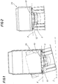
- the invention is applied to a lorry 1 with a supporting frame 3 and an auxiliary frame that hinges to a body 20 at a shaft X placed at one end of the vehicle 1.
- the vehicle has a loading structure, which, in the embodiments illustrated, is defined by the body 20 and a supporting structure (defined by the frame 3 and the auxiliary frame 2) hinged together to permit tipping.
- the system envisages lifting means defined, in the embodiment illustrated, by a pair of hydraulic cylinders 22.
- Fig. 4 shows more clearly the embodiment of the levelling system applied to a lorry with a dump body having its own hydraulic circuit.
- the existing hydraulic circuit activates the cylinders 22 which raise the dump body 20.
- the existing hydraulic circuit includes a pump 83 connected to the power take-off 84 of the vehicle.
- the pump 83 is connected through a suction pipe 94 to a main tank 95 containing the hydraulic oil needed for the operation of the existing hydraulic circuit.
- the pump 83 may be operated by a control lever 88, normally located in the cab 10, in such a way as to activate a control valve 82 (through appropriate pipes 87 and 86) connected to the lift cylinders 22 through a pipe 81 and to the tank 95 through a discharge pipe 90.
- the existing circuit includes a solenoid valve 89 which, as described below, allows a hydraulic controlling circuit of the levelling system disclosed to interact with the existing hydraulic circuit.
- the levelling system includes means 4 for detecting the inclination of the first hinge shaft X to the horizontal and means 5 for adjusting the inclination.
- the inclination detecting means may be an instrument consisting of an inclinometer or similar device, designed to provide an output signal, preferably electrical, in accordance with the detected inclination to the horizontal.
- The-means 5 for adjusting the inclination include at least one lever or bracket 51 placed between the frame 3, the auxiliary frame 2 and the body 20 and centrally pivoted on a substantially horizontal pin perpendicular to the first shaft X so as to define a second shaft Y joining the auxiliary frame 2 and the dump body 20.
- bracket 51 is pivoted to the auxiliary frame 2 supporting the body 20 and connected to the frame 3 through at least two variable extension elements 52s and 52d.
- bracket or lever 51 may be integral with the frame 3 and movable with respect to the auxiliary frame 2.
- variable extension elements 52 are placed opposite each other on both sides of the pin Y and are designed to modify the inclination of the bracket 51 to the frame 3 according to the readings taken by the inclination detecting means 4.
- variable extension elements consist of a pair of hydraulic actuators 52s and 52d (for example, hydraulic cylinders) controlled by a hydraulic circuit.
- the control circuit of the variable extension elements 52 consists of a tank 55 and all the related piping, plus a control unit 93, which is connected at its input at least to the inclination detecting means 4 and at its output to a servovalve 53 connected to the variable extension elements 52, and which is designed to vary the extension of the variable extension elements 52 in accordance with the readings of the inclination detecting means 4.
- the hydraulic control circuit of the variable extension elements 52 is equipped with an electro-hydraulic motor 92.
- the hydraulic control circuit of the variable extension elements 52 is connected through control unit 93 and through the aforementioned servovalve 89 to the inclination detecting means 4 and to the existing control circuit of the cylinders 22.
- the hydraulic control circuit of the variable extension elements 52 may include at least one warning device 96 (which may be a visual warning device as illustrated or an audible warning device or both).
- the warning device 96 is preferably located inside the cab 10 of the vehicle 1 so as to warn the driver when the inclination exceeds a defined angle (stage A).
- the bracket 51 may envisage means for stopping its rotation about the pin Y in such a way as to stop the corresponding rotation of the auxiliary frame 2 about the frame 3.
- the stopping means may be constituted by the variable extension elements 52 themselves, in which case they must be of the type capable of self-locking under defined conditions when not operating.
- they may be constituted by at least one actuator 54 connected to a hydraulic circuit and having at least one end 54' that may be inserted into a corresponding seat made in the bracket 51, or by a vertical plate integral with it.
- the hydraulic control circuit of the variable extension elements 52 may be connected to the inclination detecting means 4 and to a circuit controlling the locks 25 on the sides 24 of the body 20 so as to automatically open the sides 24 when the inclination exceeds a defined angle.
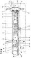
- FIG. 6 shows a possible application where the supporting structure 3 mounts a thrust bearing 30 on which there is a supporting surface 20'. Between the thrust bearing 30 and the supporting surface 20' there is envisaged (either directly or through other connecting structures) a connection that can rotate about a shaft Y placed longitudinally with respect to the vehicle.
- variable extension elements 52 are placed opposite each other on the peripheral portions of the supporting surface 20' so as to keep the load on the supporting surface in a substantially horizontal position.
- This application may be used for thrust bearings which normally allow swinging motion in one direction only: the present invention can be used to make the thrust bearings "active" when they carry structures such as prefabricated girders.
- the system must be mounted on both tractor and trailer.
- the invention described can be subject to modifications and variations without thereby departing from the scope of the inventive concept. Moreover, all the details of the invention may be substituted by technically equivalent elements.
Landscapes
- Engineering & Computer Science (AREA)
- Transportation (AREA)
- Mechanical Engineering (AREA)
- Vehicle Body Suspensions (AREA)
- Body Structure For Vehicles (AREA)
- Control Of Multiple Motors (AREA)
- Soil Working Implements (AREA)
Applications Claiming Priority (3)
| Application Number | Priority Date | Filing Date | Title |
|---|---|---|---|
| IT95BO000106A IT1280224B1 (it) | 1995-03-15 | 1995-03-15 | Sistema di livellamento per autoveicoli |
| ITBO950106 | 1995-03-15 | ||
| US08/652,806 US5769502A (en) | 1995-03-15 | 1996-05-23 | Leveling system for motor vehicles |
Publications (3)
| Publication Number | Publication Date |
|---|---|
| EP0732236A2 true EP0732236A2 (de) | 1996-09-18 |
| EP0732236A3 EP0732236A3 (de) | 1997-03-26 |
| EP0732236B1 EP0732236B1 (de) | 1999-09-22 |
Family
ID=26330323
Family Applications (1)
| Application Number | Title | Priority Date | Filing Date |
|---|---|---|---|
| EP96830111A Expired - Lifetime EP0732236B1 (de) | 1995-03-15 | 1996-03-14 | Höhenregelungssystem für Kraftfahrzeuge |
Country Status (6)
| Country | Link |
|---|---|
| US (1) | US5769502A (de) |
| EP (1) | EP0732236B1 (de) |
| AT (1) | ATE184839T1 (de) |
| DE (1) | DE69604315T2 (de) |
| ES (1) | ES2139324T3 (de) |
| IT (1) | IT1280224B1 (de) |
Cited By (2)
| Publication number | Priority date | Publication date | Assignee | Title |
|---|---|---|---|---|
| EP0830975A1 (de) * | 1996-09-20 | 1998-03-25 | Marco Bettini | Verbessertes Höhenregelungssystem für Kraftfahrzeuge |
| GB2484730A (en) * | 2010-10-22 | 2012-04-25 | Abd Services | Tipper vehicle stabilisation |
Families Citing this family (25)
| Publication number | Priority date | Publication date | Assignee | Title |
|---|---|---|---|---|
| KR100208518B1 (ko) * | 1996-12-10 | 1999-07-15 | 정몽규 | 화물차의 화물평형유지장치 |
| US5997013A (en) * | 1997-07-23 | 1999-12-07 | Upright, Inc. | Chassis stabilization system |
| US5971493A (en) * | 1998-04-10 | 1999-10-26 | Robert; Raymond D. | Automatic dump trailer leveler |
| DE20007311U1 (de) * | 2000-04-20 | 2001-08-30 | Franz Xaver Meiller Fahrzeug- und Maschinenfabrik - GmbH & Co KG, 80997 München | Halterungsanordnung für eine Kipperpresse |
| DE20007795U1 (de) * | 2000-05-04 | 2001-10-11 | Maschinenfabrik Bernard Krone GmbH, 48480 Spelle | Selbstfahrende Erntemaschine, insbesondere Feldhäcksler |
| US20040051260A1 (en) * | 2001-04-09 | 2004-03-18 | Axis Corp | Lifting and leveling apparatus and method |
| US6641161B1 (en) * | 2001-10-19 | 2003-11-04 | Mclelland Gerald R. | Apparatus and method for leveling a trailer bed |
| US7134829B2 (en) * | 2004-03-09 | 2006-11-14 | Absolute Electronic Solutions, Inc. | Cargo trailer |
| PT103110A (pt) * | 2004-04-21 | 2005-10-31 | Vasco Alexandre De Sousa Alves | Maquina transportadora de pessoas e carga |
| US20060006726A1 (en) * | 2004-07-12 | 2006-01-12 | Garvey William R | Height adjustable dumping apparatus |
| US20060239806A1 (en) * | 2005-03-14 | 2006-10-26 | Yelton James E | Mobile material placer and conveying system and method of placing and conveying material utilizing the same |
| US7950675B1 (en) | 2005-05-13 | 2011-05-31 | Absolute Electronic Solutions, Inc. | Cargo carrier |
| DE102006019938B4 (de) * | 2006-04-28 | 2021-02-04 | Franz Xaver Meiller Fahrzeug- Und Maschinenfabrik - Gmbh & Co Kg | Kipperfahrzeug |
| US20080111327A1 (en) * | 2006-11-13 | 2008-05-15 | Rhodes Design And Development Corporation | Transport device capable of adjustment to maintain load planarity |
| US20080173736A1 (en) * | 2007-01-22 | 2008-07-24 | Rexius Forest By-Products, Inc. | High-Speed Material Conveyor Having Direct Hydraulic Drive |
| US8100220B2 (en) | 2008-03-28 | 2012-01-24 | Rexius Forest By-Products, Inc. | Vehicle having auxiliary steering system |
| WO2009158329A2 (en) * | 2008-06-27 | 2009-12-30 | Absolute Electronic Solutions, Inc. | Fifth wheel trailer with adjustable deck |
| US8025340B2 (en) | 2008-08-21 | 2011-09-27 | Foisie Michael R | Bed leveling system for dump truck |
| US8684649B2 (en) * | 2011-06-13 | 2014-04-01 | Johan Redekop | Grain cart |
| CN104965411B (zh) * | 2015-06-12 | 2017-07-25 | 中国电子科技集团公司第三十八研究所 | 一种调平撑腿落地检测阀值的自适应调节方法 |
| US10414318B2 (en) * | 2016-04-28 | 2019-09-17 | Rakkatec Oy | Arrangement for optimizing load position in relation to transportation vehicle |
| CN109398164A (zh) * | 2017-08-18 | 2019-03-01 | 创奕能源科技股份有限公司 | 移动载具用自动位移装置及其控制方法 |
| US11678603B2 (en) * | 2019-05-02 | 2023-06-20 | Bambauer Equipment | Trailered engine driven lagoon pump for Mixing and pumping manure slurries |
| US12409768B2 (en) | 2020-10-26 | 2025-09-09 | Veradyn Llc | Dump trailer and system for a semi-trailer truck |
| US10988067B1 (en) | 2020-10-26 | 2021-04-27 | Veradyn Llc | Dump trailer and system for a semi-trailer truck |
Family Cites Families (9)
| Publication number | Priority date | Publication date | Assignee | Title |
|---|---|---|---|---|
| CH605202A5 (en) * | 1975-09-29 | 1978-09-29 | Langendorf Heinrich Fahrzeugba | Lorry with laterally tilting body |
| US4036528A (en) * | 1975-10-14 | 1977-07-19 | Heinrich Langendorf | Truck with tiltable body |
| DE2652854A1 (de) * | 1976-11-20 | 1978-05-24 | Magirus Deutz Ag | Vorrichtung zum schutz eines fahrzeuges mit kippbarem aufbau gegen umkippen |
| US4261616A (en) * | 1978-12-18 | 1981-04-14 | Beegle William I | Apparatus for preventing the tipping of dump vehicles |
| GB2046957A (en) * | 1979-03-21 | 1980-11-19 | Edbro Holdings | Vehicle stability control system |
| GB2174649B (en) * | 1985-05-08 | 1989-01-25 | Roger Victor Prior | Chassis tilt control for tipper vehicles |
| GB8707237D0 (en) * | 1987-03-26 | 1987-04-29 | Craven Tasker Woodville Ltd | Tipping vehicles |
| JPH0228053A (ja) * | 1988-07-18 | 1990-01-30 | Toshiba Corp | 搬送車 |
| FR2694730B1 (fr) * | 1992-08-17 | 1994-10-28 | Michel Delcroix | Dispositif de commande de sécurité pour véhicule industriel ayant une partie mobile, notamment pour véhicule à benne basculante. |
-
1995
- 1995-03-15 IT IT95BO000106A patent/IT1280224B1/it active IP Right Grant
-
1996
- 1996-03-14 DE DE69604315T patent/DE69604315T2/de not_active Expired - Fee Related
- 1996-03-14 ES ES96830111T patent/ES2139324T3/es not_active Expired - Lifetime
- 1996-03-14 AT AT96830111T patent/ATE184839T1/de not_active IP Right Cessation
- 1996-03-14 EP EP96830111A patent/EP0732236B1/de not_active Expired - Lifetime
- 1996-05-23 US US08/652,806 patent/US5769502A/en not_active Expired - Fee Related
Cited By (4)
| Publication number | Priority date | Publication date | Assignee | Title |
|---|---|---|---|---|
| EP0830975A1 (de) * | 1996-09-20 | 1998-03-25 | Marco Bettini | Verbessertes Höhenregelungssystem für Kraftfahrzeuge |
| US6027173A (en) * | 1996-09-20 | 2000-02-22 | Bettini; Marco | Leveling system for motor vehicles |
| GB2484730A (en) * | 2010-10-22 | 2012-04-25 | Abd Services | Tipper vehicle stabilisation |
| GB2484730B (en) * | 2010-10-22 | 2015-04-29 | Abd Services | Tipper vehicle stabilisation apparatus |
Also Published As
| Publication number | Publication date |
|---|---|
| DE69604315T2 (de) | 2000-05-11 |
| IT1280224B1 (it) | 1998-01-05 |
| ES2139324T3 (es) | 2000-02-01 |
| EP0732236B1 (de) | 1999-09-22 |
| ITBO950106A1 (it) | 1996-09-15 |
| ITBO950106A0 (it) | 1995-03-15 |
| US5769502A (en) | 1998-06-23 |
| ATE184839T1 (de) | 1999-10-15 |
| DE69604315D1 (de) | 1999-10-28 |
| EP0732236A3 (de) | 1997-03-26 |
Similar Documents
| Publication | Publication Date | Title |
|---|---|---|
| EP0732236B1 (de) | Höhenregelungssystem für Kraftfahrzeuge | |
| US5971493A (en) | Automatic dump trailer leveler | |
| US6027173A (en) | Leveling system for motor vehicles | |
| AU2010214533B2 (en) | Transporter vehicle | |
| US5813697A (en) | Forklift stabilizing apparatus | |
| US6688836B2 (en) | Self-propelled dolly with power lift | |
| EP1855914B1 (de) | Verfahren und anordnung zum verhindern des umkippens eines kippfahrzeugs | |
| US4036528A (en) | Truck with tiltable body | |
| US4536009A (en) | Vehicle stabilizing system | |
| EP1556555B1 (de) | Kompaktlader | |
| USRE39477E1 (en) | Forklift stabilizing apparatus | |
| JPH08268137A (ja) | ダンプ車両の横転防止装置 | |
| KR20140013634A (ko) | 덤프트럭의 전복 방지 장치 | |
| KR20180077669A (ko) | 덤프트럭의 데크 제어장치 및 제어방법 | |
| JP2005125983A (ja) | 軌陸車の転車台装置 | |
| GB2202497A (en) | Tipping vehicles, and their stabilisation | |
| CN1167056A (zh) | 机动车辆的调平系统 | |
| JPH1151753A (ja) | 荷重検出装置及びその検出方法 | |
| GB2484730A (en) | Tipper vehicle stabilisation | |
| JPS59252Y2 (ja) | クレ−ン付トラツク | |
| KR0152403B1 (ko) | 휠로더의 버켓보조 상승장치 | |
| IE55131B1 (en) | Automobile vehicle for towing and for hoisting loads | |
| JP2004345855A (ja) | 作業車両 | |
| KR20220157306A (ko) | 자동으로 가변축 균형을 조절할 수 있는 화물 차량용 자동 가변축 조절시스템 | |
| JP2603179Y2 (ja) | ダンプ式粉粒体運搬車 |
Legal Events
| Date | Code | Title | Description |
|---|---|---|---|
| PUAI | Public reference made under article 153(3) epc to a published international application that has entered the european phase |
Free format text: ORIGINAL CODE: 0009012 |
|
| AK | Designated contracting states |
Kind code of ref document: A2 Designated state(s): AT BE CH DE DK ES FR GB IT LI NL SE |
|
| PUAL | Search report despatched |
Free format text: ORIGINAL CODE: 0009013 |
|
| AK | Designated contracting states |
Kind code of ref document: A3 Designated state(s): AT BE CH DE DK ES FR GB IT LI NL SE |
|
| 17P | Request for examination filed |
Effective date: 19970617 |
|
| 17Q | First examination report despatched |
Effective date: 19980121 |
|
| GRAG | Despatch of communication of intention to grant |
Free format text: ORIGINAL CODE: EPIDOS AGRA |
|
| GRAG | Despatch of communication of intention to grant |
Free format text: ORIGINAL CODE: EPIDOS AGRA |
|
| GRAH | Despatch of communication of intention to grant a patent |
Free format text: ORIGINAL CODE: EPIDOS IGRA |
|
| GRAH | Despatch of communication of intention to grant a patent |
Free format text: ORIGINAL CODE: EPIDOS IGRA |
|
| GRAA | (expected) grant |
Free format text: ORIGINAL CODE: 0009210 |
|
| AK | Designated contracting states |
Kind code of ref document: B1 Designated state(s): AT BE CH DE DK ES FR GB IT LI NL SE |
|
| PG25 | Lapsed in a contracting state [announced via postgrant information from national office to epo] |
Ref country code: SE Free format text: THE PATENT HAS BEEN ANNULLED BY A DECISION OF A NATIONAL AUTHORITY Effective date: 19990922 Ref country code: NL Free format text: LAPSE BECAUSE OF FAILURE TO SUBMIT A TRANSLATION OF THE DESCRIPTION OR TO PAY THE FEE WITHIN THE PRESCRIBED TIME-LIMIT Effective date: 19990922 Ref country code: LI Free format text: LAPSE BECAUSE OF FAILURE TO SUBMIT A TRANSLATION OF THE DESCRIPTION OR TO PAY THE FEE WITHIN THE PRESCRIBED TIME-LIMIT Effective date: 19990922 Ref country code: CH Free format text: LAPSE BECAUSE OF FAILURE TO SUBMIT A TRANSLATION OF THE DESCRIPTION OR TO PAY THE FEE WITHIN THE PRESCRIBED TIME-LIMIT Effective date: 19990922 Ref country code: BE Free format text: LAPSE BECAUSE OF FAILURE TO SUBMIT A TRANSLATION OF THE DESCRIPTION OR TO PAY THE FEE WITHIN THE PRESCRIBED TIME-LIMIT Effective date: 19990922 Ref country code: AT Free format text: LAPSE BECAUSE OF FAILURE TO SUBMIT A TRANSLATION OF THE DESCRIPTION OR TO PAY THE FEE WITHIN THE PRESCRIBED TIME-LIMIT Effective date: 19990922 |
|
| REF | Corresponds to: |
Ref document number: 184839 Country of ref document: AT Date of ref document: 19991015 Kind code of ref document: T |
|
| REG | Reference to a national code |
Ref country code: CH Ref legal event code: EP |
|
| REF | Corresponds to: |
Ref document number: 69604315 Country of ref document: DE Date of ref document: 19991028 |
|
| ITF | It: translation for a ep patent filed | ||
| PG25 | Lapsed in a contracting state [announced via postgrant information from national office to epo] |
Ref country code: DK Free format text: LAPSE BECAUSE OF FAILURE TO SUBMIT A TRANSLATION OF THE DESCRIPTION OR TO PAY THE FEE WITHIN THE PRESCRIBED TIME-LIMIT Effective date: 19991222 |
|
| ET | Fr: translation filed | ||
| REG | Reference to a national code |
Ref country code: ES Ref legal event code: FG2A Ref document number: 2139324 Country of ref document: ES Kind code of ref document: T3 |
|
| NLV1 | Nl: lapsed or annulled due to failure to fulfill the requirements of art. 29p and 29m of the patents act | ||
| REG | Reference to a national code |
Ref country code: CH Ref legal event code: PL |
|
| PLBE | No opposition filed within time limit |
Free format text: ORIGINAL CODE: 0009261 |
|
| STAA | Information on the status of an ep patent application or granted ep patent |
Free format text: STATUS: NO OPPOSITION FILED WITHIN TIME LIMIT |
|
| 26N | No opposition filed | ||
| REG | Reference to a national code |
Ref country code: GB Ref legal event code: IF02 |
|
| PGFP | Annual fee paid to national office [announced via postgrant information from national office to epo] |
Ref country code: FR Payment date: 20020312 Year of fee payment: 7 |
|
| PGFP | Annual fee paid to national office [announced via postgrant information from national office to epo] |
Ref country code: GB Payment date: 20020313 Year of fee payment: 7 |
|
| PGFP | Annual fee paid to national office [announced via postgrant information from national office to epo] |
Ref country code: ES Payment date: 20020321 Year of fee payment: 7 |
|
| PGFP | Annual fee paid to national office [announced via postgrant information from national office to epo] |
Ref country code: DE Payment date: 20020327 Year of fee payment: 7 |
|
| PG25 | Lapsed in a contracting state [announced via postgrant information from national office to epo] |
Ref country code: GB Free format text: LAPSE BECAUSE OF NON-PAYMENT OF DUE FEES Effective date: 20030314 |
|
| PG25 | Lapsed in a contracting state [announced via postgrant information from national office to epo] |
Ref country code: ES Free format text: LAPSE BECAUSE OF NON-PAYMENT OF DUE FEES Effective date: 20030315 |
|
| PG25 | Lapsed in a contracting state [announced via postgrant information from national office to epo] |
Ref country code: DE Free format text: LAPSE BECAUSE OF NON-PAYMENT OF DUE FEES Effective date: 20031001 |
|
| GBPC | Gb: european patent ceased through non-payment of renewal fee |
Effective date: 20030314 |
|
| PG25 | Lapsed in a contracting state [announced via postgrant information from national office to epo] |
Ref country code: FR Free format text: LAPSE BECAUSE OF NON-PAYMENT OF DUE FEES Effective date: 20031127 |
|
| REG | Reference to a national code |
Ref country code: FR Ref legal event code: ST |
|
| REG | Reference to a national code |
Ref country code: ES Ref legal event code: FD2A Effective date: 20030315 |
|
| PG25 | Lapsed in a contracting state [announced via postgrant information from national office to epo] |
Ref country code: IT Free format text: LAPSE BECAUSE OF NON-PAYMENT OF DUE FEES Effective date: 20050314 |