EP0734100A2 - Connecteur électrique avec une position finale assurée - Google Patents
Connecteur électrique avec une position finale assurée Download PDFInfo
- Publication number
- EP0734100A2 EP0734100A2 EP96103644A EP96103644A EP0734100A2 EP 0734100 A2 EP0734100 A2 EP 0734100A2 EP 96103644 A EP96103644 A EP 96103644A EP 96103644 A EP96103644 A EP 96103644A EP 0734100 A2 EP0734100 A2 EP 0734100A2
- Authority
- EP
- European Patent Office
- Prior art keywords
- connector
- slide
- base unit
- plug
- housing
- Prior art date
- Legal status (The legal status is an assumption and is not a legal conclusion. Google has not performed a legal analysis and makes no representation as to the accuracy of the status listed.)
- Granted
Links
Images





Classifications
-
- H—ELECTRICITY
- H01—ELECTRIC ELEMENTS
- H01R—ELECTRICALLY-CONDUCTIVE CONNECTIONS; STRUCTURAL ASSOCIATIONS OF A PLURALITY OF MUTUALLY-INSULATED ELECTRICAL CONNECTING ELEMENTS; COUPLING DEVICES; CURRENT COLLECTORS
- H01R13/00—Details of coupling devices of the kinds covered by groups H01R12/70 or H01R24/00 - H01R33/00
- H01R13/62—Means for facilitating engagement or disengagement of coupling parts or for holding them in engagement
- H01R13/639—Additional means for holding or locking coupling parts together, after engagement, e.g. separate keylock, retainer strap
-
- H—ELECTRICITY
- H01—ELECTRIC ELEMENTS
- H01R—ELECTRICALLY-CONDUCTIVE CONNECTIONS; STRUCTURAL ASSOCIATIONS OF A PLURALITY OF MUTUALLY-INSULATED ELECTRICAL CONNECTING ELEMENTS; COUPLING DEVICES; CURRENT COLLECTORS
- H01R13/00—Details of coupling devices of the kinds covered by groups H01R12/70 or H01R24/00 - H01R33/00
- H01R13/62—Means for facilitating engagement or disengagement of coupling parts or for holding them in engagement
- H01R13/627—Snap or like fastening
- H01R13/6271—Latching means integral with the housing
-
- H—ELECTRICITY
- H01—ELECTRIC ELEMENTS
- H01R—ELECTRICALLY-CONDUCTIVE CONNECTIONS; STRUCTURAL ASSOCIATIONS OF A PLURALITY OF MUTUALLY-INSULATED ELECTRICAL CONNECTING ELEMENTS; COUPLING DEVICES; CURRENT COLLECTORS
- H01R13/00—Details of coupling devices of the kinds covered by groups H01R12/70 or H01R24/00 - H01R33/00
- H01R13/66—Structural association with built-in electrical component
- H01R13/70—Structural association with built-in electrical component with built-in switch
- H01R13/703—Structural association with built-in electrical component with built-in switch operated by engagement or disengagement of coupling parts, e.g. dual-continuity coupling part
Definitions
- the present invention relates to electrical connectors, and in particular the electrical connector used at the base unit initiator (SQUIB) in a inflatable (airbag) restraint system incorporated into contemporary vehicles.
- SQUIB base unit initiator
- airbag inflatable restraint system
- the initiators of the inflatable restraint systems must be interconnected with a controller that will provide the signal necessary to activate the initiator when required.
- the interconnection at the initiator must be sufficiently robust that the interconnection is maintained in a reliable manner.
- the interconnection must be one that is simple and easy to install due to the large number of vehicles incorporating interconnections of this type where the installation may typically occur along a manufacturing assembly line process.
- US Patent 5,314,345 discloses an electrical connection system particularly suited for the application described above.
- the initiator carries a pair of male connector elements that are to be releasably mated with a pair of female connector elements carried by an electrical connector component.
- a shorting clip is associated with the initiator for providing an electrical short between the male connector elements, as is common in these application, whereby an inadvertent potential may not be established across the elements.
- the shorting clip is displaceable out of the shorting position when the connector is mated therewith.
- the connector includes a housing and a perpendicularly extending plug for receiving the male pins where resilient latch means for providing an mechanical latch with the initiator are spaced from and extend along the plug.
- a separate locking element is provided which is insertable into a locked position between the latch and plug when the initiator and connector are mated for preventing disengagement therebetween.
- the locking element is preferably tethered to the connector and may be placed into an opening to maintain the resilient latches inforced engagement with the initiator.
- United States Patent No. 5,275,575 the locking element is further used to defeat the short circuit after the connector is mated with the base unit of the initiator.
- EP-A-0 632 534 also describes a connector suited for the application described above.
- the electrical connector described includes a connector housing having a plug extending therefrom for mating with the initiator and resilient latch arms on either side thereof and extending therealong in a spaced manner.
- the resilient latch arm engages a complementary recess in the initiator.
- a slidable cover that is displaceable between first and second positions includes blocking elements which are movable transversely into the space between the plug and the resilient arms to prevent disengagement with the initiator.
- the sliding cover includes the blocking elements which results in a complex moulding.
- the geometrical confines of having a transversely movable locking element extending from the cover make it difficult to manufacture a robust assembly that provides the support necessary along the resilient arms.
- the blocking elements become jammed as a result of some debris or foreign material obstructing the mechanism.
- an object of the present invention to provide an electrical connector for interconnecting with a base unit that is of compact construction, is releasably interconnected to the base unit, and includes means to assure that the connector is reliably held respective to the base unit.
- an electrical connector terminatable to a conductive pathway for interconnection thereof to conductors within a base unit
- the connector comprising a housing having a body portion for receiving interconnection elements therein, a plug extending outward from the body and being receivable by the base unit, and a retention member extending outward from the body and being receivable by a retention feature in the base unit to retain the connector therewith; a slide movable along the body between a first position and a second position; and a support element responsive to the slide and including extensions that are clear of the retention member in the first position for mating and demating of the connector in the base and wherein the second position the support element supports the retention member to prevent demating therebetween
- the connector characterized in that the extensions are displaceable axially along the retention member in the direction the retention member extends from the body between the first and second positions.
- the electrical connector according to the present invention is compact and of economical construction. It is another advantage that the extensions used to support the retention member are displaceable axially therealong in response to displacement of the slide. It is yet another advantage of the present invention that the extensions may be disposed between a plug and the retention members, whereby they are protected from damage.
- switch means for disabling the air bag actuating circuit so long as the slide remains in its first position and for enabling the circuit when the slide has been moved to its second position in which the connector is locked to the base unit.
- a warning lamp on the dash board of the vehicle may be arranged to be illuminated when the circuit is disabled so that the vehicle cannot exit a production line without indication that the connector has not been locked to the base unit.
- the air bag actuating circuit may be disabled in the first position of the slide by means of a short-circuiting link bridging the conductors of the base unit, the connector having means for displacing the short circuiting link from the conductors when the slide is moved to its second position.
- the slide may be provided with a contact for short circuiting the terminals until the slide has been moved to its second position.
- Leads for connecting the terminals to the sensors may be passed through bores in a ferrite filter bead before being connected to the terminals and the bead lodged in the housing.
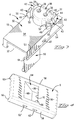
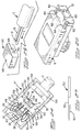
- an electrical connector according to a first embodiment of the invention, which is generally referenced 2, comprises an insulating housing 4 with a displaceable insulating slide 6 thereon.
- the slide 6 has therein a support element 8 (best seen in Figure 5) which is responsive to relative movement between the slide 6 and the housing 4 and which is also made of an insulating material.
- the connector 2 terminates insulated electrical leads 10 and 12, of a jacketed cable C.
- a base unit generally referenced 14 comprises a body portion 16 defining a socket 18.
- a socket 18 Within the socket 18 is a pair of conductors in the form of pins 20 connected to, for example, an air bag igniter of the kind generally known as a squib of an air bag actuating circuit to sensors of which the leads 10 and 12 are connected.
- the socket 18 has a plug receiving region 22, above in which is a retention feature 24, in the present embodiment, a circular section cylindrical groove undercut relative to the plug receiving region 22. Above the retention feature 24 the socket has an outwardly flared lead in mouth 26.
- the socket 18 may have a key 28 in the mouth 26 for correct orientation of the mating connector 2 with respect to the conductors 20.
- the housing 4 has a body portion 30 having an underside 34 from which depends a plug 36 for mating with the socket 18.
- a pair of openings 38 for receiving the conductors 20 of the socket 18 and providing access to socket contacts 39 of electrical terminals 41 (Figure 11) located in grooves 33 in the open interior 32 of the housing 4.
- retention members 42 which in this embodiment are resiliently deflectable arms 46 formed integrally with the body portion 30 of the housing 4.
- the arms 46 have latch heads 44 at their ends remote from the underside 34.
- Each latch head 44 has a leading camming surface 48 and a retention shoulder 50 spaced back therefrom.
- openings 51 There are defined between the retention members 42 and the plug 36, openings 51.
- the ribs 63 assure that the lid 59 can only be seated on the housing if the terminals 41 are correctly located in their grooves 33, as may not occur for example, if the terminals have been bent.
- the ribs 63 may be replaced, for example, by a single rib 63', shown in broken lines in Figure 11, which extends transversely of the length of the housing 4.
- the slide 6 has an upper wall 56 and side walls 58 provided with gibs 60 which provide slide tracks for receiving the respective rails 54 and 57, thereby enabling the slide 6 to be displaced along the housing 4 between a first and a second position as will be described below.
- the first and second positions are established by means of pairs of latching openings 62 and 62' in the side walls 58, each pair of which cooperates with a single latching boss 67 on each side wall 53 and 55 of the housing 4.
- An opening 64 extending through the upper wall 56 of the slide 6 has generally upstanding opposed side walls 66 and first and second opposed camming surfaces 68 and 70, for a purpose described below.
- the support element 8 comprises a head 72 with upstanding opposed side walls 74 which are spaced apart for sliding reception in the opening 64 of the slide 6 between the side walls 66.
- the side walls 74 are interconnected by first and second camming surfaces 76 and 78, respectively, which correspond to the first and second camming surfaces 68 and 70, respectively, of the slide 6.
- the surfaces 74, 76 and 78 are interconnected at their upper ends, by a top surface 80 and at their lower ends by a base 82. There depend from opposite sides of the base 82, respective support extensions 84. Each extension 84 has an arcuate inner surface 86 corresponding to the curvature of the plug 36 of the housing 4. Each extension 84 also has an arcuate outer surface 88 corresponding to the curvature of the inner surfaces of the latch members 42 of the housing 4. Each support extension 84 has a free end 90.
- the functioning of the electrical connector 2 will now be described with particular reference to Figures 6 to 12.
- the terminals 41 having been assembled to the housing 4 and the lid 59 flipped to its closed position, the slide 6 is mounted on the housing 4 and the support element 8 is positioned in the opening 64 of the slide 6 so that the camming surfaces 68 and 76 face each other, and the camming surfaces 70 and 78 also face each other.
- the top surface 80 thereof lies substantially flush with the upper wall 56 of the slide 6.
- the element 8 may be made in a contrasting colour to that of the slide 6 to provide a visual indication that the support element 8 is in its first position.
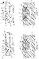
- Figure 7 shows the plug 36 mated with the socket 18 of the base unit 14.
- a respective retention member 42 is shown with its latch head 44 received within the retention feature 24 of the socket 18.
- the connector 2 can be unmated from the socket 18 by withdrawing the connector 2 in the direction of the arrow B in Figure 7, the retention member 42 being free to deflect into the adjacent opening 51.
- the respective extension 84 of the support element 8 is in a raised position relative to the latch head 44. In this first position of the support element 8, the plug 36 can be either mated or unmated with the socket 18.
- the slide 6 In order to locate the slide 6, and thus the support element 8, in their first positions, the slide 6 is applied to the housing 4 in the direction of the arrow C in Figure 11 so that the rearmost latching openings 62' of the side walls 58 of the slide 6 are latchingly engaged by the respective bosses 67 on the side walls of the housing 4.
- the slide 6 and the element 8 can be moved to their second positions ( Figures 8 and 9) by advancing the slide 6 in the direction of the arrow D in Figure 8 so that the latching openings 62 of the slide 6 are latchingly engaged in by the bosses 67 of the housing 4.
- each extension 84 is displaced downwardly into the respective opening 51 so as to protrude behind the respective latch head 44 thereby preventing displacement thereof, so that the connector cannot be withdrawn from the socket 18.
- the air bag actuating circuit cannot be inadvertently disabled, that is to say the circuit between the crash sensors of the vehicle, connected to the leads 10 and 12, and the conductors 20 of the base unit 14 which are connected to the air bag igniter.
- the lid 59 ensures that the circuit is not deactivated as a result of faulty positioning of the terminals 41.
- the lid 59 be formed integrally with the housing 4, the lid may alternatively be provided as a separate item, as will be described below.
- the housing 4 contains a first terminal 41, and a second terminal 100 comprising two parts 102 and 104, respectively.
- the part 102 comprises a resilient switch arm 103 as best seen in Figure 15 for connection to a respective conductor 20 of the socket 18.
- the part 104 acts as the fixed contact of the switch so provided.
- the upper wall 56' of the slide is formed with an obliquely inwardly projecting switch actuating ramp 106 which is forwardly inclined.
- the switch arm 103 When the slide is in its first position, the switch arm 103 is displaced from the fixed contact part 104 so that the air bag actuating circuit is broken.
- the ramp 106 drives the switch arm 103 of the terminal 100 against the fixed part 104 so that the air bag actuating circuit is made.
- the switch provided by the parts 102 and 104 When the switch provided by the parts 102 and 104 is in the broken condition, it may be arranged that a warning lamp on the dash board of the vehicle is illuminated.
- one of the terminals comprises two rectilinear parts 108 and 110, respectively, which lie in the same plane, the top wall 56'' of the slide having a bridge contact 112 fixed thereto.
- the bridge contact 112 engages only the portion 108 of the terminal.
- the bridge contact 112 bridges the portions 108 and 110 of the terminal.
- the contact 112 comprises a pair of spaced bights 114 and 116 respectively, one for engaging each of the terminal portions 108 and 110 in the second position of the slide.
- the slide may have a contact (not shown) for short circuiting the terminals until the slide is moved to its second position.
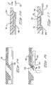
- the support element 8' has a short-circuiting link displacement leg 120 depending from the base 82 between the support extensions 84 and being slidable along a flat front face 122 of the plug 36'.
- the leg 120 is of rectangular cross section.
- the socket 18' of the base unit contains an insulating moulding 124 secured in the socket by means of latches 126 engaged in recesses 128 in the moulding 124.
- a spring metal short-circuiting link 130 having a pair of spring contact arms 132 normally projected across the socket 18' and each engaging a respective one of the conductors 20, as shown in Figure 23, and thereby short-circuiting the conductors 20 and thus disabling the air bag actuating circuit.
- the leg 120 of the support element 8' is in a raised position ( Figure 21) as are the support extensions 84 of the element 8'.
- the extensions 84 are moved down to lock the plug in its mating relationship with the socket as described above, and the leg 120 is moved down between the spring arms 132 of the link 130, and the front face 122 of the plug, thereby displacing the spring arms 132 from the conductors 20 ( Figure 22) and thus disabling the link 130 and enabling the air bag actuating circuit.
- the actuating circuit cannot, therefore, be enabled until the connector has been locked to the base unit.
- a warning lamp may be arranged to be illuminated on the dash board of the vehicle while the conductors 20 are short-circuited, as an indication that the actuating circuit is disabled.
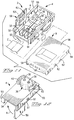
- the housing 4'' contains a ferrite filter bead 140 which is located in the open interior of the housing by means of a pair of flanges 142 projecting inwardly from the upper margins of the side walls of the housing 4'' and a key 144 extending from a rib 143 between the terminals 41' and engaging in a recess 146 in the bead 140 which has through bores 148 through which the leads 10 and 12 extending from the cable C pass.
- the terminals 41' have slotted plate (IDC) contacts 150 into which the end portions of the leads have been forced. Each terminal is received in a groove 33' and has a forked contact end 39' for engaging about a respective conductor 20. The terminals are downwardly bent into the grooves at 149.
- the slide rails 54' extend along the full length of the housing on each side thereof, as do flat ledges 151 for receiving a loose piece lid 153 (Figure 27) held in position longitudinally of the housing by means of opposed shoulders 154 and 156.
- the lid 153 has a reduced cross section portion 155 with a terminal position assurance rib 157.
- the free end portions of the leads 10 and 12 are first inserted through the bores 148 of the bead 140 as indicated by the arrow E in Figure 25 and the bead is inserted into the housing.
- the ends of the leads, which project from the bores 148 are then forced into the slots of the contacts 150 of the terminals, which have been secured in the grooves and a metal strain relief sleeve 152 is crimped about the cable C.
- a loose piece lid 160 is secured on the housing by means of lateral stepped recesses 162 in the upper margins of the side walls of the housing, into which recesses lateral margins 164 of the lid 160 are fitted.
- the lid 160 has a transverse terminal position assurance rib 166, shown in broken lines, on its underside.
Landscapes
- Details Of Connecting Devices For Male And Female Coupling (AREA)
Applications Claiming Priority (4)
| Application Number | Priority Date | Filing Date | Title |
|---|---|---|---|
| GB9505697 | 1995-03-20 | ||
| GBGB9505697.4A GB9505697D0 (en) | 1995-03-21 | 1995-03-21 | Electrical connector having retention assurance |
| GBGB9508743.3A GB9508743D0 (en) | 1995-04-28 | 1995-04-28 | Electrical connector with terminal position assurance |
| GB9508743 | 1995-04-28 |
Publications (3)
| Publication Number | Publication Date |
|---|---|
| EP0734100A2 true EP0734100A2 (fr) | 1996-09-25 |
| EP0734100A3 EP0734100A3 (fr) | 1997-09-24 |
| EP0734100B1 EP0734100B1 (fr) | 2003-05-07 |
Family
ID=26306718
Family Applications (1)
| Application Number | Title | Priority Date | Filing Date |
|---|---|---|---|
| EP96103644A Expired - Lifetime EP0734100B1 (fr) | 1995-03-20 | 1996-03-08 | Connecteur électrique avec une position finale assurée |
Country Status (3)
| Country | Link |
|---|---|
| US (1) | US5647757A (fr) |
| EP (1) | EP0734100B1 (fr) |
| DE (1) | DE69627923T2 (fr) |
Cited By (21)
| Publication number | Priority date | Publication date | Assignee | Title |
|---|---|---|---|---|
| WO1997041623A1 (fr) * | 1996-04-30 | 1997-11-06 | Framatome Connectors International | Connecteur pourvu d'un blocage auxiliaire et d'une sortie laterale de cable |
| FR2783102A1 (fr) * | 1998-09-05 | 2000-03-10 | Amphenol Tuchel Elect | Connecteur electrique |
| EP1115181A1 (fr) * | 2000-01-07 | 2001-07-11 | Sumitomo Wiring Systems, Ltd. | Connecteur électrique |
| DE10025296A1 (de) * | 2000-05-22 | 2001-12-06 | Fci Automotive Deutschland Gmb | Steckverbinder, insbesondere für Airbag-Zündsysteme |
| EP1137115A3 (fr) * | 2000-01-25 | 2002-04-10 | AMPHENOL-TUCHEL ELECTRONICS GmbH | Prise électrique |
| EP1253680A1 (fr) * | 2001-04-26 | 2002-10-30 | J.S.T. Mfg. Co., Ltd. | Ensemble de connection électrique comportant un verouillage |
| EP1605555A1 (fr) * | 2004-06-07 | 2005-12-14 | Delphi Technologies, Inc. | Connecteur électrique |
| EP1708312A1 (fr) * | 2005-04-02 | 2006-10-04 | AMPHENOL-TUCHEL ELECTRONICS GmbH | Connecteur électrique pour un système de retenue dans un véhicule |
| US7121867B2 (en) | 2005-01-13 | 2006-10-17 | Amphenol-Tuchel Electronics Gmbh | Electrical pin-and-socket connector |
| EP1855358A1 (fr) * | 1997-07-03 | 2007-11-14 | Fci | Connecteur enfichable extra plat |
| EP1361629B1 (fr) * | 2002-05-07 | 2008-06-04 | J.S.T. Mfg. Co., Ltd. | Connecteur électrique |
| EP2020706A2 (fr) | 2007-08-01 | 2009-02-04 | Sumitomo Wiring Systems, Ltd. | Connecteur, assemblage de connecteur et procédé de connexion |
| EP3121909A1 (fr) * | 2015-07-21 | 2017-01-25 | Delphi Technologies, Inc. | Connecteur électrique à impédance réglée |
| CN107482390A (zh) * | 2017-08-14 | 2017-12-15 | 苏州玛斯堡威电子科技有限公司 | 一种电力插接供电装置 |
| CN108242687A (zh) * | 2017-08-14 | 2018-07-03 | 舒海球 | 一种新型的新能源汽车装置 |
| CN108242702A (zh) * | 2017-08-14 | 2018-07-03 | 舒丽燕 | 一种新型电力插接供电装置 |
| CN108242701A (zh) * | 2017-08-14 | 2018-07-03 | 舒丽燕 | 一种改进型电力插接供电装置 |
| CN108242622A (zh) * | 2017-08-14 | 2018-07-03 | 舒海球 | 一种实用的新能源汽车装置 |
| WO2018213660A1 (fr) * | 2017-05-19 | 2018-11-22 | Gentex Corporation | Connecteur à profil bas avec contacts à ressort |
| CN114465058A (zh) * | 2020-11-03 | 2022-05-10 | 现代自动车株式会社 | 连接器组件及其制造方法 |
| US12658646B2 (en) | 2022-05-09 | 2026-06-16 | Te Connectivity Solutions Gmbh | Electrical connector for a safety restraint system and a testing method thereof |
Families Citing this family (33)
| Publication number | Priority date | Publication date | Assignee | Title |
|---|---|---|---|---|
| US5924885A (en) * | 1997-07-10 | 1999-07-20 | Framatome Connectors Interlock, Inc. | Axial connection with position assurance system |
| DE69822740T2 (de) * | 1997-09-09 | 2005-02-10 | Sumitomo Wiring Systems, Ltd., Yokkaichi | Verbinder |
| DE19804599C2 (de) * | 1998-02-06 | 2001-03-08 | Amphenol Tuchel Elect | Elektrischer Steckverbinder |
| SE9802054L (sv) * | 1998-06-10 | 1999-12-11 | Marcus Andersson | Anordning vid en mobiltelefonhållare |
| US6663411B2 (en) * | 1998-07-15 | 2003-12-16 | Tyco Electronics Logistics Ag | Clamshell connector for airbag gas generator |
| DE19840726C2 (de) * | 1998-09-07 | 2000-09-28 | Amphenol Tuchel Elect | Elektrischer Steckverbinder |
| DE19845351C1 (de) * | 1998-10-02 | 2000-02-24 | Amphenol Tuchel Elect | Elektrischer Steckverbinder |
| US6157350A (en) * | 1999-10-07 | 2000-12-05 | Motorola, Inc. | Antenna latching mechanism |
| JP3508016B2 (ja) * | 1999-12-24 | 2004-03-22 | 住友電装株式会社 | コネクタ |
| USD456776S1 (en) | 2001-01-23 | 2002-05-07 | Datex - Ohmeda, Inc. | Snap sensor connector |
| US6533601B2 (en) * | 2001-02-09 | 2003-03-18 | Tyco Electronics Corporation | Electrical connector assembly with a laterally deflectable latch member and CPA |
| JP2002319459A (ja) * | 2001-04-20 | 2002-10-31 | Jst Mfg Co Ltd | スクイブ用コネクタおよびその部品 |
| JP2003142208A (ja) * | 2001-11-07 | 2003-05-16 | Sumitomo Wiring Syst Ltd | コネクタ |
| JP2003203722A (ja) * | 2001-12-31 | 2003-07-18 | Jst Mfg Co Ltd | 電気コネクタ用プラグ及びその組み立て方法 |
| JP2003249308A (ja) * | 2002-02-25 | 2003-09-05 | Tyco Electronics Amp Kk | 電気コネクタ組立体 |
| JP4084079B2 (ja) * | 2002-05-07 | 2008-04-30 | 日本圧着端子製造株式会社 | コネクタ構造 |
| US20040192098A1 (en) * | 2002-06-28 | 2004-09-30 | Slobodan Pavlovic | Electrical connector with spring back/self rejection feature |
| US6792997B2 (en) * | 2002-08-07 | 2004-09-21 | Rmg Industries, Inc. | Device for securing a string ladder to the bottom rail of a horizontal blind assembly |
| US8405500B2 (en) * | 2004-11-10 | 2013-03-26 | Caterpillar Inc. | System and method for power and data delivery on a machine |
| US20100207744A1 (en) * | 2004-11-10 | 2010-08-19 | Caterpillar Inc. | System And Method For Power And Data Delivery On A Machine |
| US7423547B2 (en) * | 2005-09-29 | 2008-09-09 | Lear Corporation | System and method for verifying assembly of manufactured parts using RFID tags |
| US20070114846A1 (en) * | 2005-11-23 | 2007-05-24 | Slobadan Pavlovic | Power supply circuit for removable automotive interior systems with integrated position sensor system |
| US20070141903A1 (en) * | 2005-12-19 | 2007-06-21 | Casperson Paul G | Electrical connector assembly |
| JP2008140571A (ja) * | 2006-11-30 | 2008-06-19 | Sumitomo Wiring Syst Ltd | コネクタ |
| DE102009001079B4 (de) | 2009-02-23 | 2022-02-03 | Te Connectivity Germany Gmbh | Steckverbinderkörper, elektrischer Steckverbinder sowie Verfahren zum Montieren eines elektrischen Kabels in einem Steckverbinder |
| EP2583052B1 (fr) * | 2010-06-18 | 2016-11-16 | Battelle Memorial Institute | Détonateur à base de matériaux non énergétiques |
| ITMO20130071A1 (it) * | 2013-03-18 | 2014-09-19 | Meta System Spa | Connettore per il collegamento alla diagnostica di bordo di un veicolo |
| US9356394B2 (en) | 2013-12-11 | 2016-05-31 | JAE Oregon, Inc. | Self-rejecting connector |
| US8968021B1 (en) | 2013-12-11 | 2015-03-03 | JAE Oregon, Inc. | Self-rejecting automotive harness connector |
| DE102014219030B4 (de) * | 2014-09-22 | 2016-07-07 | Robert Bosch Gmbh | Steckermodul |
| CN105545710B (zh) * | 2016-01-28 | 2018-11-20 | 珠海格力电器股份有限公司 | 驱动器盒及家用电器 |
| US10910743B2 (en) | 2018-11-06 | 2021-02-02 | Lear Corporation | Electrical assembly and method |
| TWI673918B (zh) * | 2018-12-03 | 2019-10-01 | 宣德科技股份有限公司 | 電連接器 |
Family Cites Families (21)
| Publication number | Priority date | Publication date | Assignee | Title |
|---|---|---|---|---|
| US3639890A (en) * | 1970-06-09 | 1972-02-01 | Bendix Corp | Locking connector assembly |
| US3683314A (en) * | 1971-01-21 | 1972-08-08 | Bunker Ramo | Cable junction box |
| DE2633590C2 (de) * | 1976-07-27 | 1984-09-27 | Daimler-Benz Ag, 7000 Stuttgart | Zündvorrichtung für ein passives Rückhaltesystem |
| JPS559301A (en) * | 1978-07-01 | 1980-01-23 | Nissan Motor | Connector for igniter |
| US4435742A (en) * | 1980-01-31 | 1984-03-06 | Ford Motor Company | Electrochemical transistor structure with two spaced electrochemical cells |
| JPS6071084U (ja) * | 1983-10-24 | 1985-05-20 | 星電器製造株式会社 | ロツク機構付コネクタ |
| US4634204A (en) * | 1985-12-24 | 1987-01-06 | General Motors Corporation | Electrical connector with connector position assurance/assist device |
| DE3619288A1 (de) * | 1986-06-07 | 1987-12-23 | Stocko Metallwarenfab Henkels | Elektrische steckverbindung |
| US4786258A (en) * | 1987-05-13 | 1988-11-22 | Amp Incorporated | Electrical connector with shunt |
| US4929189A (en) * | 1988-04-13 | 1990-05-29 | Hosiden Electronics Co., Ltd. | Connector with locking mechanism |
| JPH0773068B2 (ja) * | 1988-08-05 | 1995-08-02 | 英朗 茂治 | ロック機構付きコネクター |
| US4915642A (en) * | 1989-01-19 | 1990-04-10 | Pan-International Industrial Corporation | Trouble-free connector with lock mechanism |
| US4971568A (en) * | 1989-12-11 | 1990-11-20 | Polaroid Corporation | Electrical connector with attachment for automatically shorting select conductors upon disconnection of connector |
| DE4217205C2 (de) * | 1992-05-23 | 1994-09-08 | Amphenol Tuchel Elect | Steckverbinder |
| US5275575A (en) * | 1992-10-09 | 1994-01-04 | Trw Inc. | Electrical connection system with safety interlock |
| US5314345A (en) * | 1992-10-09 | 1994-05-24 | Trw Inc. | Electrical connection system with interlock |
| JPH06325832A (ja) * | 1993-05-12 | 1994-11-25 | Sumitomo Wiring Syst Ltd | コネクタ |
| DE4317344A1 (de) * | 1993-05-25 | 1994-12-01 | Framatome Connectors Int | Elektrischer Steckverbinder |
| JPH0747913A (ja) * | 1993-05-31 | 1995-02-21 | Nippon Seiko Kk | エアバッグ装置のインフレータ用導線接続装置 |
| US5401180A (en) * | 1993-06-01 | 1995-03-28 | Itt Corporation | Connector shorting spring |
| EP0650229A3 (fr) * | 1993-10-22 | 1997-01-02 | Amphenol Tuchel Elect | Système de sécurité à sac gonflable. |
-
1996
- 1996-03-08 EP EP96103644A patent/EP0734100B1/fr not_active Expired - Lifetime
- 1996-03-08 DE DE69627923T patent/DE69627923T2/de not_active Expired - Fee Related
- 1996-03-18 US US08/617,229 patent/US5647757A/en not_active Expired - Fee Related
Cited By (31)
| Publication number | Priority date | Publication date | Assignee | Title |
|---|---|---|---|---|
| WO1997041623A1 (fr) * | 1996-04-30 | 1997-11-06 | Framatome Connectors International | Connecteur pourvu d'un blocage auxiliaire et d'une sortie laterale de cable |
| US6341972B1 (en) | 1996-04-30 | 2002-01-29 | Framatome Connectors International | Connector with secondary latching and with a lateral cable outlet |
| EP1855358A1 (fr) * | 1997-07-03 | 2007-11-14 | Fci | Connecteur enfichable extra plat |
| FR2783102A1 (fr) * | 1998-09-05 | 2000-03-10 | Amphenol Tuchel Elect | Connecteur electrique |
| EP1115181A1 (fr) * | 2000-01-07 | 2001-07-11 | Sumitomo Wiring Systems, Ltd. | Connecteur électrique |
| US6439914B2 (en) | 2000-01-07 | 2002-08-27 | Sumitomo Wiring Systems, Ltd. | Connector having a short-circuiting element |
| EP1137115A3 (fr) * | 2000-01-25 | 2002-04-10 | AMPHENOL-TUCHEL ELECTRONICS GmbH | Prise électrique |
| DE10025296A1 (de) * | 2000-05-22 | 2001-12-06 | Fci Automotive Deutschland Gmb | Steckverbinder, insbesondere für Airbag-Zündsysteme |
| DE10025296C2 (de) * | 2000-05-22 | 2003-03-20 | Fci Automotive Deutschland Gmb | Steckverbinder, insbesondere für Airbag-Zündsysteme |
| US6663413B2 (en) | 2000-05-22 | 2003-12-16 | Framatome Connectors International | Connector, particularly for airbag ignition systems |
| US6699059B2 (en) | 2001-04-26 | 2004-03-02 | J.S.T. Mfg., Co., Ltd. | Electrical connector assembly comprising locking part |
| EP1253680A1 (fr) * | 2001-04-26 | 2002-10-30 | J.S.T. Mfg. Co., Ltd. | Ensemble de connection électrique comportant un verouillage |
| EP1361629B1 (fr) * | 2002-05-07 | 2008-06-04 | J.S.T. Mfg. Co., Ltd. | Connecteur électrique |
| EP1605555A1 (fr) * | 2004-06-07 | 2005-12-14 | Delphi Technologies, Inc. | Connecteur électrique |
| US7121867B2 (en) | 2005-01-13 | 2006-10-17 | Amphenol-Tuchel Electronics Gmbh | Electrical pin-and-socket connector |
| US7229305B2 (en) | 2005-04-02 | 2007-06-12 | Amphenol-Tuchel Electronics Gmbh | Electrical pin-and-socket connector for vehicle retention systems |
| EP1708312A1 (fr) * | 2005-04-02 | 2006-10-04 | AMPHENOL-TUCHEL ELECTRONICS GmbH | Connecteur électrique pour un système de retenue dans un véhicule |
| EP2020706A2 (fr) | 2007-08-01 | 2009-02-04 | Sumitomo Wiring Systems, Ltd. | Connecteur, assemblage de connecteur et procédé de connexion |
| EP2020706A3 (fr) * | 2007-08-01 | 2009-02-11 | Sumitomo Wiring Systems, Ltd. | Connecteur, assemblage de connecteur et procédé de connexion |
| EP3121909A1 (fr) * | 2015-07-21 | 2017-01-25 | Delphi Technologies, Inc. | Connecteur électrique à impédance réglée |
| US9787031B2 (en) | 2015-07-21 | 2017-10-10 | Delphi Technologies, Inc. | Electrical connector with adjusted impedance |
| WO2018213660A1 (fr) * | 2017-05-19 | 2018-11-22 | Gentex Corporation | Connecteur à profil bas avec contacts à ressort |
| US10971830B2 (en) | 2017-05-19 | 2021-04-06 | Gentex Corporation | Low profile connector with spring contacts |
| US10490914B2 (en) | 2017-05-19 | 2019-11-26 | Gentex Corporation | Low profile connector with spring contacts |
| CN108242687A (zh) * | 2017-08-14 | 2018-07-03 | 舒海球 | 一种新型的新能源汽车装置 |
| CN108242622A (zh) * | 2017-08-14 | 2018-07-03 | 舒海球 | 一种实用的新能源汽车装置 |
| CN108242701A (zh) * | 2017-08-14 | 2018-07-03 | 舒丽燕 | 一种改进型电力插接供电装置 |
| CN108242702A (zh) * | 2017-08-14 | 2018-07-03 | 舒丽燕 | 一种新型电力插接供电装置 |
| CN107482390A (zh) * | 2017-08-14 | 2017-12-15 | 苏州玛斯堡威电子科技有限公司 | 一种电力插接供电装置 |
| CN114465058A (zh) * | 2020-11-03 | 2022-05-10 | 现代自动车株式会社 | 连接器组件及其制造方法 |
| US12658646B2 (en) | 2022-05-09 | 2026-06-16 | Te Connectivity Solutions Gmbh | Electrical connector for a safety restraint system and a testing method thereof |
Also Published As
| Publication number | Publication date |
|---|---|
| DE69627923D1 (de) | 2003-06-12 |
| DE69627923T2 (de) | 2004-03-11 |
| US5647757A (en) | 1997-07-15 |
| EP0734100B1 (fr) | 2003-05-07 |
| EP0734100A3 (fr) | 1997-09-24 |
Similar Documents
| Publication | Publication Date | Title |
|---|---|---|
| US5647757A (en) | Electrical connector with terminal position assurance | |
| EP1588456B1 (fr) | Connecteur electrique presentant un element d'assurance de position de connecteur | |
| CA2519472C (fr) | Connecteur electrique comprenant un organe qui garantit la position du connecteur | |
| EP1054481B1 (fr) | Un connecteur | |
| KR100278818B1 (ko) | 안전 연동장치를 구비한 전기 접속 시스템 | |
| US5145356A (en) | Electrical connector housings | |
| EP1662621B1 (fr) | Connecteur electrique | |
| EP0921600B1 (fr) | Ensemble connecteur d'amorce exempt d'orientation pour ensembles airbag d'automobiles | |
| US6203342B1 (en) | Grounding plate for orientationless squib connector assembly for automotive air bag assemblies | |
| US5586902A (en) | Electric connector | |
| US4894019A (en) | Torsion spring shorting connector | |
| US5820399A (en) | Connector fitting construction | |
| US4978311A (en) | Electrical connector having connector-operable shorting bar | |
| KR100219361B1 (ko) | 맞물림검출장치를 갖는 커넥터 | |
| US5749747A (en) | Partial-fitting prevention connector | |
| US5924885A (en) | Axial connection with position assurance system | |
| US10236640B2 (en) | Electrical connector for a safety restraint system | |
| JPH0738311B2 (ja) | 電気コネクタ | |
| KR100216000B1 (ko) | 스위치를갖는전기커넥터조립체 | |
| KR200303347Y1 (ko) | 단락 전기 커넥터 | |
| EP0624929B1 (fr) | Connecteur avec le contact à circuit court | |
| EP0657968B1 (fr) | Connecteur à détection de verrouillage | |
| US6422894B1 (en) | Connector fitting detection construction | |
| EP1225659B1 (fr) | Dispositif de connexion électrique | |
| JPH0467582A (ja) | 低挿抜力電気コネクタ |
Legal Events
| Date | Code | Title | Description |
|---|---|---|---|
| PUAI | Public reference made under article 153(3) epc to a published international application that has entered the european phase |
Free format text: ORIGINAL CODE: 0009012 |
|
| AK | Designated contracting states |
Kind code of ref document: A2 Designated state(s): DE FR GB IT |
|
| PUAL | Search report despatched |
Free format text: ORIGINAL CODE: 0009013 |
|
| AK | Designated contracting states |
Kind code of ref document: A3 Designated state(s): DE FR GB IT |
|
| 17P | Request for examination filed |
Effective date: 19980311 |
|
| 17Q | First examination report despatched |
Effective date: 20010307 |
|
| GRAH | Despatch of communication of intention to grant a patent |
Free format text: ORIGINAL CODE: EPIDOS IGRA |
|
| GRAH | Despatch of communication of intention to grant a patent |
Free format text: ORIGINAL CODE: EPIDOS IGRA |
|
| GRAA | (expected) grant |
Free format text: ORIGINAL CODE: 0009210 |
|
| AK | Designated contracting states |
Designated state(s): DE FR GB IT |
|
| PG25 | Lapsed in a contracting state [announced via postgrant information from national office to epo] |
Ref country code: IT Free format text: LAPSE BECAUSE OF FAILURE TO SUBMIT A TRANSLATION OF THE DESCRIPTION OR TO PAY THE FEE WITHIN THE PRE;WARNING: LAPSES OF ITALIAN PATENTS WITH EFFECTIVE DATE BEFORE 2007 MAY HAVE OCCURRED AT ANY TIME BEFORE 2007. THE CORRECT EFFECTIVE DATE MAY BE DIFFERENT FROM THE ONE RECORDED.SCRIBED TIME-LIMIT Effective date: 20030507 Ref country code: FR Free format text: LAPSE BECAUSE OF FAILURE TO SUBMIT A TRANSLATION OF THE DESCRIPTION OR TO PAY THE FEE WITHIN THE PRESCRIBED TIME-LIMIT Effective date: 20030507 |
|
| REG | Reference to a national code |
Ref country code: GB Ref legal event code: FG4D |
|
| REF | Corresponds to: |
Ref document number: 69627923 Country of ref document: DE Date of ref document: 20030612 Kind code of ref document: P |
|
| PG25 | Lapsed in a contracting state [announced via postgrant information from national office to epo] |
Ref country code: GB Free format text: LAPSE BECAUSE OF NON-PAYMENT OF DUE FEES Effective date: 20040308 |
|
| PLBE | No opposition filed within time limit |
Free format text: ORIGINAL CODE: 0009261 |
|
| STAA | Information on the status of an ep patent application or granted ep patent |
Free format text: STATUS: NO OPPOSITION FILED WITHIN TIME LIMIT |
|
| 26N | No opposition filed |
Effective date: 20040210 |
|
| EN | Fr: translation not filed | ||
| GBPC | Gb: european patent ceased through non-payment of renewal fee | ||
| PGFP | Annual fee paid to national office [announced via postgrant information from national office to epo] |
Ref country code: DE Payment date: 20080430 Year of fee payment: 13 |
|
| PG25 | Lapsed in a contracting state [announced via postgrant information from national office to epo] |
Ref country code: DE Free format text: LAPSE BECAUSE OF NON-PAYMENT OF DUE FEES Effective date: 20091001 |