EP0735190B1 - Verfahren zum Schrauben und Losschrauben der Schienenschrauben eines Gleises und Vorrichtung zur Durchführung des Verfahrens - Google Patents
Verfahren zum Schrauben und Losschrauben der Schienenschrauben eines Gleises und Vorrichtung zur Durchführung des Verfahrens Download PDFInfo
- Publication number
- EP0735190B1 EP0735190B1 EP95810200A EP95810200A EP0735190B1 EP 0735190 B1 EP0735190 B1 EP 0735190B1 EP 95810200 A EP95810200 A EP 95810200A EP 95810200 A EP95810200 A EP 95810200A EP 0735190 B1 EP0735190 B1 EP 0735190B1
- Authority
- EP
- European Patent Office
- Prior art keywords
- tie
- tie screw
- head
- respect
- screw
- Prior art date
- Legal status (The legal status is an assumption and is not a legal conclusion. Google has not performed a legal analysis and makes no representation as to the accuracy of the status listed.)
- Expired - Lifetime
Links
- 238000000034 method Methods 0.000 title claims description 19
- 230000008569 process Effects 0.000 title claims description 10
- 241001669679 Eleotris Species 0.000 title description 2
- 238000001514 detection method Methods 0.000 claims description 5
- 230000005693 optoelectronics Effects 0.000 claims description 3
- 238000005259 measurement Methods 0.000 claims description 2
- 230000000903 blocking effect Effects 0.000 claims 1
- 238000006073 displacement reaction Methods 0.000 abstract description 8
- 230000003287 optical effect Effects 0.000 abstract 2
- 238000005096 rolling process Methods 0.000 abstract 1
- 230000033001 locomotion Effects 0.000 description 6
- 238000010586 diagram Methods 0.000 description 2
- 230000000977 initiatory effect Effects 0.000 description 2
- 238000009434 installation Methods 0.000 description 2
- 230000008878 coupling Effects 0.000 description 1
- 238000010168 coupling process Methods 0.000 description 1
- 238000005859 coupling reaction Methods 0.000 description 1
- 238000005336 cracking Methods 0.000 description 1
- 230000006872 improvement Effects 0.000 description 1
- 230000009467 reduction Effects 0.000 description 1
- 230000003252 repetitive effect Effects 0.000 description 1
- 239000000725 suspension Substances 0.000 description 1
- 230000000007 visual effect Effects 0.000 description 1
Images


Classifications
-
- E—FIXED CONSTRUCTIONS
- E01—CONSTRUCTION OF ROADS, RAILWAYS, OR BRIDGES
- E01B—PERMANENT WAY; PERMANENT-WAY TOOLS; MACHINES FOR MAKING RAILWAYS OF ALL KINDS
- E01B29/00—Laying, rebuilding, or taking-up tracks; Tools or machines therefor
- E01B29/24—Fixing or removing detachable fastening means or accessories thereof; Pre-assembling track components by detachable fastening means
- E01B29/28—Fixing or removing detachable fastening means or accessories thereof; Pre-assembling track components by detachable fastening means the fastening means being of screw-and-nut type; Apparatus therefor, adapted to additionally drilling holes
Definitions
- the present invention relates to a method of screwing and unscrewing the lag bolts of a railroad track according to which a carriage advancing on the track and carrying lag bolt detection devices and threading heads is used, as well as a machine for setting of the process.
- FR-A-2 682 135 and FR-A-2 666 358 have proposed machines operated by a single operator.
- the machines described in these documents have two double drawing heads to act simultaneously on the four bolts of a cross member, a double head acting by rail file.
- document FR-A-2 682 135 the four heads are lowered simultaneously, after their positioning relative to the four lag bolts, the detection of the nuts being carried out by mechanical feelers.
- Document FR-A-2 666 358 provides for the individual descent of each of the heads and also the possibility that a beam supporting the double heads can pivot relative to an axis perpendicular to the plane of the track to be placed parallel to an oblique cross. There is no provision for prior detection of the nuts other than that made visually by the operator.
- the installation of the dowel heads and the initiation of operations are carried out by an operator behind the two double dowel heads.
- Document FR-A 2 072 853 presents a machine for carrying out railway work.
- a process for screwing and unscrewing lag screws of a railroad is implemented by this machine which comprises a vehicle advancing on the track and supporting threading heads and bolt detection devices.
- the object of the present invention is to propose a method and a machine making it possible to remedy the drawbacks of the prior art and to ensure high quality work at a high rate.
- the different measured positions are recorded progressively to allow an improvement in the working rate of the carriage. So, it is not necessary to wait for the end of a work cycle to measure the positions of the lag screws which will be treated later.
- the invention also relates to a machine for implementing the method according to the invention.
- the machine comprises a carriage provided with means for moving on the track, means for detecting and determining the relative position of a lag screw with respect to a drawing head, of a module per line of rails equipped with at least one dowel head, said module being arranged to be able to be moved relative to the carriage in the direction of the axis of the rail queue, said dowel head being provided with means to be moved relative to the module in a first direction parallel to the axis of the rail line, in a second direction perpendicular to this axis and parallel to the cross-member, in a third direction perpendicular to the plane defined by the two previous directions, and angularly with respect to this third direction, and automatic means individually initiating a drawing cycle for each head.
- the depositor obtained a rate of 400 meters per hour.
- Figure 1 is a schematic side view of the carriage.
- Figure 2 is a partial cross-sectional view of a rail on a cross member.
- Figure 3 is a plan view of a rail on sleepers.
- FIG. 4 is a side view of a carriage more detailed than FIG. 1.
- Figure 5 is a cross-sectional view showing a double dowel head in the working position.
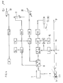
- Figure 6 is a block diagram of a device for controlling the positioning of each dowel head.
- the carriage 1 shown in Figure 1 is provided with a drawbar 2 by which it is connected to a machine ensuring locomotion of the carriage.
- the carriage moves on the rail 3 fixed to the crosspieces 4 by means of lag screws 5, 26.
- the carriage 1 could be provided with autonomous displacement means.
- the carriage 1 is provided with a group 6 ensuring the supply of energy, both hydraulic and electric.
- An optoelectronic device 7 for detecting and measuring the position of the lag bolts is arranged on the front part of the carriage. In principle, such a device per line of rails is used.
- the device 7 is connected to a box 8 for storing and processing all the electronic data.
- An encoder 9 disposed at the rear end of the carriage gives the position X 0 of the carriage at all times on the rail 3.
- the carriage 1 is provided on its upper part with a horizontal rod 11 secured to the carriage 1 on which a module slides 10 provided on its lower part with two rollers 12 ensuring its guiding with respect to the rail 3.
- the module 10 is moved along an axis X parallel to the axis of the rail by a jack 13 controlled by a servovalve 14.
- the position X M of the module 10 with respect to the carriage 1 is indicated by a linear potentiometer 15.
- the module 10 carries two drawing heads 16, 16a of which only one is visible in FIG. 1. Each head is provided with a jack 17 actuated by a valve 18 for raising and lowering the dowel head.
- a linear encoder 19 makes it possible to know the height of the head at any time.
- a double-acting cylinder 20 supplied by a valve 21 ensures the transverse displacement of the head 16 by sliding it on transverse guides 22.
- An encoder 23 makes it possible to measure the transverse displacement of the head (Fig. 3).
- the module is provided at its lower part with two clamps 24 actuated by jacks 25 (Fig. 4).
- the clamps make it possible to immobilize the module relative to the rail 3 so that the head 16 can unscrew the lag screw.
- the device 7 is an optoelectronic device, for example a CCD camera (for Charge Coupling Device) with high resolution.
- a CCD camera for Charge Coupling Device
- Such a camera is, in principle, used for each row of rails. Indeed, the image captured by this camera is divided into two parts, namely one part by lag screw. The position of each lag screw is thus captured in an XY plane (see definition below), which makes it possible to guide each bolt head individually.
- the carriage 1 is also equipped with a module 10 provided with two drawing heads 16 and 16a.
- the head 16a is shown in the high position and it is identical to the head 16. It is mounted on two guide columns 27 secured to a sheath 28 sliding on a guide rod 29.
- a jack 30 controlled by a valve not shown acts on a reference 31 formed by a triangular plate one of the vertices of which is secured to the end of the jack 30, another vertex is secured to a rod 27a secured to one of the guide columns 27 and the third provided with a encoder 32 is articulated around an axis 31a integral with the module 10.
- the heads 16 and 16a are independent of each other concerning the direction of movement along three orthogonal axes X, Y, Z inside of course the module 10.
- a jack 33 (FIG. 5) allows by its extension the inclination of the head by pivoting around the rod guide 29.
- Figure 5 there is shown the drawing head 16 in a position perpendicular to the cross member 4, that is to say corresponding to an angle ⁇ equal to 0 °. This angle could vary up to approximately 5 ° by the sole extension of the jack 33.
- the potentiometer 15 in FIG. 1 enabling the displacement of the module 10 to be known has been replaced in FIG. 4 by a rotary encoder 34 driven by a belt 35, the two ends of which are fixed on two anterior and posterior faces of the module 10, in particular at points 10a and 10b.
- Three return rollers 34a, 34b, 34c ensure the movement of this toothed belt during the movement of the module 10 inside the carriage.
- each drawing head 16 comprises a hydraulic motor 16b with incorporated reduction gear, a counter 16c for the number of revolutions and a key 16d.
- the detector 7 captures and stores the exact position of each lag screw in the XY plane of an orthogonal reference base XYZ defined as follows:
- X is an axis parallel to the axis of the rail 3 and located on the top of the rail
- Y is an axis perpendicular to the previous one and parallel to the cross-member, located on the internal side of the rail, Z being perpendicular to the plane defined by the two other axes.
- the bolt coordinates are the pairs X 1i Y 1i , X 2i Y 2i , X 3i Y 3i , X 4i Y 4i .
- the computer calculates the differences ⁇ X, ⁇ Y between the positions of the lag bolts and those of the corresponding heads along the two axes X and Y.
- the slave jacks 13, 20 and 30 bring each of the heads above the lag screws to be treated, for example the lag screw 26. In other words, the heads move until the differences ⁇ X, ⁇ Y are zero.
- the jack 25 then closes the clamp 24 to immobilize the module 10 and the cycle of each drawing head begins, namely: the descent to the lag screw, the screwing and the ascent. Subsequently the module 10 is released by loosening the clamp 24 and it moves in the direction of the lag bolts of the next crosspiece.
- X i + 1 X 0 (i + 1) + X D etc.
- the value of the angle ⁇ is preset on the basis of visual observations prior to the work or in accordance with the data established during the installation of the track. However, if for one reason or another, one of the lag bolts has been pressed with an angle which differs from the preset angle ⁇ , when the tool 16d tries to grasp the head of the lag bolt, an auto-adjustment of the angle ⁇ is produced around the preset position so that the tool 16d can grasp the lag screw without destroying it.
- a lag screw 5 arranged on a line of rails 3 and whose absolute coordinates are X i , Y i , Z i .
- the device 7 makes it possible to know the coordinates detected X D , Y D , Z D.
- the potentiometer 15 indicates the position longitudinal X M of the carriage, which makes it possible to calculate the absolute position of the carriage X M + X 0 and to calculate the difference ⁇ X i .
- ⁇ X i is the distance that the carriage 1 must travel for the head to be positioned above the lag screw 5 and which corresponds to a signal SV X to be sent to the solenoid valve of the jack 13 and possibly 30 to ensure the movement along X of the module.
- the value Y D is transmitted to a computer which makes it possible to calculate the difference ⁇ Y i taking account of the position Y M of the module which is known since it is always the same. It is thus possible to send a signal SV y corresponding to ⁇ Y i to the solenoid valve of the double-acting cylinder 20 to position the head of the lag screw along the Y axis.
- the position Z D of the module which is also constant makes it possible to calculate the value ⁇ Z i which corresponds to a signal SV Z to be sent to the solenoid valve of the jack 17 allowing the head to be lowered to the height of the lag screw 5. Finally, if necessary , the angle ⁇ is introduced into a device, which makes it possible to send a signal EV ⁇ to the solenoid valve of the piston 33 to control the angular displacement of the drawing head.
Landscapes
- Engineering & Computer Science (AREA)
- Architecture (AREA)
- Civil Engineering (AREA)
- Structural Engineering (AREA)
- Machines For Laying And Maintaining Railways (AREA)
- Feeding Of Workpieces (AREA)
- Length Measuring Devices By Optical Means (AREA)
Claims (12)
- Verfahren zum Festschrauben und Losschrauben der Schwellenschrauben eines Eisenbahngleises, wonach ein Fahrzeug (1), welches auf dem Gleis vorrückt und Schrauberköpfe (16, 16a) sowie Vorrichtungen zur Erfassung der Schwellenschrauben (7, 8) aufweist, verwendet wird, wobei das Fahrzeug (1) kontinuierlich vorrückt, während die Schrauberköpfe relativ zu diesem Fahrzeug sprungartig von einer Arbeitsposition zur anderen verschoben werden, dadurch gekennzeichnet, dass die Neigung jedes Schrauberkopfes (16, 16a) gegebenenfalls einstellbar ist und dass die folgenden Schritte vollständig automatisch für jede Schwelle durchgeführt werden:a. Die relative Lage jeder Schwellenschraube in Bezug auf den entsprechenden Schrauberkopf wird durch folgende Schritte bestimmt:a1. Eine orthogonale Bezugsbasis XYZ wird definiert, wobei X parallel zur Achse der Schiene liegt, Y senkrecht dazu und parallel zur Schwelle liegt und Z senkrecht zur Ebene XY orientiert ist,a2. die relative Lage des Fahrzeugs auf dem Gleis wird ständig in Bezug auf die Bezugsbasis gemessen,a3. die relative Lage jedes der Schrauberköpfe wird ständig in Bezug auf das Fahrzeug gemessen,a4. die Lage jeder Schwellenschraube wird erfasst und in Bezug auf die Bezugsbasis berechnet unda5. der Abstand jeder Schwellenschraube in Bezug auf den Schrauberkopf wird berechnet;b. jeder Schrauberkopf wird in der Ebene XY positioniert, damit er mit der exakten Lage einer Schwellenschraube zusammenfällt;c. für jeden Schrauberkopf wird individuell ein Schraubvorgang ausgelöst, welcher das Absenken, das Anziehen bzw. das Lockern der Schwellenschrauben und das Anheben umfasst.
- Verfahren nach Anspruch 1, dadurch gekennzeichnet, dass, wenn die berechneten Lageabweichungen verschwinden, der Schraubvorgang des betreffenden Schrauberkopfs automatisch ausgelöst wird.
- Verfahren nach einem der Ansprüche 1 oder 2, dadurch gekennzeichnet, dass die bei den Schritten a2, a3 und a4 gemessenen Werte in einem Rechner (8) gespeichert werden.
- Verfahren nach einem der Ansprüche 1 bis 3, dadurch gekennzeichnet, dass der automatische Schraubvorgang zum Festschrauben nach der Positionierung eines Schrauberkopfes in Bezug auf die Schwellenschraube folgende Schritte umfasst:a. Längsblockierung des Schrauberkopfs auf der entsprechenden Schiene,b. rasches Absenken auf die Schwellenschraube,c. Zuführen des Werkzeugs, welches den Schrauberkopf ergreift,d. Drehen des Werkszeugs,e. Messen des Verspannmoments,f. automatisches Anhalten, wenn ein vorbestimmter Wert des Verspannmoments überschritten wird,g. Lösen und rasches Anheben des Werkzeugs,h. Freigeben des Schrauberkopfes von der entsprechenden Schiene.
- Maschine zum Durchführen des Verfahrens nach einem der Ansprüche 1 bis 4, mit einem Wagen (1), der mit Mitteln zum Vorrücken auf dem Gleis, mit Mitteln (7, 8) zur Erfassung und zum Bestimmen der relativen Lage einer Schwellenschraube (26) in Bezug auf einen Schrauberkopf (16, 16a) und mit einem Modul (10) je Schienenstrang (3) versehen ist, wobei der Modul (10) mit wenigstens einem Schrauberkopt (16, 16a) ausgerüstet und dazu eingerichtet ist, in Bezug auf den Wagen (1) in Richtung der Achse des Schienenstrangs (3) verschoben zu werden, wobei der erwähnte Schrauberkopf (16, 16a) mit Mitteln (30, 31, 27a; 17, 18; 20, 21, 22; 33) ausgerüstet ist, um in Bezug auf den Model (10) längs einer ersten Richtung parallel zur Achse des Schienenstrangs (3), längs einer zweiten Richtung senkrecht zu dieser Achse und parallel zur Schwelle (4), längs einer dritten Richtung senkrecht zu der durch die beiden vorangehenden Richtungen definierten Ebene und winkelmässig in Bezug auf diese dritte Richtung verschoben zu werden, und wobei automatische Mittel zum individuellen Auslösen eines Schraubvorgangs für jeden Schrauberkopf (16, 16a) vorgesehen sind.
- Maschine nach Anspruch 5, dadurch gekennzeichnet, dass sie ausserdem mit Mitteln (9; 7, 8; 15) zur Erfassung und Messung der Lage des Fahrzeugs (1) auf dem Gleis, der Lage der Schwellenschrauben (26) und der Lage der entsprechenden Schrauberköpfe (16, 16a) in Bezug auf das Fahrzeug (1) und mit Rechenmitteln zum Berechnen der relativen Lage der Schrauberköpfe (16, 16a) in Bezug auf die entsprechenden Schwellenschrauben (26) und zum ständigen Berechnen des Abstands der erwähnten Schrauberköpfe von den folgenden Schwellenschrauben ausgerüstet ist.
- Maschine nach einem der Ansprüche 5 oder 6, dadurch gekennzeichnet, dass die automatischen Mittel den Schraubvorgang auslösen, wenn die zuvor berechneten Lageabstände gleich null sind.
- Maschine nach einem der Ansprüche 6 oder 7, dadurch gekennzeichnet, dass sie mit Mitteln (8) versehen ist, welche ein Registrieren der Werte der Lage des Fahrzeugs (1), der Schwellenschraube (26) und der entsprechenden Schrauberköpfe (16, 16a) erlauben.
- Maschine nach einem der Ansprüche 5 bis 8, dadurch gekennzeichnet, dass das Fahrzeug (1) mit selbstfahrenden Mitteln ausgerüstet ist.
- Maschine nach einem der Ansprüche 5 bis 9, dadurch gekennzeichnet, dass die Mittel, welche ein Verschieben der Schrauberköpfe (16, 16a) erlauben, hydraulische Mittel oder den Schrauben zugeordnete Motoren oder ein System aus gelenkigen Hebeln sind.
- Maschine nach einem der Ansprüche 5 bis 10, dadurch gekennzeichnet, dass die Mittel zum Erfassen der Schwellenschrauben (26) berührungslose Detektoren, insbesondere optoelektronische Mittel (7), sind.
- Maschine nach einem der Ansprüche 5 bis 11, dadurch gekennzeichnet, dass jeder Schrauberkopf (16, 16a) Mittel zum Positionieren des Kopfes in Bezug auf die Schwellenschraube (26), Mittel zum Blockieren (24, 25) des Kopfes in Bezug auf die Schiene (3), Mittel (17, 18) zum raschen Absenken und zum Zuführen des Werkzeugs, Mittel (16b) zum Drehen, Mittel zum Messen des Verspannmoments bzw. des Lösemoments, Mittel zum automatischen Anhalten des Festziehens, wenn das Drehmoment ansteigt, und Mittel zum Freigeben des Werkzeugs aufweist.
Priority Applications (6)
| Application Number | Priority Date | Filing Date | Title |
|---|---|---|---|
| ES95810200T ES2110306T3 (es) | 1995-03-24 | 1995-03-24 | Procedimiento para el atornillado y desatornillado de los tirafondos de una via ferrea y maquina para la realizacion del procedimiento. |
| DE69501077T DE69501077T2 (de) | 1995-03-24 | 1995-03-24 | Verfahren zum Schrauben und Losschrauben der Schienenschrauben eines Gleises und Vorrichtung zur Durchführung des Verfahrens |
| EP95810200A EP0735190B1 (de) | 1995-03-24 | 1995-03-24 | Verfahren zum Schrauben und Losschrauben der Schienenschrauben eines Gleises und Vorrichtung zur Durchführung des Verfahrens |
| AT95810200T ATE160401T1 (de) | 1995-03-24 | 1995-03-24 | Verfahren zum schrauben und losschrauben der schienenschrauben eines gleises und vorrichtung zur durchführung des verfahrens |
| JP8091990A JPH08277502A (ja) | 1995-03-24 | 1996-03-21 | 軌道の枕木ねじの締付けおよび緩め方法並びにその方法を実施するための機械 |
| US08/620,653 US5615616A (en) | 1995-03-24 | 1996-03-22 | Process for screwing and unscrewing the tie screws of a railroad and machine for implementing the process |
Applications Claiming Priority (1)
| Application Number | Priority Date | Filing Date | Title |
|---|---|---|---|
| EP95810200A EP0735190B1 (de) | 1995-03-24 | 1995-03-24 | Verfahren zum Schrauben und Losschrauben der Schienenschrauben eines Gleises und Vorrichtung zur Durchführung des Verfahrens |
Publications (2)
| Publication Number | Publication Date |
|---|---|
| EP0735190A1 EP0735190A1 (de) | 1996-10-02 |
| EP0735190B1 true EP0735190B1 (de) | 1997-11-19 |
Family
ID=8221718
Family Applications (1)
| Application Number | Title | Priority Date | Filing Date |
|---|---|---|---|
| EP95810200A Expired - Lifetime EP0735190B1 (de) | 1995-03-24 | 1995-03-24 | Verfahren zum Schrauben und Losschrauben der Schienenschrauben eines Gleises und Vorrichtung zur Durchführung des Verfahrens |
Country Status (6)
| Country | Link |
|---|---|
| US (1) | US5615616A (de) |
| EP (1) | EP0735190B1 (de) |
| JP (1) | JPH08277502A (de) |
| AT (1) | ATE160401T1 (de) |
| DE (1) | DE69501077T2 (de) |
| ES (1) | ES2110306T3 (de) |
Families Citing this family (19)
| Publication number | Priority date | Publication date | Assignee | Title |
|---|---|---|---|---|
| US6131272A (en) * | 1993-06-30 | 2000-10-17 | Coastal Timbers, Inc. | Cross-tie pre-plating system |
| RU2154710C2 (ru) * | 1998-07-31 | 2000-08-20 | Государственное унитарное предприятие - Научно-внедренческий центр "Путевые машины" МПС РФ | Устройство для завинчивания и отвинчивания гаек промежуточного рельсового скрепления железнодорожного пути |
| KR20010108355A (ko) * | 1999-03-16 | 2001-12-07 | 가부시키가이샤 쿠켄 | 손잡이식충격렌치의 나사회전각의 판독방법, 워블링검출방법, 조임평가방법, 및 손잡이식동력나사풀기공구의제어방법 |
| US6647891B2 (en) * | 2000-12-22 | 2003-11-18 | Norfolk Southern Corporation | Range-finding based image processing rail way servicing apparatus and method |
| US7622606B2 (en) * | 2003-01-17 | 2009-11-24 | Ecolab Inc. | Peroxycarboxylic acid compositions with reduced odor |
| DE10334846A1 (de) * | 2003-07-30 | 2005-02-24 | Olaf Unbehaun | Schienenwechselzug |
| US7497166B2 (en) * | 2006-02-27 | 2009-03-03 | Nordco Inc. | Railway plate inserter |
| RU2341606C1 (ru) * | 2007-06-28 | 2008-12-20 | Федеральное государственное унитарное предприятие Научно-внедренческий центр "Путевые машины" Федерального агентства железнодорожного транспорта России | Устройство для завинчивания гаек клеммных болтов промежуточных рельсовых скреплений |
| RU2385376C1 (ru) * | 2008-12-18 | 2010-03-27 | Федеральное государственное унитарное предприятие Научно-внедренческий центр "Путевые машины" Федерального агентства железнодорожного транспорта | Передвижное устройство для закрепления длинномерных плетей скреплениями типа жбр при замене инвентарных рельсов |
| USD628607S1 (en) | 2009-01-23 | 2010-12-07 | Nordco Inc. | Plate for rail clip applicator |
| US8322686B2 (en) * | 2009-01-23 | 2012-12-04 | Nordco Inc. | Apparatus for applying and removing rail clips onto rail ties |
| CH700611B1 (de) * | 2009-03-27 | 2013-05-15 | Matisa Materiel Ind Sa | Vorrichtung zum Einbau von Schienenklemmen. |
| US8171855B2 (en) * | 2009-09-25 | 2012-05-08 | Nordco Inc. | Rail plate inserter |
| US9206558B2 (en) * | 2013-06-04 | 2015-12-08 | Harsco Corporation | Reciprocation system and method for rail vehicle |
| CN105423091A (zh) * | 2015-12-16 | 2016-03-23 | 南京铁道职业技术学院 | 便利型用于扣件检测的轨道车的联结设备 |
| CN105423092A (zh) * | 2015-12-17 | 2016-03-23 | 南京铁道职业技术学院 | 用于扣件检测的轨道车的联结设备 |
| CN111074701B (zh) * | 2019-07-05 | 2021-06-01 | 中铁十二局集团有限公司 | Crtsⅲ型板式无砟轨道板自动智能精调施工装置及施工方法 |
| US11628869B1 (en) | 2022-03-04 | 2023-04-18 | Bnsf Railway Company | Automated tie marking |
| US11565730B1 (en) * | 2022-03-04 | 2023-01-31 | Bnsf Railway Company | Automated tie marking |
Family Cites Families (9)
| Publication number | Priority date | Publication date | Assignee | Title |
|---|---|---|---|---|
| AT304602B (de) * | 1968-10-25 | 1973-01-10 | Plasser Bahnbaumasch Franz | Fahrbare Maschine zur Behandlung von Schienenbefestigungsmitteln des Eisenbahnnoberbaues |
| FR2072853A5 (de) * | 1969-12-19 | 1971-09-24 | Plasser Bahnbaumasch Franz | |
| SU1193201A1 (ru) * | 1984-06-21 | 1985-11-23 | Sp K B Polimernogo Mash Ki Pro | Устройство для отвинчивания и завинчивания гаек рельсового скрепления |
| SU1289945A1 (ru) * | 1985-03-05 | 1987-02-15 | Shmukler Moisej Ya | Устройство дл ослаблени и зат жки болтовых соединений рельсовых скреплений |
| SU1696636A1 (ru) * | 1988-07-11 | 1991-12-07 | А.И.Вохм нин | Машина дл завинчивани и отвинчивани гаек рельсовых скреплений |
| SU1735475A1 (ru) * | 1990-03-19 | 1992-05-23 | Всесоюзный Научно-Исследовательский Тепловозный Институт | Устройство дл завинчивани и отвинчивани гаек |
| AT403388B (de) * | 1990-09-04 | 1998-01-26 | Plasser Bahnbaumasch Franz | Verfahren und maschine zur gleisbearbeitung |
| FR2682135B1 (fr) * | 1991-10-04 | 1993-12-03 | Desquenne Giral Entretien Const | Machine pour le vissage et le devissage automatiques de rails poses sur des traverses. |
| US5398616A (en) * | 1993-08-06 | 1995-03-21 | Oak Industries, Inc. | Automatic rail fastener applicator |
-
1995
- 1995-03-24 DE DE69501077T patent/DE69501077T2/de not_active Expired - Fee Related
- 1995-03-24 EP EP95810200A patent/EP0735190B1/de not_active Expired - Lifetime
- 1995-03-24 ES ES95810200T patent/ES2110306T3/es not_active Expired - Lifetime
- 1995-03-24 AT AT95810200T patent/ATE160401T1/de not_active IP Right Cessation
-
1996
- 1996-03-21 JP JP8091990A patent/JPH08277502A/ja not_active Abandoned
- 1996-03-22 US US08/620,653 patent/US5615616A/en not_active Expired - Fee Related
Also Published As
| Publication number | Publication date |
|---|---|
| US5615616A (en) | 1997-04-01 |
| EP0735190A1 (de) | 1996-10-02 |
| DE69501077D1 (de) | 1998-01-02 |
| ES2110306T3 (es) | 1998-02-01 |
| JPH08277502A (ja) | 1996-10-22 |
| ATE160401T1 (de) | 1997-12-15 |
| DE69501077T2 (de) | 1998-06-04 |
Similar Documents
| Publication | Publication Date | Title |
|---|---|---|
| EP0735190B1 (de) | Verfahren zum Schrauben und Losschrauben der Schienenschrauben eines Gleises und Vorrichtung zur Durchführung des Verfahrens | |
| US4197888A (en) | Log centering apparatus and method using transmitted light and reference edge log scanner | |
| EP0133411B1 (de) | Verfahren und Maschinen für das automatische Schweissen oder Schneiden der Verbindung eines Hauptrohres und eines sekundären Abzweigrohres | |
| FR2642095A1 (fr) | Machine mobile d'interventions sur voies ferrees, equipee d'un dispositif pour commander respectivement la position de travail de ses groupes ou outils de travail | |
| FR2488973A1 (fr) | Procede et dispositif d'intervention sur une conduite sous-marine | |
| FR2574691A1 (fr) | Procede et appareil pour monter des pieces des deux cotes d'un corps principal, notamment la carrosserie d'un vehicule automobile | |
| FR2537202A1 (fr) | Dispositif pour le forage a equipement de tiges automatise | |
| EP0172105B1 (de) | Bearbeitungszentrum für Stabmaterial numerisch gesteuert | |
| NO147739B (no) | Roerboeyemaskin. | |
| EP0235602A2 (de) | Verfahren zum Messen und Schleifen eines Schienenkopfprofils | |
| HU208273B (en) | Method and apparatus for feeding details | |
| FR2635126A1 (fr) | Machine mobile de bourrage, levage et dressage de voies ferrees destinee au levage et/ou au decalage lateral d'une voie dans des zones d'aiguillage et de croisement | |
| FR2625230A1 (de) | ||
| FR2815974A1 (fr) | Machine de vissage ou de devissage de boulons ou de tire-fond pour attaches vissees de voies ferrees | |
| FR2518603A1 (fr) | Machine de correction de voie mobile avec systeme de reference de mesure | |
| EP0207197B1 (de) | Verfahren zur Instandsetzung oder Verlegung eines Eisenbahngleises | |
| CA2546980C (en) | Log rotation and verification system and method | |
| WO2021165491A1 (en) | Unwrapping apparatus and method for unwrapping articles | |
| FR2597013A1 (fr) | Cintreuse de plaques | |
| JPH07233639A (ja) | 自動コンクリート締固め装置 | |
| FR2503869A1 (fr) | Procede de controle de la longueur totale de materiaux ronds, de grande longueur, tels que tubes et barres, ainsi que les installations pour la mise en oeuvre de ce procede | |
| EP0477661A1 (de) | Vorrichtung zur automatischen Handhabung von Gegenständen | |
| EP0593361B1 (de) | Verfahren und Vorrichtung zum Schleifen zweier stumpf aneinanderstossender Schienen | |
| CH703108A2 (fr) | Pince de nivellement/dressage pour bourreuses-niveleuses-dresseuses de voies ferrés. | |
| CN112815852B (zh) | 一种y式留置针配距的检测装置和检测方法 |
Legal Events
| Date | Code | Title | Description |
|---|---|---|---|
| PUAI | Public reference made under article 153(3) epc to a published international application that has entered the european phase |
Free format text: ORIGINAL CODE: 0009012 |
|
| 17P | Request for examination filed |
Effective date: 19951205 |
|
| AK | Designated contracting states |
Kind code of ref document: A1 Designated state(s): AT BE CH DE ES FR GB IT LI |
|
| AX | Request for extension of the european patent |
Free format text: LT;SI |
|
| RAX | Requested extension states of the european patent have changed |
Free format text: LT;SI |
|
| GRAG | Despatch of communication of intention to grant |
Free format text: ORIGINAL CODE: EPIDOS AGRA |
|
| GRAH | Despatch of communication of intention to grant a patent |
Free format text: ORIGINAL CODE: EPIDOS IGRA |
|
| GRAH | Despatch of communication of intention to grant a patent |
Free format text: ORIGINAL CODE: EPIDOS IGRA |
|
| GRAH | Despatch of communication of intention to grant a patent |
Free format text: ORIGINAL CODE: EPIDOS IGRA |
|
| GRAH | Despatch of communication of intention to grant a patent |
Free format text: ORIGINAL CODE: EPIDOS IGRA |
|
| GRAA | (expected) grant |
Free format text: ORIGINAL CODE: 0009210 |
|
| AK | Designated contracting states |
Kind code of ref document: B1 Designated state(s): AT BE CH DE ES FR GB IT LI |
|
| AX | Request for extension of the european patent |
Free format text: LT;SI |
|
| REF | Corresponds to: |
Ref document number: 160401 Country of ref document: AT Date of ref document: 19971215 Kind code of ref document: T |
|
| REG | Reference to a national code |
Ref country code: CH Ref legal event code: EP |
|
| ITF | It: translation for a ep patent filed | ||
| REG | Reference to a national code |
Ref country code: CH Ref legal event code: NV Representative=s name: BUGNION S.A. |
|
| REF | Corresponds to: |
Ref document number: 69501077 Country of ref document: DE Date of ref document: 19980102 |
|
| REG | Reference to a national code |
Ref country code: ES Ref legal event code: FG2A Ref document number: 2110306 Country of ref document: ES Kind code of ref document: T3 |
|
| GBT | Gb: translation of ep patent filed (gb section 77(6)(a)/1977) |
Effective date: 19980205 |
|
| PLBE | No opposition filed within time limit |
Free format text: ORIGINAL CODE: 0009261 |
|
| STAA | Information on the status of an ep patent application or granted ep patent |
Free format text: STATUS: NO OPPOSITION FILED WITHIN TIME LIMIT |
|
| 26N | No opposition filed | ||
| PGFP | Annual fee paid to national office [announced via postgrant information from national office to epo] |
Ref country code: GB Payment date: 20000322 Year of fee payment: 6 |
|
| PGFP | Annual fee paid to national office [announced via postgrant information from national office to epo] |
Ref country code: ES Payment date: 20000328 Year of fee payment: 6 |
|
| PG25 | Lapsed in a contracting state [announced via postgrant information from national office to epo] |
Ref country code: GB Free format text: LAPSE BECAUSE OF NON-PAYMENT OF DUE FEES Effective date: 20010324 |
|
| PG25 | Lapsed in a contracting state [announced via postgrant information from national office to epo] |
Ref country code: ES Free format text: LAPSE BECAUSE OF NON-PAYMENT OF DUE FEES Effective date: 20010326 |
|
| GBPC | Gb: european patent ceased through non-payment of renewal fee |
Effective date: 20010324 |
|
| REG | Reference to a national code |
Ref country code: ES Ref legal event code: FD2A Effective date: 20030303 |
|
| PGFP | Annual fee paid to national office [announced via postgrant information from national office to epo] |
Ref country code: BE Payment date: 20030516 Year of fee payment: 9 |
|
| PG25 | Lapsed in a contracting state [announced via postgrant information from national office to epo] |
Ref country code: BE Free format text: LAPSE BECAUSE OF NON-PAYMENT OF DUE FEES Effective date: 20040331 |
|
| BERE | Be: lapsed |
Owner name: S.A. *SCHEUCHZER Effective date: 20040331 |
|
| PGFP | Annual fee paid to national office [announced via postgrant information from national office to epo] |
Ref country code: AT Payment date: 20070313 Year of fee payment: 13 |
|
| PGFP | Annual fee paid to national office [announced via postgrant information from national office to epo] |
Ref country code: DE Payment date: 20070323 Year of fee payment: 13 |
|
| PGFP | Annual fee paid to national office [announced via postgrant information from national office to epo] |
Ref country code: IT Payment date: 20070611 Year of fee payment: 13 |
|
| PG25 | Lapsed in a contracting state [announced via postgrant information from national office to epo] |
Ref country code: AT Free format text: LAPSE BECAUSE OF NON-PAYMENT OF DUE FEES Effective date: 20080324 |
|
| PG25 | Lapsed in a contracting state [announced via postgrant information from national office to epo] |
Ref country code: DE Free format text: LAPSE BECAUSE OF NON-PAYMENT OF DUE FEES Effective date: 20081001 |
|
| PG25 | Lapsed in a contracting state [announced via postgrant information from national office to epo] |
Ref country code: IT Free format text: LAPSE BECAUSE OF NON-PAYMENT OF DUE FEES Effective date: 20080324 |
|
| PGFP | Annual fee paid to national office [announced via postgrant information from national office to epo] |
Ref country code: FR Payment date: 20140325 Year of fee payment: 20 Ref country code: CH Payment date: 20140331 Year of fee payment: 20 |
|
| REG | Reference to a national code |
Ref country code: CH Ref legal event code: PL |