EP0735379A2 - Gerät zur Bilderzeugung mit magnetischer Resonanz - Google Patents
Gerät zur Bilderzeugung mit magnetischer Resonanz Download PDFInfo
- Publication number
- EP0735379A2 EP0735379A2 EP96104442A EP96104442A EP0735379A2 EP 0735379 A2 EP0735379 A2 EP 0735379A2 EP 96104442 A EP96104442 A EP 96104442A EP 96104442 A EP96104442 A EP 96104442A EP 0735379 A2 EP0735379 A2 EP 0735379A2
- Authority
- EP
- European Patent Office
- Prior art keywords
- gradient
- axis
- phase
- nmr signal
- pulse
- Prior art date
- Legal status (The legal status is an assumption and is not a legal conclusion. Google has not performed a legal analysis and makes no representation as to the accuracy of the status listed.)
- Granted
Links
Images










Classifications
-
- G—PHYSICS
- G01—MEASURING; TESTING
- G01R—MEASURING ELECTRIC VARIABLES; MEASURING MAGNETIC VARIABLES
- G01R33/00—Arrangements or instruments for measuring magnetic variables
- G01R33/20—Arrangements or instruments for measuring magnetic variables involving magnetic resonance
- G01R33/44—Arrangements or instruments for measuring magnetic variables involving magnetic resonance using nuclear magnetic resonance [NMR]
- G01R33/48—NMR imaging systems
- G01R33/54—Signal processing systems, e.g. using pulse sequences ; Generation or control of pulse sequences; Operator console
- G01R33/56—Image enhancement or correction, e.g. subtraction or averaging techniques, e.g. improvement of signal-to-noise ratio and resolution
- G01R33/565—Correction of image distortions, e.g. due to magnetic field inhomogeneities
- G01R33/56527—Correction of image distortions, e.g. due to magnetic field inhomogeneities due to chemical shift effects
-
- G—PHYSICS
- G01—MEASURING; TESTING
- G01R—MEASURING ELECTRIC VARIABLES; MEASURING MAGNETIC VARIABLES
- G01R33/00—Arrangements or instruments for measuring magnetic variables
- G01R33/20—Arrangements or instruments for measuring magnetic variables involving magnetic resonance
- G01R33/44—Arrangements or instruments for measuring magnetic variables involving magnetic resonance using nuclear magnetic resonance [NMR]
- G01R33/48—NMR imaging systems
- G01R33/54—Signal processing systems, e.g. using pulse sequences ; Generation or control of pulse sequences; Operator console
- G01R33/56—Image enhancement or correction, e.g. subtraction or averaging techniques, e.g. improvement of signal-to-noise ratio and resolution
- G01R33/565—Correction of image distortions, e.g. due to magnetic field inhomogeneities
- G01R33/56518—Correction of image distortions, e.g. due to magnetic field inhomogeneities due to eddy currents, e.g. caused by switching of the gradient magnetic field
-
- G—PHYSICS
- G01—MEASURING; TESTING
- G01R—MEASURING ELECTRIC VARIABLES; MEASURING MAGNETIC VARIABLES
- G01R33/00—Arrangements or instruments for measuring magnetic variables
- G01R33/20—Arrangements or instruments for measuring magnetic variables involving magnetic resonance
- G01R33/44—Arrangements or instruments for measuring magnetic variables involving magnetic resonance using nuclear magnetic resonance [NMR]
- G01R33/48—NMR imaging systems
- G01R33/54—Signal processing systems, e.g. using pulse sequences ; Generation or control of pulse sequences; Operator console
- G01R33/56—Image enhancement or correction, e.g. subtraction or averaging techniques, e.g. improvement of signal-to-noise ratio and resolution
- G01R33/565—Correction of image distortions, e.g. due to magnetic field inhomogeneities
- G01R33/56563—Correction of image distortions, e.g. due to magnetic field inhomogeneities caused by a distortion of the main magnetic field B0, e.g. temporal variation of the magnitude or spatial inhomogeneity of B0
Definitions
- the present invention relates to an MRI (Magnetic Resonance Imaging) apparatus, and more particularly to an MRI apparatus capable of preventing the quality of an image from being degraded under the influence of eddy currents and residual magnetization caused by a phase encode gradient.
- MRI Magnetic Resonance Imaging
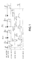
- Fig. 1 shows a pulse sequence employed in a conventional high-speed SE (Spin Echo) method.
- an excitation pulse R and a slice gradient ss are applied.
- a first inversion or reversal pulse P1 and a slice gradient ss are applied and a phase encode gradient gy(i) is applied to a warp axis.
- an NMR signal is received from a first echo SE1 while a read gradient rr is being applied to a read axis.
- a rewind gradient gyr(i) of opposite polarity which is equal in time integral value to the phase encode gradient gy(i), is applied to the warp axis.
- a second inversion pulse P2 and a slice gradient ss are applied and an encode gradient gy(i+1) is applied to the warp axis.
- an NMR signal is received form a second echo SE2 while a read gradient rr is being applied.
- a rewind gradient gyr(i+1) of opposite polarity which is identical in time integral value to the encode gradient gy(i+1) is applied to the warp axis.
- a third inversion pulse P3 and a slice gradient ss are applied and an encode gradient gy(i+2) is applied to the warp axis.
- an NMR signal is received from a third echo SE3 while a read gradient rr is being applied.
- a rewind gradient gyr(i+2) of opposite polarity which is equal in time integral value to the encode gradient gy(i+2), is applied to the warp axis.
- a killer gradient Kil is applied after a process from the transmission of the inversion pulse to the reception of the NMR signal has been repeated M times. This process is hereafter repeated N times in a repetitive time TR so that NMR signals subjected to different phase encodings corresponding to (M ⁇ N) times are collected on the warp axis.
- p 1, 2, ..., N.
- M 3 in Fig. 1.
- M ⁇ 4 is normally often used to shorten a scan time.
- i (p - 1)M + 1
- the terms (i), (i+1) and (i + 2) in the encode gradients gy(i), gy(i+1) and gy(i+2) indicate phase encode numbers, respectively.
- the killer gradient Kil shows a gradient pulse for spoiling transverse magnetization.
- the polarity of the killer gradient Kil is conventionally kept constant.
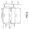
- Fig. 2 shows a locus of collection of data on k-space in the aforementioned pulse sequence Kp.
- the k-space Ksp is divided into three segments Sg1, Sg2 and Sg3.
- Data (e.g., tc1) about the first segment Sg1 is collected by a first echo SE1
- data (e.g., tc2) about the second segment Sg2 is collected by a second echo SE2.
- data (e.g., tc3) about the third segment Sg3 is collected by a third echo SE3.
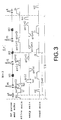
- Fig. 3 illustrates a pulse sequence employed in a conventional 3D (three-dimensional) high-speed SE method.
- an excitation pulse R and a slice gradient ss are applied.
- a rewind gradient gzr(0) of opposite polarity which is equal in time integral value to a phase encode gradient applied to a slice axis immediately before the application of the excitation pulse R and the slice gradient ss, is applied to the slice axis so as to be superimposed on a crusher gradient.
- a first inversion or reversal pulse P1 and a slice gradient are applied and a phase encode gradient gz(i) is applied to the slice axis so as to be superimposed on a crusher gradient.
- a phase encode gradient gy(i) is applied to a warp axis.
- an NMR signal is received from a first echo SE1 while a read gradient rr is being applied. Thereafter, a rewind gradient gyr(i) of opposite polarity, which is equal in time integral value to the encode gradient gy(i) applied to the warp axis, is applied to the warp axis and a rewind gradient gzr(i) of opposite polarity, which is equal in time integral value to the phase encode gradient gz(i) applied to the slice axis, is applied to the slice axis so as to be superimposed on a crusher gradient.
- a rewind gradient gyr(i) of opposite polarity which is equal in time integral value to the encode gradient gy(i) applied to the warp axis
- a rewind gradient gzr(i) of opposite polarity which is equal in time integral value to the phase encode gradient gz(i) applied to the slice axis
- a second inversion pulse P2 and a slice gradient are applied and a phase encode gradient gz(i+1) is applied to the slice axis so as to be superposed on a crusher gradient. Further, a phase encode gradient gy(i+1) is applied to the warp axis.
- an NMR signal is received from a second echo SE2 while a read gradient rr is being applied. Thereafter, a rewind gradient gyr(i+1) of opposite polarity, which is equal in time integral value to the phase encode gradient gy(i+1) applied to the warp axis, is applied to the warp axis.
- a rewind gradient gyr(i+1) of opposite polarity which is identical in time integral value to the phase encode gradient gz(i+1) applied to the slice axis, is applied to the warp axis so as to be superimposed on a crusher gradient.
- a third inversion or reversal pulse P3 and a slice gradient are applied and a phase encode gradient gz(i+2) is applied to the slice axis so as to be superimposed on a crusher gradient.
- a phase encode gradient gy(i+2) is applied to the warp axis.
- an NMR signal is received from a third echo SE3 while a read gradient rr is being applied.
- a rewind gradient gyr(i+2) of opposite polarity which is identical in time integral value to the phase encode gradient gy(i+2) applied to the warp axis, is applied to the warp axis.
- the amplitudes of the phase encode gradients gy(i), gy(i+1) and gy(i+2) applied to the warp axis are set as large as possible and each time width tgy is shortened in unison with the amplitude.
- the amplitudes of the phase encode gradients gz(i), gz(i+1) and gz(i+2) applied to the slice axis are set as large as possible and each time width tgz is shortened correspondingly.
- an MRI apparatus using a permanent magnet has a problem that the quality of an image is degraded due to residual magnetization developed in a magnetic shunt plate.
- the effect or influence of residual magnetization caused by a phase encode gradient becomes pronounced particularly when the sequence employed in the high-speed SE method is executed by the MRI apparatus using the permanent magnet.
- the residual magnetization having a strength ⁇ GY takes place due to a phase encode gradient gy(i) applied to a warp axis.
- the residual magnetization causes a first echo SE1 to produces a phase shift.
- Phase shifts occur in a second echo SE2, a third echo SE3, « in the same manner as described above.
- phase encode quantity cannot be returned to "0" due to a rewind gradient gyr(i). Hence this will exert an influence on the phases of the second and third echoes SE2 and SE3.
- the phase encode quantity cannot be returned to "0" in a manner similar to a rewind gradient gyr(i+1), a rewind gradient gyr(i+2), « either. Hence this will exert an influence on the phases of the subsequent echoes.
- phase of a stimulated echo STE (which is an abbreviation of STimulated Echo) produced simultaneously with a spin echo with that of the spin echo.
- these phases does not match with each other.
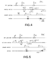
- the second echo SE2 most important to decide the contrast of an image and a second stimulated echo STE2 produced simultaneously with the second echo SE2 are illustrated in Fig. 4.
- the second echo SE2 is phase-shifted under the influence of the residual magnetization of the strength ⁇ GY(i) by the phase encode gradient gy(i).
- the phase of the second echo SE2 does not match with that of the second stimulated echo STE2.
- interference is produced between the two and hence a ghost Artifact, a shading Artifact and a Ringing Artifact appear on the image.
- the residual magnetization having a strength ⁇ GZ(i) is produced by a phase encode gradient gz(i) applied to a slice axis.
- the residual magnetization causes a first echo SE1 to produce a phase shift.
- Phase shifts occur in a second echo SE2, a third echo SE3, — in the same manner as described above.
- phase encode quantity cannot be returned to "0" due to a rewind gradient gzr(i). This will exert an influence on the phases of the second and third echoes SE2 and SE3.
- the phase encode quantity cannot be returned to "0" in a manner similar to a rewind gradient gzr(i+1), a rewind gradient gyr(i+2), « either. Hence, this will exert an influence on the phases of the subsequent echoes.
- phase of the second echo SE2 most important to decide the contrast of an image does not match with that of a second stimulated echo STE2 produced simultaneously with the second echo SE2, whereby an artifact occurs on the image.
- an object of the present invention to provide an MRI apparatus capable of preventing the quality of an image from being degraded under the influence of eddy currents and residual magnetization caused by a phase encode gradient.
- an MRI apparatus including an RF pulse transmitting means, a gradient magnetic field applying means and an NMR signal receiving means.
- an RF pulse is transmitted from the RF pulse transmitting means and a phase encode gradient is applied to a warp axis by the gradient magnetic field applying means.
- an NMR signal is received by the NMR signal receiving means.
- a rewind gradient obtained by adding a warp-axis correction component for correcting the influence of eddy currents or residual magnetization caused by the phase encode gradient to a basic component of opposite polarity equal in time integral value to the phase encode gradient is applied to the warp axis by the gradient magnetic field applying means.
- a rewind gradient equivalent to the basic component and an auxiliary rewind gradient equivalent to the warp-axis correction component are applied to the warp axis.
- they may be added together as either the amplitudes or time widths.
- they may be added together as both of the amplitudes and time widths.
- the rewind gradient composed of "(the basic component of opposite polarity equal in time integral time to the phase encode gradient) + (the warp-axis correction component for correcting the influence of the eddy currents or residual magnetization caused by the phase encode gradient)" is applied to the warp axis.
- the rewind gradient composed of (the basic component of opposite polarity equal in time integral value to the phase encode gradient) and the auxiliary rewind gradient composed of (the warp-axis correction component for correcting the influence of the eddy currents or residual magnetization caused by the phase encode gradient) are applied to the warp axis.
- the quantity of phase encoding is returned to "0" (original rewind) based on the basic component so that the influence of the eddy currents or residual magnetization caused by the phase encode gradient is canceled by the warp-axis correction component. It is therefore possible to prevent the quality of an image from being degraded under the influence of the eddy currents or residual magnetization caused by the phase encode gradient.
- an MRI apparatus including an RF pulse transmitting means, a gradient magnetic field applying means and an NMR signal receiving means.
- an RF pulse is transmitted from the RF pulse transmitting means.
- a phase encode gradient obtained by adding a warp-axis correction component for correcting the influence of eddy currents or residual magnetization caused by a phase encode gradient applied to a warp axis to a basic component of the phase encode gradient on the warp axis, which is determined by a scan parameter, is applied to the warp axis.
- a phase encode gradient equivalent to the basic component and an auxiliary phase encode gradient equivalent to the warp-axis correction component are applied to the warp axis.
- a rewind gradient of opposite polarity which is equal in time integral value to the basic component of the phase encode gradient, is applied to the warp axis.
- additional they may be added together as the amplitudes or time widths. Alternatively, they may be added together as both of the amplitudes and time widths.
- the phase encode gradient composed of "(the basic component of the phase encode gradient decided by the scan parameter) + (the warp-axis correction component for correcting the influence of the eddy currents or residual magnetization caused by the phase encode gradient)" is applied to the warp axis.
- the phase encode gradient composed of (the basic component of the phase encode gradient decided by the scan parameter) and the auxiliary phase encode gradient composed of (the warp-axis correction component for correcting the influence of the eddy currents or residual magnetization caused by the phase encode gradient) are applied to the warp axis.
- phase encode original phase encode
- the phase encode is effected based on the basic component so that the influence of the eddy currents or residual magnetization caused by the phase encode gradient is canceled by the warp-axis correction component. Therefore, the quality of an image can be prevented from being degraded under the influence of the eddy currents or residual magnetization caused by the phase encode gradient.
- the MRI apparatus having the above construction, which further includes a first phase information acquiring means for receiving an NMR signal through the NMR signal receiving means while the RF pulse transmitting means transmits an RF pulse and the gradient magnetic field applying means applies a read gradient to a read axis without applying the phase encode gradient to the warp axis and thereby obtaining first phase information from the received NMR signal, a second phase information acquiring means for receiving an NMR signal through the NMR signal receiving means while the RF pulse transmitting means transmits an RF pulse, the gradient magnetic field applying means applies an equivalent phase encode gradient equal in time integral value to the phase encode gradient to the read axis, applies an equivalent rewind gradient of opposite polarity equal in time integral value to the equivalent phase encode gradient to the read axis without applying the phase encode gradient to the warp axis, and then applies a read gradient to the read axis and thereby obtaining second phase information from the received NMR signal, and a warp-axis correction component calculating means
- the warp-axis correction component is determined as follows:
- the first phase information is equivalent to phase information, which is not placed under the influence of the eddy currents or residual magnetization caused by the phase encode gradient.
- the second phase information corresponds to phase information at the time that the influence of the eddy currents or residual magnetization caused by the phase encode gradient is equivalently exerted on the read axis.
- the MRI apparatus having the above construction, which further includes a present-existing phase information acquiring means for receiving an NMR signal through the NMR signal receiving means while the RF pulse transmitting means transmits an RF pulse and the gradient magnetic field applying means applies a phase encode gradient to a warp axis and then applies a read gradient to a read axis and thereby obtaining present-existing phase information from the received NMR signal, an ideal phase information acquiring means for receiving an NMR signal through the NMR signal receiving means while the RF pulse transmitting means transmits an RF pulse and the gradient magnetic field applying means applies a phase encode gradient whose time width and amplitude have been enlarged and reduced respectively, to the warp axis and then applies a read gradient to a read axis and thereby obtaining ideal phase information from the received NMR signal, and a warp-axis correction component calculating means for determining the warp-axis correction component from the present-existing phase information and the ideal phase information.
- the warp-axis correction component is determined as follows:
- the present-existing phase information corresponds to phase information including the influence of eddy currents or residual magnetization caused by the phase encode gradient.
- the ideal phase information is equivalent to phase information which does not include the influence of the eddy currents or residual magnetization caused by the phase encode gradient.
- an MRI apparatus wherein an NMR signal receiving means receives an NMR signal therein while an RF pulse transmitting means transmits an excitation RF pulse and an inversion RF pulse and a gradient magnetic field applying means applies a phase encode gradient to a warp axis and then applies a read gradient to a read axis, the gradient magnetic field applying means applies a killer gradient after a process from the transmission of the inversion RF pulse to the reception of the NMR signal has been repeated M times, and a process from the transmission of the excitation RF pulse to the application of the killer gradient is repeated N times thereby to collect NMR signals phase-encoded (M ⁇ N) times on a different basis.
- M ⁇ N phase-encoded
- the gradient magnetic field applying means switches the polarity of the killer gradient to the same polarity as that of the sum of phase encode gradients per M times, which are applied when the process from the transmission of the inversion RF pulse to the reception of the NMR signal is repeated M times.
- the polarity of the killer gradient is switched so as to become the same polarity as that of the sum of phase encode gradients per plural times, which are applied in the corresponding pulse train.
- the killer gradient since the polarity of the killer gradient is constant, the killer gradient merely functioned as a spoiler.
- the polarity of the killer gradient is switched to the same polarity as that of the sum of the phase encode gradients per plural times, which have been applied in the corresponding pulse train, the function of canceling the influence of eddy currents or residual magnetization caused by each phase encode gradient is also brought about. Therefore, the quality of an image can be prevented from being degraded under the influence of the eddy currents or residual magnetization caused by the phase encode gradient.
- an MRI apparatus wherein while an RF pulse transmitting means transmits an excitation RF pulse and an inversion RF pulse therefrom and a gradient magnetic field applying means next applies a phase encode gradient to a warp axis or applies it to the warp axis and a slice axis and thereafter applies a read gradient to a read axis, an NMR signal receiving means receives an NMR signal therein.
- a transmission phase of the inversion RF pulse transmitted from the RF pulse transmitting means is changed or a phase detected by the NMR signal receiving means is changed so as to suppress a 0-order phase component produced under the influence of residual magnetization caused by the phase encode gradient.
- the effect or influence of the residual magnetization caused by the phase encode gradient includes a 0-order phase component uniformly added without depending on the position and a first-order phase component linearly varied depending on the position.
- the 0-order phase component mainly produces a ghost Artifact whereas the first-order phase component mainly produces a Shading Artifact.
- the 0-order phase component is developed as an overall phase shift of the NMR signal, the 0-order phase component can be returned to the original state by changing the transmission phase of the inversion RF pulse transmitted from the RF pulse transmitting means or changing the phase detected by the NMR signal receiving means. Therefore, the ghost Artifact can be suppressed.
- the MRI apparatus having the aforementioned construction, which includes a 0-order phase component acquiring means for receiving an NMR signal through the NMR signal receiving means while the RF pulse transmitting means transmits an RF pulse, the gradient magnetic field applying means applies an equivalent phase encode gradient equal in time integral value to the phase encode gradient to the read axis and applies an equivalent rewind gradient of opposite polarity equal in time integral value to the equivalent phase encode gradient to the read axis without applying the phase encode gradient to the warp axis and the slice axis, and the gradient magnetic field applying means next applies a read gradient to the read axis, obtaining phase information from the received NMR signal and determining the 0-order phase component from the so-obtained phase information.
- the 0-order phase component is determined as follows:
- the phase information shows phase information at the time that the influence of eddy currents or residual magnetization caused by the phase encode gradient is exerted on the read axis.
- the MRI apparatus having the aforementioned construction, which further includes a 0-order phase component acquiring means for obtaining the 0-order phase component from an NMR signal obtained when the phase encode gradient and the rewind gradient are applied to the warp axis and an NMR signal obtained when the phase encode gradient and the rewind gradient are not applied to the warp axis.
- the 0-order phase component is determined as follows:
- the 0-order phase component associated with the influence of the eddy currents or residual magnetization caused by the phase encode gradient and the rewind gradient can be quantitatively recognized.
- phase encode gradient and the rewind gradient are applied to the warp axis, the influence of the eddy currents or residual magnetization caused by them is superimposed on the 0-order phase component.
- an MRI apparatus including an RF pulse transmitting means, a gradient magnetic field applying means and an NMR signal receiving means.
- an excitation pulse is applied by the RF pulse transmitting means.
- the RF pulse transmitting means transmits an inversion pulse therefrom
- the gradient magnetic field applying means applies a phase encode gradient to a slice axis
- the NMR signal receiving means receives an NMR signal therein.
- the gradient magnetic field applying means repeats the application of a rewind gradient obtained by adding a slice-axis correction component for correcting the influence of eddy currents or residual magnetization caused by the phase encode gradient to a basic component of opposite polarity equal in time integral value to the phase encode gradient, to the slice axis or the application of a rewind gradient equivalent to the basic component and an auxiliary rewind gradient equivalent to the slice-axis correction component to the slice axis by the number of encodings in a slice-axis direction.
- the rewind gradient comprised of "(the basic component of opposite polarity equal in time integral value to the phase encode gradient) + (the slice-axis correction component for correcting the influence of the eddy currents or residual magnetization caused by the phase encode gradient)" is applied to the slice axis.
- the rewind gradient comprised of (the basic component of opposite polarity equal in time integral value to the phase encode gradient) and the auxiliary rewind gradient comprised of (the slice-axis correction component for correcting the influence of the eddy currents and residual magnetization caused by the phase encode gradient) are applied to the slice axis.
- the quantity of phase encoding is returned to "0" (original rewind) based on the basic component so that the influence of the eddy currents or residual magnetization caused by the phase encode gradient is canceled by the slice-axis correction component. Therefore, the quality of an image can be prevented from being degraded under the influence of the eddy currents or residual magnetization.
- the MRI apparatus having the above-described construction, which further includes a first phase information acquiring means for receiving an NMR signal through the NMR signal receiving means while the RF pulse transmitting means transmits an RF pulse and the gradient magnetic field applying means applies a read gradient to a read axis without applying the phase encode gradient to the slice axis and thereby obtaining first phase information from the received NMR signal, a second phase information acquiring means for receiving an NMR signal through the NMR signal receiving means while the RF pulse transmitting means transmits an RF pulse, the gradient magnetic field applying means applies a difference gradient equivalent to a difference between the phase encode gradient and a basic component of a subsequent rewind gradient to the read axis, applies an equivalent phase encode gradient equal in time integral value to the phase encode gradient and an equivalent rewind gradient equal in time integral value to the basic component of the rewind gradient to the read axis without applying the phase encode gradient to the slice axis and then applies a read gradient to the read axi
- the slice-axis correction component is determined as follows:
- the first phase information corresponds to phase information which is not affected by the eddy currents or residual magnetization caused by the phase encode gradient.
- the second phase information is of phase information at the time that the influence of the eddy currents or residual magnetization caused by the phase encode gradient is equivalently exerted onto the read axis.
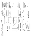
- Fig. 6 is a block diagram showing an MRI apparatus according to a first embodiment of the present invention.
- a magnet assembly 1 has a space portion (hole) for inserting an object to be examined or a sample thereinside.
- a permanent magnet 1p for applying a predetermined main magnetic field to the sample, a gradient magnetic field coil 1g for generating or producing gradient magnetic fields for a slice axis, a warp axis and a read axis, a transmitting coil 1t for supplying an RF pulse used for exciting a spin of an atomic nucleus in the sample, and a receiving coil 1r for detecting an NMR signal from the sample are provided in the MRI apparatus 100 so as to surround the space portion.
- the gradient magnetic filed coil 1g, the transmitting coil 1t and the receiving coil 1r are respectively electrically connected to a gradient magnetic field drive circuit 3, an RF power amplifier 4 and a preamplifier 5.
- a sequence storage circuit 8 operates the gradient magnetic field drive circuit 3 based on a pulse sequence stored therein to produce a gradient magnetic field from the gradient magnetic field coil 1g of the magnet assembly 1. Further, the sequence storage circuit 8 operates a gate modulation circuit 9 to convert a carrier output signal produced from an RF oscillating circuit 10 into a pulse-shaped signal of a predetermined timing and a predetermined envelope shape and sends the modulated signal to the RF power amplifier 4 as an RF pulse, where it is subjected to power amplification. Thereafter, the so-amplified signal is applied to the transmitting coil 1t of the magnet assembly 1 to selectively excite an intended slice region.
- the preamplifier 5 amplifies the NMR signal detected from the sample by the receiving coil 1r of the magnet assembly 1 and inputs the amplified signal to a phase detector 12.
- the phase detector 12 determines the carrier output signal produced from the RF oscillating circuit 10 as a reference signal. Further, the phase detector 12 phase-detects the NMR signal sent from the preamplifier 5 and supplies it to an A/D converter 11.
- the A/D converter 11 converts the phase-detected analog signal into a digital signal and inputs it to the computer 7.
- the computer 7 reads data from the A/D converter 11 and performs an image reconfigurating computation on it to produce an image in the intended slice region.
- the image is displayed on a display unit 6. Further, the computer 7 takes or performs the overall control such as reception of information inputted from a console 13, or the like.
- Fig. 7 is a flowchart for describing a warp-axis correction component acquiring process employed in the MRI apparatus 100.
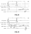
- Step S1 data sy0(k) is collected in accordance with a pulse sequence A0 shown in Fig. 8.
- a pulse sequence A0 an excitation pulse R and a slice gradient ss are first applied and an inversion pulse P and a slice gradient ss are next applied.
- an NMR signal is received from an echo SE while a read gradient gxw is being applied thereby to collect the data sy0(k).
- a phase encode gradient is not applied to a warp axis.
- the data sy0(k) is one-dimensionally Fourier-transformed in a read direction and the result of Fourier transformation is defined as SY0(x).
- the phase quantity b0 corresponds to a phase quantity at the center of the gradient at the time that no residual magnetization exists.
- Steps S1 through S3 referred to above are equivalent to a process for determining an influence or effect (a shift or displacement from the echo center of the echo signal SE) of eddy currents mainly caused by the gradient magnetic fields gx1 and gxw.
- Step S4 data syi(k) is collected in accordance with a pulse sequence Aj shown in Fig. 9.
- an excitation pulse R and a slice gradient ss are first applied and an equivalent phase encode gradient gy(i) equal in time integral value to a phase encode gradient gy(i) of an encode number i determined by a scan parameter is next applied to a read axis.
- an equivalent rewind gradient gyr(i) of opposite polarity which is equal in time integral value to the equivalent phase encode gradient gy(i) is applied to the read axis.
- Step S5 the data syi(k) is one-dimensionally Fourier-transformed in a read direction and the result of Fourier transformation is defined as SYi(x).
- the difference (bi-b0) corresponds to a 0-order phase component which is uniformly added without depending on the position under the influence of residual magnetization caused by the phase encode gradient gy(i).
- Steps S4 through S6 referred to above correspond to a process for determining an influence or effect of the residual magnetization mainly caused by the phase encode gradient gy(i).
- a magnitude ⁇ GY(i) of an influence or effect of the eddy currents and residual magnetization caused by the equivalent phase encode gradient gy(i) is calculated from (dyi - dy0).
- dy0 indicates a phase cycle or rotation at the time that no phase encode gradient exists.
- dyi indicates a phase cycle or rotation at the time that the equivalent phase encode gradient gy(i) exists. Since the equivalent phase encode gradient gy(i) is originally canceled by the equivalent rewind gradient gyr(i), (dyi - dy0) should have been equal to 0. Thus, if (dyi - dy0) ⁇ 0 , the magnitude of the difference therebetween represents the magnitude of the influence of the eddy currents and residual magnetization caused by the equivalent phase encode gradient gy(i). Accordingly, ⁇ GY(i) corresponding to the magnitude of the influence of the eddy currents and residual magnetization caused by the equivalent phase encode gradient gy(i) can be calculated from (dyi - dy0).
- Fig. 10 is a flowchart for describing an imaging data collecting process employed in the MRI apparatus 100.
- Step S11 imaging data are collected in accordance with a pulse sequence Bp employed in a high-speed SE method using the new rewind gradient gyr(i)' shown in Fig. 11.
- the phase detected by the phase detector 12 is adjusted or the corresponding transmission phases of inversion pulses P1, P2 and P3 are adjusted so as to cancel a difference (bi - b0) in phase quantity.
- imaging is performed using the imaging data collected in the above-described manner, it is possible to prevent the quality of an image from being degraded under the influence of the eddy currents and residual magnetization caused by the phase encode gradient on the warp axis.
- the second embodiment shows a modification of the first embodiment.
- a warp-axis correction component qi is acquired in a manner similar to the first embodiment.
- imaging data are collected in accordance with a pulse sequence Cp shown in Fig. 12 in place of the pulse sequence Bp shown in Fig. 11.
- a rewind gradient gyr(i) equivalent to the aforementioned basic component gy(i) is applied to a warp axis and an auxiliary rewind gradient gqr(i) equivalent to the aforementioned warp-axis correction component qi is applied to the warp axis.
- the third embodiment shows a modification of the first embodiment.
- a warp-axis correction component qi is obtained in the same manner as described in the first embodiment.
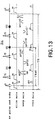
- a new phase encode gradient gy(i)' is determined from a basic component gy(i) of a phase encode gradient determined by a scan parameter and the warp-axis correction component qi.
- imaging data are collected in accordance with a pulse sequence Dp employed in a high-speed SE method using the new phase encode gradient gy(i)' as shown in Fig. 13.
- the fourth embodiment shows a modification of the first embodiment.
- a warp-axis correction component qi is acquired in a manner similar to the first embodiment.
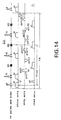
- a phase encode gradient gy(i) equivalent to the aforementioned basic component gy(i) is applied to a warp axis and imaging data are collected in accordance with a pulse sequence Ep employed in a high-speed SE method wherein an auxiliary phase encode gradient gq(i) equivalent to the aforementioned warp-axis correction component qi is applied to the warp axis.
- a warp-axis correction component acquiring process shown in Fig. 15 is executed in place of the warp-axis correction component acquiring process shown in Fig. 7.
- Fig. 15 is a flowchart for describing the warp-axis correction component acquiring process employed in the fifth embodiment.
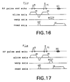
- Step V1 data sBi(k) is collected from a first echo in accordance with a pulse sequence F1p shown in Fig. 16 using an ith phase encode gradient gy(i)B having an amplitude equivalent to such a degree that it is possible to neglect the influence of eddy currents and residual magnetization owing to a phase encode quantity equal to an ith phase encode gradient gy(i) decided by a scan parameter.
- the data sBi(k) is one-dimensionally Fourier-transformed in a read direction and the result of Fourier transformation is defined as SBi(x).
- the ideal phase information ⁇ i represents an offset component (0-order phase component) of a phase at the time of the absence of the influence of the eddy currents and residual magnetization caused by the phase encode gradient.
- Step V4 data sBi'(k) is collected from a first echo in accordance with a pulse sequence Flp' shown in Fig. 17 using an ith phase encode gradient gy(i) determined by a scan parameter.
- the data sBi'(k) is one-dimensionally Fourier-transformed in a read direction and the result of Fourier transformation is defined as SBi'(x).
- the phase information ⁇ i' shows an offset component (0-order phase component) of a phase at the time of the presence of the influence of the eddy currents and residual magnetization caused by the phase encode gradient.
- a warp-axis correction component qi to be added for matching the phase information ⁇ i' with the ideal phase information ⁇ i is calculated based on magnet characteristics of the permanent magnet type MRI apparatus.
- Step V8 q(i+M-1) is determined from a warp-axis correction component q(i+1) based on echoes from a second echo to an Mth echo in a manner similar to Steps V1 through V7 referred to above.
- Figs. 18 and 19 respectively show pulse sequences F2p and F2p' at the time of the second echo.
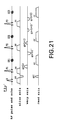
- Figs. 20 and 21 respectively illustrate pulse sequences F3p and F3p' at the time of the third echo.
- the imaging data shown in Figs. 10 through 14 are collected using the thus-determined warp-axis correction component qi. Even if imaging is performed using the imaging data, the quality of an image can be prevented from being degraded under the influence of the eddy currents and residual magnetization caused by the phase encode gradient.
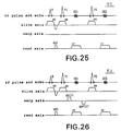
- the sixth embodiment shows the case where the influence of eddy currents or residual magnetization caused by a phase encode gradient is suppressed by switching the polarity of a killer slant or gradient.
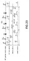
- Figs. 22 and 23 respectively show pulse sequences employed in the sixth embodiment.
- an excitation pulse R and a slice gradient ss are applied.
- a first inversion pulse P1 and a slice gradient ss are applied and a phase encode gradient gy(i) is applied to a warp axis.
- An NMR signal is next received from a first echo SE1 while a read gradient rr is being applied, followed by application of a rewind gradient gyr(i) of opposite polarity equal in time integral value to the encode gradient gy(i) to a warp axis.
- a second inversion pulse P2 and a slice gradient ss are applied and an encode gradient gy(i+1) is applied to the warp axis.
- the NMR signal is received from a second echo SE2 while another read gradient rr is being applied, followed by application of a rewind gradient gyr(i+1) of opposite polarity equal in time integral value to the encode gradient gy(i+1) to the warp axis.
- a third inversion pulse P3 and a slice gradient ss are applied and an encode gradient gy(i+2) is applied to the warp axis.
- the NMR signal is received from a third echo SE3 while a further read gradient rr is being applied, followed by application of a rewind gradient gyr(i+2) of opposite polarity equal in time integral value to the encode gradient gy(i+2) to the warp axis.
- a killer gradient Kil is applied.
- the polarity (positive in the present sequence) of the killer gradient Kil is made equal to that of the sum of the aforementioned phase encode gradients gy(i), gy(i+1) and gy(i+2).
- a process from the transmission of an excitation pulse R to the application of a rewind gradient gyr(j+2) is performed in the same manner as shown in Fig. 22.
- a killer gradient Kil is next applied.
- the polarity (negative in the present sequence) of the killer gradient Kil is made equal to that of the sum of phase encode gradients gy(j), gy(j+1) and gy(j+2).
- the polarity of the killer gradient Kil is switched to the same polarity as that of the sum of the phase encode gradients corresponding to the M times, which are applied when the process from the transmission of the inversion or reversal RF pulse to the reception of the NMR signal is repeated M times, the influence of the eddy currents or residual magnetization caused by the phase encode gradient can be canceled by the killer gradient Kil. It is therefore possible to prevent the quality of an image from being degraded under the influence of the eddy current or residual magnetization caused by the phase encode gradient.
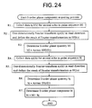
- Fig. 24 is a flowchart for describing a 0-order phase component acquiring process employed in the MRI apparatus 100.
- Step R1 data sy0(k) associated with a second echo SE2 is collected in accordance with a pulse sequence H0 in which no phase encode gradient and rewind gradient are applied to a warp axis.
- the data sy0(k) is one-dimensionally Fourier-transformed in a read direction and the result of Fourier transformation is defined as SY0(x).
- a 0-order phase quantity b0 Arctan(SY0(0)) is determined.
- the 0-order phase quantity b0 shows a phase quantity at the gradient center at the time that no residual magnetization exists.
- Step R4 data syj(k) associated with a second echo SE2 is collected in accordance with a pulse sequence Hj in which a phase encode gradient gy(i) and a rewind gradient gyr(i)' are applied to a warp axis.
- the rewind gradient gyr(i)' corresponds to a new rewind gradient gyr(i)' determined from a basic component gy(i) of the phase encode gradient determined by a scan parameter and a warp-axis correction component qi.
- the data syj(k) is one-dimensionally Fourier-transformed in a read direction and the result of Fourier transformation is defined as SYj(x).
- a 0-order phase quantity bj Arctan ⁇ SYj(0) ⁇ is determined.
- the 0-order phase quantity bj shows a phase quantity at the gradient center at the time that the residual magnetization exists.
- a 0-order phase component bi b0 - bj is determined.
- the eighth embodiment is intended to prevent degradation of the quality of an image, which occurs due to the influence of eddy currents or residual magnetization caused by a phase encode gradient of a slice axis employed in a 3D high-speed SE method.
- Fig. 27 is a flowchart for describing a slice axis correction component acquiring process employed in the MRI apparatus 100.
- Step L1 data sz0(k) is collected in accordance with a pulse sequence I0 shown in Fig. 28.
- a pulse sequence I0 an excitation pulse R and a slice gradient ss are applied.
- an inversion or reversal pulse P and a slice gradient ss are applied.
- an NMR signal is received from an echo SE while a read gradient gxw is being applied, thereby collecting the data sz0(k).
- no phase encode gradient is applied to a warp axis and a slice axis.
- the data sz0(k) is one-dimensionally Fourier-transformed in a read direction and the result of Fourier transformation is defined as SZ0(x).
- Steps L1 through L3 referred to above show a process for acquiring an influence or effect (a shift or displacement of an echo center of an echo signal SE) of eddy currents mainly caused by gradient magnetic fields gx1 and gxw.
- Step L4 data szi(k) is collected in accordance with a pulse sequence Ij shown in Fig. 29.
- a pulse sequence Ij an excitation pulse R is applied and a slice gradient ss is applied to a slice axis.
- a difference gradient dd corresponding to the difference between a phase encode gradient gz(i) and a rewind gradient gzr(i) on the slice axis, each being indicated by an encode number i determined by a scan parameter, is applied to a read axis.
- an equivalent phase encode gradient gz(i) equal to the phase encode gradient gz(i) applied to the slice axis is applied to the read axis and an inversion or reversal pulse P and a slice gradient ss are applied. Thereafter, an equivalent rewind gradient gzr(i) equal to the rewind gradient gzr(i) on the slice axis is applied to the read axis. After a time t has elapsed, an NMR signal is received from an echo SE while a read gradient gxw is being applied, thereby to collect the data szi(k). Incidentally, no phase encode gradient is applied to a warp axis.
- the data szi(k) is one-dimensionally Fourier-transformed in a read direction and the result of Fourier transformation is defined as SZi(x).
- the difference (bi - b0) corresponds to a 0-order phase component which is uniformly added without depending on the position under the influence of residual magnetization caused by the phase encode gradient gz(i).
- Steps L4 through L6 referred to above correspond to a process for determining an influence or effect of the residual magnetization mainly caused by the phase encode gradient gz(i).
- a magnitude ⁇ GZ(i) of an influence or effect of the eddy currents and residual magnetization caused by the phase encode gradient gz(i) is calculated from (dzi - dz0).
- dz0 indicates a phase cycle or rotation at the time that no phase encode gradient exists.
- dzi indicates a phase cycle or rotation at the time that the phase encode gradient gz(i) exists. Since the phase encode gradient gz(i) is originally canceled by the rewind gradient gzr(i), (dzi - dz0) should have been equal to 0. Thus, if (dzi - dz0) ⁇ 0 , then the magnitude of the difference therebetween represents the magnitude of the influence of the eddy currents and residual magnetization caused by the phase encode gradient gz(i). Accordingly, ⁇ GZ(i) corresponding to the magnitude of the influence of the eddy currents and residual magnetization caused by the phase encode gradient gz(i) can be calculated from (dzi - dz0).
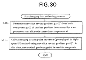
- Fig. 30 is a flowchart for describing an imaging data collecting process.
- imaging data are collected in accordance with a pulse sequence Jp employed in a 3D high-speed SE method using the new rewind gradient gzr(i)' shown in Fig. 31 on the slice axis.
- the aforementioned new rewind gradient gyr(i)' on the warp axis which is employed in the first embodiment, may preferably be used simultaneously.
- the phase detected by the phase detector 12 is adjusted or the corresponding transmission phases of inversion or reversal pulses P1, P2 and P3 are adjusted so as to cancel the difference in phase quantity (bi - b0).
- an auxiliary rewind gradient and an auxiliary phase encode gradient on a slice axis may be used in the same manner as described with reference to Figs. 7 through 9.
- imaging is performed using the imaging data collected in the above-described manner, it is then possible to prevent the quality of an image from being degraded under the influence of the eddy currents and residual magnetization caused by the phase encode gradient on the slice axis.
- the quality of the image can be prevented from being degraded under the influence of the eddy currents or residual magnetization caused by the phase encode gradient.
- the MRI apparatus using the permanent magnet is particularly useful in improvements in the quality of an image.
Landscapes
- Physics & Mathematics (AREA)
- Health & Medical Sciences (AREA)
- General Health & Medical Sciences (AREA)
- Nuclear Medicine, Radiotherapy & Molecular Imaging (AREA)
- Radiology & Medical Imaging (AREA)
- Engineering & Computer Science (AREA)
- Signal Processing (AREA)
- High Energy & Nuclear Physics (AREA)
- Condensed Matter Physics & Semiconductors (AREA)
- General Physics & Mathematics (AREA)
- Magnetic Resonance Imaging Apparatus (AREA)
Priority Applications (4)
| Application Number | Priority Date | Filing Date | Title |
|---|---|---|---|
| EP01104749A EP1115006B1 (de) | 1995-03-28 | 1996-03-20 | MRI-Gerät |
| EP01104751A EP1103819B1 (de) | 1995-03-28 | 1996-03-20 | MRI-Gerät |
| EP01104752A EP1103820A1 (de) | 1995-03-28 | 1996-03-20 | MRI-Gerät |
| EP01104753A EP1115007B1 (de) | 1995-03-28 | 1996-03-20 | MRI-Gerät |
Applications Claiming Priority (6)
| Application Number | Priority Date | Filing Date | Title |
|---|---|---|---|
| JP6908295 | 1995-03-28 | ||
| JP6908295 | 1995-03-28 | ||
| JP69082/95 | 1995-03-28 | ||
| JP24285795A JP3505294B2 (ja) | 1995-03-28 | 1995-09-21 | Mri装置 |
| JP242857/95 | 1995-09-21 | ||
| JP24285795 | 1995-09-21 |
Related Child Applications (7)
| Application Number | Title | Priority Date | Filing Date |
|---|---|---|---|
| EP01104753A Division EP1115007B1 (de) | 1995-03-28 | 1996-03-20 | MRI-Gerät |
| EP01104751A Division EP1103819B1 (de) | 1995-03-28 | 1996-03-20 | MRI-Gerät |
| EP01104749A Division EP1115006B1 (de) | 1995-03-28 | 1996-03-20 | MRI-Gerät |
| EP01104751.1 Division-Into | 2001-02-26 | ||
| EP01104753.7 Division-Into | 2001-02-26 | ||
| EP01104749.5 Division-Into | 2001-02-26 | ||
| EP01104752.9 Division-Into | 2001-02-26 |
Publications (3)
| Publication Number | Publication Date |
|---|---|
| EP0735379A2 true EP0735379A2 (de) | 1996-10-02 |
| EP0735379A3 EP0735379A3 (de) | 1997-02-26 |
| EP0735379B1 EP0735379B1 (de) | 2003-11-12 |
Family
ID=26410260
Family Applications (5)
| Application Number | Title | Priority Date | Filing Date |
|---|---|---|---|
| EP96104442A Expired - Lifetime EP0735379B1 (de) | 1995-03-28 | 1996-03-20 | Gerät zur Bilderzeugung mit magnetischer Resonanz |
| EP01104751A Expired - Lifetime EP1103819B1 (de) | 1995-03-28 | 1996-03-20 | MRI-Gerät |
| EP01104749A Expired - Lifetime EP1115006B1 (de) | 1995-03-28 | 1996-03-20 | MRI-Gerät |
| EP01104752A Withdrawn EP1103820A1 (de) | 1995-03-28 | 1996-03-20 | MRI-Gerät |
| EP01104753A Expired - Lifetime EP1115007B1 (de) | 1995-03-28 | 1996-03-20 | MRI-Gerät |
Family Applications After (4)
| Application Number | Title | Priority Date | Filing Date |
|---|---|---|---|
| EP01104751A Expired - Lifetime EP1103819B1 (de) | 1995-03-28 | 1996-03-20 | MRI-Gerät |
| EP01104749A Expired - Lifetime EP1115006B1 (de) | 1995-03-28 | 1996-03-20 | MRI-Gerät |
| EP01104752A Withdrawn EP1103820A1 (de) | 1995-03-28 | 1996-03-20 | MRI-Gerät |
| EP01104753A Expired - Lifetime EP1115007B1 (de) | 1995-03-28 | 1996-03-20 | MRI-Gerät |
Country Status (6)
| Country | Link |
|---|---|
| US (1) | US5729139A (de) |
| EP (5) | EP0735379B1 (de) |
| JP (1) | JP3505294B2 (de) |
| KR (1) | KR100225321B1 (de) |
| CN (3) | CN100419450C (de) |
| DE (4) | DE69637598D1 (de) |
Cited By (6)
| Publication number | Priority date | Publication date | Assignee | Title |
|---|---|---|---|---|
| EP0818689A1 (de) * | 1996-07-11 | 1998-01-14 | Ge Yokogawa Medical Systems, Ltd. | Verfahren in der Bilderzeugung durch magnetische Resonanz zur Messung der Phasenverschiebung, zur Korrektur der Phasenverschiebung und Gerät für die Bilderzeugung durch magnetisch Resonanz, das diese Verfahren ausführt |
| EP1004893A1 (de) * | 1998-11-23 | 2000-05-31 | General Electric Company | Ein Verfahren zur Kompensierung eines MRI-Systems für verbleibende Magnetisierung |
| EP1004892A1 (de) * | 1998-11-23 | 2000-05-31 | General Electric Company | Kompensierung eines MRI-Systems für verbleibende Magnetisierung |
| DE19801808B4 (de) * | 1997-02-11 | 2009-06-04 | General Electric Co. | Vorrichtung und Verfahren zur Verringerung von Maxwell-Term-Artefakten bei schnellen Spinecho-Magnetresonanzbildern |
| EP2824473A1 (de) * | 2013-07-08 | 2015-01-14 | Samsung Electronics Co., Ltd | Kompensation von Wirbelstromfeldern und Gradientenoffsets in der bildgebenden magnetischen Resonanz |
| JP2015128552A (ja) * | 2014-01-09 | 2015-07-16 | 株式会社日立メディコ | 磁気共鳴イメージング装置、及びその磁場印加方法 |
Families Citing this family (25)
| Publication number | Priority date | Publication date | Assignee | Title |
|---|---|---|---|---|
| JP3453089B2 (ja) * | 1999-08-20 | 2003-10-06 | ジーイー横河メディカルシステム株式会社 | Mri装置 |
| US6392411B1 (en) * | 2000-01-03 | 2002-05-21 | Ge Yokogawa Medical Systems, Limited | MR imaging method, phase shift measuring method and MR imaging system |
| JP3853585B2 (ja) * | 2000-10-11 | 2006-12-06 | ジーイー・メディカル・システムズ・グローバル・テクノロジー・カンパニー・エルエルシー | Mri装置 |
| JP3858191B2 (ja) | 2000-10-31 | 2006-12-13 | ジーイー・メディカル・システムズ・グローバル・テクノロジー・カンパニー・エルエルシー | Mri装置 |
| DE10063676B4 (de) | 2000-12-20 | 2006-08-17 | Siemens Ag | Multiecho-Bildgebungsverfahren |
| JP3878429B2 (ja) * | 2001-04-05 | 2007-02-07 | ジーイー・メディカル・システムズ・グローバル・テクノロジー・カンパニー・エルエルシー | Mri装置 |
| JP3814157B2 (ja) * | 2001-04-17 | 2006-08-23 | ジーイー・メディカル・システムズ・グローバル・テクノロジー・カンパニー・エルエルシー | Mri装置 |
| JP3884243B2 (ja) * | 2001-06-21 | 2007-02-21 | ジーイー・メディカル・システムズ・グローバル・テクノロジー・カンパニー・エルエルシー | 外部磁界測定方法、静磁界補正方法、外部磁界測定装置およびmri装置 |
| US6628116B1 (en) * | 2001-09-06 | 2003-09-30 | Ge Medical Systems Global Technology Co., Llc | Process and apparatus to remove stimulated echo artifacts caused by interactions of a preparation sequence with a gradient echo sequence in MR imaging |
| JP3720752B2 (ja) * | 2001-10-26 | 2005-11-30 | ジーイー・メディカル・システムズ・グローバル・テクノロジー・カンパニー・エルエルシー | 0次位相検出方法およびmri装置 |
| JP3796455B2 (ja) * | 2002-02-22 | 2006-07-12 | ジーイー・メディカル・システムズ・グローバル・テクノロジー・カンパニー・エルエルシー | Mri装置 |
| EP1504274B1 (de) * | 2002-05-15 | 2008-03-05 | Siemens Aktiengesellschaft | Magnetresonanzanlage |
| JP4347788B2 (ja) | 2004-12-01 | 2009-10-21 | ジーイー・メディカル・システムズ・グローバル・テクノロジー・カンパニー・エルエルシー | Mri装置 |
| CN100339050C (zh) * | 2005-09-20 | 2007-09-26 | 华东师范大学 | 一种磁共振成像系统中减小梯度线圈涡流的方法 |
| JP4576534B2 (ja) * | 2006-03-28 | 2010-11-10 | 国立大学法人 筑波大学 | 磁気共鳴イメージング装置および撮像方法 |
| JP5022696B2 (ja) * | 2006-12-22 | 2012-09-12 | ジーイー・メディカル・システムズ・グローバル・テクノロジー・カンパニー・エルエルシー | 磁気共鳴イメージング装置 |
| CN101636663B (zh) * | 2007-03-19 | 2013-11-20 | 皇家飞利浦电子股份有限公司 | 磁共振设备和方法 |
| US9423480B2 (en) * | 2008-10-27 | 2016-08-23 | The University Of Western Ontario | System and method for magnetic resonance imaging |
| JP5611882B2 (ja) * | 2010-05-31 | 2014-10-22 | 株式会社東芝 | 磁気共鳴イメージング装置 |
| JP5925529B2 (ja) * | 2011-03-31 | 2016-05-25 | 株式会社東芝 | 磁気共鳴イメージング装置 |
| JP6591208B2 (ja) * | 2015-06-09 | 2019-10-16 | キヤノンメディカルシステムズ株式会社 | 磁気共鳴イメージング装置 |
| CN107621616B (zh) * | 2017-08-01 | 2019-12-13 | 国家纳米科学中心 | 一种磁共振投影成像方法及装置 |
| EP3680680A1 (de) * | 2019-01-11 | 2020-07-15 | Siemens Healthcare GmbH | Verfahren zum erhalt eines optimierten betriebsparameters, speichermedium und magnetresonanzgerät |
| CN109946632B (zh) * | 2019-03-06 | 2023-10-20 | 佛山瑞加图医疗科技有限公司 | 剩磁相位差测量方法及剩磁测量方法 |
| CN110261801A (zh) * | 2019-06-19 | 2019-09-20 | 上海东软医疗科技有限公司 | 一种射频激励方法及装置 |
Family Cites Families (17)
| Publication number | Priority date | Publication date | Assignee | Title |
|---|---|---|---|---|
| US4484138A (en) * | 1982-07-01 | 1984-11-20 | General Electric Company | Method of eliminating effects of spurious free induction decay NMR signal caused by imperfect 180 degrees RF pulses |
| US4665365A (en) * | 1985-01-07 | 1987-05-12 | General Electric Company | Method for reversing residual transverse magnetization due to phase-encoding magnetic field gradients |
| US4647858A (en) * | 1985-07-29 | 1987-03-03 | General Electric Company | Methods for overcoming transient magnetic field inhomogeneity in nuclear magnetic resonance imaging |
| JPS6245917A (ja) * | 1985-08-23 | 1987-02-27 | Honda Motor Co Ltd | 内燃機関の動弁装置 |
| DE3637998A1 (de) * | 1986-11-07 | 1988-05-11 | Max Planck Gesellschaft | Verfahren zur schnellen akquisition von spinresonanzdaten fuer eine ortsaufgeloeste untersuchung eines objekts |
| US5055790A (en) * | 1989-07-13 | 1991-10-08 | Picker International, Inc. | Ssfp imaging technique with improved t1 contrast |
| NL9002842A (nl) * | 1990-12-21 | 1992-07-16 | Philips Nv | Magnetische resonantie werkwijze en inrichting ter reductie van beeldfouten in een magnetisch resonantie beeld. |
| US5227728A (en) * | 1991-11-01 | 1993-07-13 | The Regents Of The University Of California | Gradient driver control in magnetic resonance imaging |
| JPH05285116A (ja) * | 1992-04-14 | 1993-11-02 | Toshiba Corp | 磁気共鳴イメージング方法 |
| DE69326202T2 (de) * | 1992-06-29 | 2000-04-13 | Koninklijke Philips Electronics N.V., Eindhoven | Verfahren und Gerät zur Kernresonanzabbildung |
| DE69329873T2 (de) * | 1992-10-26 | 2001-09-13 | Koninklijke Philips Electronics N.V., Eindhoven | Kompensierung von Wirbelströmen in der Bilderzeugung mittels magnetischer Resonanz |
| EP0595391B1 (de) * | 1992-10-26 | 2001-01-17 | Koninklijke Philips Electronics N.V. | Kompensierung von Wirbelströmen in der Bilderzeugung mittels magnetischer Resonanz |
| JPH06245917A (ja) * | 1993-02-23 | 1994-09-06 | Yokogawa Medical Syst Ltd | Mri装置 |
| JP2737608B2 (ja) * | 1993-07-31 | 1998-04-08 | 株式会社島津製作所 | Mrイメージング装置 |
| WO1995004939A2 (en) * | 1993-08-02 | 1995-02-16 | The Board Of Trustees Of The Leland Stanford Junior University | Apparatus and method for decreasing magnetic field sensitivity of long rf pulses |
| JP2755125B2 (ja) * | 1993-09-30 | 1998-05-20 | 株式会社島津製作所 | Mrイメージング装置 |
| JP3483947B2 (ja) * | 1993-10-14 | 2004-01-06 | 株式会社東芝 | 磁気共鳴イメージング装置 |
-
1995
- 1995-09-21 JP JP24285795A patent/JP3505294B2/ja not_active Expired - Fee Related
-
1996
- 1996-02-20 US US08/603,672 patent/US5729139A/en not_active Expired - Lifetime
- 1996-03-20 DE DE69637598T patent/DE69637598D1/de not_active Expired - Fee Related
- 1996-03-20 EP EP96104442A patent/EP0735379B1/de not_active Expired - Lifetime
- 1996-03-20 EP EP01104751A patent/EP1103819B1/de not_active Expired - Lifetime
- 1996-03-20 DE DE69630625T patent/DE69630625T2/de not_active Expired - Fee Related
- 1996-03-20 DE DE69637202T patent/DE69637202T2/de not_active Expired - Fee Related
- 1996-03-20 EP EP01104749A patent/EP1115006B1/de not_active Expired - Lifetime
- 1996-03-20 DE DE69636397T patent/DE69636397T2/de not_active Expired - Fee Related
- 1996-03-20 EP EP01104752A patent/EP1103820A1/de not_active Withdrawn
- 1996-03-20 EP EP01104753A patent/EP1115007B1/de not_active Expired - Lifetime
- 1996-03-27 KR KR1019960009890A patent/KR100225321B1/ko not_active Expired - Fee Related
- 1996-03-28 CN CNB2003101028400A patent/CN100419450C/zh not_active Expired - Fee Related
- 1996-03-28 CN CNB961041404A patent/CN100465659C/zh not_active Expired - Fee Related
-
2001
- 2001-03-28 CN CNB011124202A patent/CN1204412C/zh not_active Expired - Fee Related
Cited By (9)
| Publication number | Priority date | Publication date | Assignee | Title |
|---|---|---|---|---|
| EP0818689A1 (de) * | 1996-07-11 | 1998-01-14 | Ge Yokogawa Medical Systems, Ltd. | Verfahren in der Bilderzeugung durch magnetische Resonanz zur Messung der Phasenverschiebung, zur Korrektur der Phasenverschiebung und Gerät für die Bilderzeugung durch magnetisch Resonanz, das diese Verfahren ausführt |
| US6127825A (en) * | 1996-07-11 | 2000-10-03 | Ge Yokogawa Medical Systems, Limited | Method of phase shift measurement, method of phase correction, and MRI apparatus |
| DE19801808B4 (de) * | 1997-02-11 | 2009-06-04 | General Electric Co. | Vorrichtung und Verfahren zur Verringerung von Maxwell-Term-Artefakten bei schnellen Spinecho-Magnetresonanzbildern |
| EP1004893A1 (de) * | 1998-11-23 | 2000-05-31 | General Electric Company | Ein Verfahren zur Kompensierung eines MRI-Systems für verbleibende Magnetisierung |
| EP1004892A1 (de) * | 1998-11-23 | 2000-05-31 | General Electric Company | Kompensierung eines MRI-Systems für verbleibende Magnetisierung |
| KR100671090B1 (ko) * | 1998-11-23 | 2007-01-17 | 제너럴 일렉트릭 캄파니 | Mr 영상 내의 아티팩트를 감소시키는 방법 및 mri 시스템 |
| EP2824473A1 (de) * | 2013-07-08 | 2015-01-14 | Samsung Electronics Co., Ltd | Kompensation von Wirbelstromfeldern und Gradientenoffsets in der bildgebenden magnetischen Resonanz |
| US10042021B2 (en) | 2013-07-08 | 2018-08-07 | Samsung Electronics Co., Ltd. | Method and apparatus for measuring magnetic field |
| JP2015128552A (ja) * | 2014-01-09 | 2015-07-16 | 株式会社日立メディコ | 磁気共鳴イメージング装置、及びその磁場印加方法 |
Also Published As
| Publication number | Publication date |
|---|---|
| KR960033403A (ko) | 1996-10-22 |
| CN100465659C (zh) | 2009-03-04 |
| DE69636397D1 (de) | 2006-09-07 |
| EP0735379B1 (de) | 2003-11-12 |
| DE69636397T2 (de) | 2007-08-02 |
| CN1136667A (zh) | 1996-11-27 |
| EP1103819A2 (de) | 2001-05-30 |
| EP1103819B1 (de) | 2007-08-08 |
| CN100419450C (zh) | 2008-09-17 |
| EP1103820A1 (de) | 2001-05-30 |
| CN1326102A (zh) | 2001-12-12 |
| EP1103819A3 (de) | 2001-06-06 |
| KR100225321B1 (ko) | 1999-10-15 |
| DE69630625D1 (de) | 2003-12-18 |
| EP1115006A3 (de) | 2001-08-01 |
| EP1115007A1 (de) | 2001-07-11 |
| DE69637598D1 (de) | 2008-08-21 |
| EP1115007B1 (de) | 2008-07-09 |
| EP1115006A2 (de) | 2001-07-11 |
| EP0735379A3 (de) | 1997-02-26 |
| US5729139A (en) | 1998-03-17 |
| CN1204412C (zh) | 2005-06-01 |
| CN1570662A (zh) | 2005-01-26 |
| DE69637202T2 (de) | 2008-05-08 |
| EP1115006B1 (de) | 2006-07-26 |
| JP3505294B2 (ja) | 2004-03-08 |
| JPH08322817A (ja) | 1996-12-10 |
| DE69637202D1 (de) | 2007-09-20 |
| DE69630625T2 (de) | 2004-09-16 |
Similar Documents
| Publication | Publication Date | Title |
|---|---|---|
| EP1115007B1 (de) | MRI-Gerät | |
| EP0818689B1 (de) | Verfahren in der Bilderzeugung durch magnetische Resonanz zur Messung der Phasenverschiebung, zur Korrektur der Phasenverschiebung und Gerät für die Bilderzeugung durch magnetisch Resonanz, das diese Verfahren ausführt | |
| EP0644437B1 (de) | Korrektur der Polarität des Auslesegradienten in Bilderzeugung durch EPI und GRASE magnetische Resonanz | |
| US6043651A (en) | Method for the phase correction of nuclear magnetic resonance signals | |
| US5581184A (en) | Method for phase correction of nuclear magnetic resonance signals | |
| EP0329299B1 (de) | Apparat und Verfahren zur Bilderzeugung mittels magnetischer Resonanz | |
| US6265872B1 (en) | Diffusion detection by means of magnetic resonance | |
| EP0182267B1 (de) | Verfahren zur Beseitigung des Einflusses der Fehlerkomponenten auf die Grundlinie bei Anwendungen der Bilddarstellung mittels magnetischer Kernresonanz | |
| EP1049940B1 (de) | Verfahren und gerät der magnetischen resonanz | |
| US4616183A (en) | Method for reducing baseline error components in NMR signals | |
| EP1094331A2 (de) | Gerät zur Bilderzeugung mittels magnetischer Resonanz | |
| JPH03264046A (ja) | 核磁気共鳴映像法及び装置 | |
| US11474178B2 (en) | Method for generating a magnetic resonance image | |
| JP3647444B2 (ja) | Mri装置 | |
| JP3576641B2 (ja) | Mri装置 | |
| US6046590A (en) | MR imaging method with time dependence provided in multiple spatial encoding directions | |
| JPH0811115B2 (ja) | 核磁気共鳴を用いた検査装置 |
Legal Events
| Date | Code | Title | Description |
|---|---|---|---|
| PUAI | Public reference made under article 153(3) epc to a published international application that has entered the european phase |
Free format text: ORIGINAL CODE: 0009012 |
|
| AK | Designated contracting states |
Kind code of ref document: A2 Designated state(s): DE FR |
|
| PUAL | Search report despatched |
Free format text: ORIGINAL CODE: 0009013 |
|
| AK | Designated contracting states |
Kind code of ref document: A3 Designated state(s): DE FR |
|
| 17P | Request for examination filed |
Effective date: 19970516 |
|
| 17Q | First examination report despatched |
Effective date: 19990909 |
|
| GRAH | Despatch of communication of intention to grant a patent |
Free format text: ORIGINAL CODE: EPIDOS IGRA |
|
| GRAS | Grant fee paid |
Free format text: ORIGINAL CODE: EPIDOSNIGR3 |
|
| GRAA | (expected) grant |
Free format text: ORIGINAL CODE: 0009210 |
|
| AK | Designated contracting states |
Kind code of ref document: B1 Designated state(s): DE FR |
|
| REF | Corresponds to: |
Ref document number: 69630625 Country of ref document: DE Date of ref document: 20031218 Kind code of ref document: P |
|
| ET | Fr: translation filed | ||
| PLBE | No opposition filed within time limit |
Free format text: ORIGINAL CODE: 0009261 |
|
| STAA | Information on the status of an ep patent application or granted ep patent |
Free format text: STATUS: NO OPPOSITION FILED WITHIN TIME LIMIT |
|
| 26N | No opposition filed |
Effective date: 20040813 |
|
| PGFP | Annual fee paid to national office [announced via postgrant information from national office to epo] |
Ref country code: FR Payment date: 20070319 Year of fee payment: 12 |
|
| PGFP | Annual fee paid to national office [announced via postgrant information from national office to epo] |
Ref country code: DE Payment date: 20080430 Year of fee payment: 13 |
|
| REG | Reference to a national code |
Ref country code: FR Ref legal event code: ST Effective date: 20081125 |
|
| PG25 | Lapsed in a contracting state [announced via postgrant information from national office to epo] |
Ref country code: FR Free format text: LAPSE BECAUSE OF NON-PAYMENT OF DUE FEES Effective date: 20080331 |
|
| PG25 | Lapsed in a contracting state [announced via postgrant information from national office to epo] |
Ref country code: DE Free format text: LAPSE BECAUSE OF NON-PAYMENT OF DUE FEES Effective date: 20091001 |