EP0735558A1 - Bistabiler Indikator zum Anzeigen eines Druckabfalls eines Gases in einem Raum - Google Patents
Bistabiler Indikator zum Anzeigen eines Druckabfalls eines Gases in einem Raum Download PDFInfo
- Publication number
- EP0735558A1 EP0735558A1 EP96410019A EP96410019A EP0735558A1 EP 0735558 A1 EP0735558 A1 EP 0735558A1 EP 96410019 A EP96410019 A EP 96410019A EP 96410019 A EP96410019 A EP 96410019A EP 0735558 A1 EP0735558 A1 EP 0735558A1
- Authority
- EP
- European Patent Office
- Prior art keywords
- pressure
- rocking lever
- enclosure
- gas
- articulation
- Prior art date
- Legal status (The legal status is an assumption and is not a legal conclusion. Google has not performed a legal analysis and makes no representation as to the accuracy of the status listed.)
- Granted
Links
Images

Classifications
-
- H—ELECTRICITY
- H01—ELECTRIC ELEMENTS
- H01H—ELECTRIC SWITCHES; RELAYS; SELECTORS; EMERGENCY PROTECTIVE DEVICES
- H01H33/00—High-tension or heavy-current switches with arc-extinguishing or arc-preventing means
- H01H33/02—Details
- H01H33/53—Cases; Reservoirs, tanks, piping or valves, for arc-extinguishing fluid; Accessories therefor, e.g. safety arrangements, pressure relief devices
- H01H33/56—Gas reservoirs
- H01H33/563—Gas reservoirs comprising means for monitoring the density of the insulating gas
-
- H—ELECTRICITY
- H01—ELECTRIC ELEMENTS
- H01H—ELECTRIC SWITCHES; RELAYS; SELECTORS; EMERGENCY PROTECTIVE DEVICES
- H01H33/00—High-tension or heavy-current switches with arc-extinguishing or arc-preventing means
- H01H33/02—Details
- H01H33/28—Power arrangements internal to the switch for operating the driving mechanism
- H01H33/30—Power arrangements internal to the switch for operating the driving mechanism using fluid actuator
- H01H33/304—Working fluid supplies
-
- H—ELECTRICITY
- H01—ELECTRIC ELEMENTS
- H01H—ELECTRIC SWITCHES; RELAYS; SELECTORS; EMERGENCY PROTECTIVE DEVICES
- H01H5/00—Snap-action arrangements, i.e. in which during a single opening operation or a single closing operation energy is first stored and then released to produce or assist the contact movement
- H01H5/04—Energy stored by deformation of elastic members
- H01H5/06—Energy stored by deformation of elastic members by compression or extension of coil springs
Definitions
- the invention relates to a bistable indicator device for signaling a pressure drop of a gas in an enclosure of an appliance, in particular a gas circuit breaker, this device comprising a pressure sensor, sensitive to the pressure of the gas and provided of a continuously movable part as a function of the evolution of said pressure, an indicator member, movable between a first stable position corresponding to a gas pressure above an alert threshold, and a second stable position corresponding to a fall of the pressure of the gas in the enclosure below the alert threshold, and a mechanism connecting said movable part of the sensor to said indicator member, said first and second stable positions being defined by stops.
- Devices of this kind are used in particular for monitoring the pressure of a gas whose value must, for reasons of operational safety of an appliance, remain above a predetermined threshold.
- Such devices are present in gas type circuit breakers where sulfur hexafluoride is used to prevent electric arcs.
- the sensor can be a bellows cell of the barometric type which, when it expands too much because the pressure is lower than the threshold pressure, pushes a lever which moves a colored indicator, for example in green. In its normal position corresponding to sufficient pressure in the enclosure, this indicator is visible in a transparent window of this enclosure. In the event of a pressure drop in the enclosure, another indicator element, for example red, which was previously hidden by the green indicator, appears in the window.
- This known device has the drawback of requiring manual resetting after the nominal pressure of the gas in the enclosure has been restored when a drop in the pressure of this gas has previously triggered the mechanism of the indicating device.
- a direct link between the cell and the green indicator would eliminate the rearming problem, but would not make it possible to maintain the indicator in two determined stable positions.
- the object of the present invention is to provide a device as described above, capable of ensuring, in addition to the functions of the known systems, automatic resetting by return of the indicator member to its first stable position when the nominal pressure has been restored after a pressure drop in the enclosure of the device.
- the indicating device is characterized in that said mechanism comprises a tilting lever, connected to the indicating member and arranged to ensure its movement in both directions between said first and second positions stable, and a spring for holding in position exerting a restoring force on said rocking lever, in that said rocking lever is mounted by one of its ends on a joint mechanically connected to said movable part of the sensor to move continuously with that -this, and in that the other end of said rocking lever is movable between a first and a second stable positions corresponding respectively to said first and second stable positions of said indicator member, said position holding spring being fixed by one end at a point anchoring the enclosure and by its other end to a point of the rocking lever constituting a point of application of a restoring force, so that the line of action of this restoring force which it exerts on this rocking lever passes on one side and the other of said articulation and tends to rock it in one or the other of its stable positions.
- the mechanism is a toggle mechanism comprising a link carrying said articulation of one of the ends of the pivoting lever and being mounted on a frame of the enclosure of the apparatus by a second articulation of axis parallel to said articulation, this link being coupled to the mobile part of the sensor remote from this second articulation.
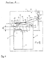
- the example described refers to an application of the invention in an electric circuit breaker of the gas type provided with a sealed enclosure 1 (shown diagrammatically in dashed lines) containing sulfur hexafluoride (SF 6 ) under pressure.
- this gas ensures the dielectric isolation of the circuit breaker.
- the gas pressure is brought to a nominal value P 0 .
- the value of the pressure in the enclosure 1 is monitored by means of a visual indicator device 2, disposed entirely inside the enclosure 1 and arranged to reveal, behind a transparent window (not shown) of the enclosure 1, a green indicating member 3 or a red indicating member 4 depending on whether the pressure P in this enclosure is higher or lower than a threshold pressure P 1 .
- the device comprises a sealed bellows cell 5, immersed in the gas inside the enclosure 1 and the lower end 6 of which is fixed to a stationary frame 7 which also guides the vertical movement of the cell. 5.
- the upper end of this cell is formed by a horizontal support plate 8 which rises or falls depending on whether the pressure in the enclosure decreases or increases.
- These vertical movements of the plate 8 are transmitted to the indicator member 3 by a toggle mechanism 10 described in detail below.
- a stop 11 can be provided on the frame 10 to limit the stroke 12 of the plate 8 and the bellows.
- the toggle mechanism 10 essentially comprises a link 13, a rocking lever 14 carried by the link and a spring 15 for holding in position intended to actuate said rocking lever.
- a first end 16 of the link 13 is pivotally mounted around a horizontal axis on the frame 7, by means of two pins 17 which could be replaced by a through axis.
- the link 13 has the shape of a fork, with two similar parallel arms 18 connected by a base 19 in the vicinity of said first end 16.
- the other end 20 of the link is rounded and rests on the plate 8 of the bellows cell 5.
- the two arms 18 have a bent shape and carry, near the elbow, pins 21 defining an axis of articulation 22 parallel to that of the pins 17 and serving as support and articulation to one end 23 of the rocking lever 14.
- This end 23 is disposed inside the fork of the link 13 and is pivotally mounted on the hinge pin 22, thanks to two longitudinal notches 24 fitted on the pins 21.
- This end 23 of the pivoting lever 14 also has a forked shape, to create a central clearance allowing to house the retaining spring 15.
- the ends of the latter are hooked on the one hand at an anchoring point 25 on the frame 7 and on the other hand at an application point 26 of a restoring force exerted on the rocking lever 14.
- the other end 27 of this lever is linked to the indicator member 3 by through a bent arm 28 having a finger 29 engaged in an oblong hole 30 of said rocking lever 14.
- the indicator member 3 is a tubular element which slides along a vertical cylindrical rod 31 fixed to the frame 7.
- the other indicator member 4 can be constituted by a part of the rod 31, colored red and masked, when the pressure in the enclosure is greater than the threshold pressure, by the green indicator member 3 in the position illustrated in Figure 1.
- This position is defined by a stop 32 disposed on the frame 7 to retain the rocking lever 14.
- this stop is not far from the end 27 of this lever, so that the latter and the indicator member 3 remain practically stationary when the pressure varies within the admissible limits.
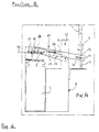
- the base 19 of the link 13 serves as a stop for the rocking lever 14 in an alert position represented by FIG. 4, that is to say when the indicator member 3 is not visible. It could however be replaced by a stop fixed to the frame.
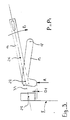
- the device described above operates in the following manner. As long as the pressure P of the gas inside the enclosure 1 is close to the nominal pressure, or at least has not dropped below a value equal to the alert threshold P 1 , the member indicator is in the normal position illustrated in Figure 1, marked by the presence of the green indicator member 3 behind the window of the enclosure. Small fluctuations in pressure around the nominal value can occur and cause the support plate 8 to go up and down and the hinge pin 22 of the levers 13 and 14 without significantly changing the position of the indicator member 3, as long as the axis 22 remains below an action line 33 defined as the straight line passing through the anchoring point 25 and the point of application 26 of the restoring force exerted by the spring 15 on the tilting lever 14. The return force of the spring 15 keeps the tilting lever 14 in abutment against the upper stop 32 and the link 13 in abutment against the surface 8 of the cell 5.
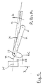
- the hinge pin 22 descending along arrow C crosses the line of action 33 and the spring 15 causes the rocking lever 14 to tilt upwards according to arrow D by raising the green indicator member 3 up to 'at its initial position shown in Figure 1.
- the two different pressure thresholds P 1 and P 2 correspond to different strokes D 1 and D2 of the support plate 8 relative to the frame 7. These values are therefore determined by the kinematics of the toggle mechanism. They can be adjusted by geometric adjustments of this mechanism, for example an adjustment of the position of the stops 32 and 19 and / or of the anchor point 25 of the spring.
- the metal bellows 5 is advantageously closed at its two opposite ends so as to be sealed with a perfect seal between its internal volume and the interior of the enclosure 1.
- the spring 15 could be replaced by a gravity device.
- the articulation 22 could be mounted directly on the plate 8 of the pressure sensor.
- the visual indicator composed of the members 3 and 4 could be replaced by any type of indicator comprising a movable element, coupled in any way with the rocking lever.
Landscapes
- Measuring Fluid Pressure (AREA)
- Fuel Cell (AREA)
Applications Claiming Priority (2)
| Application Number | Priority Date | Filing Date | Title |
|---|---|---|---|
| FR9504063 | 1995-03-31 | ||
| FR9504063A FR2732460B1 (fr) | 1995-03-31 | 1995-03-31 | Dispositif indicateur bistable pour signaler une chute de pression d'un gaz dans une enceinte |
Publications (2)
| Publication Number | Publication Date |
|---|---|
| EP0735558A1 true EP0735558A1 (de) | 1996-10-02 |
| EP0735558B1 EP0735558B1 (de) | 2001-08-08 |
Family
ID=9477792
Family Applications (1)
| Application Number | Title | Priority Date | Filing Date |
|---|---|---|---|
| EP19960410019 Expired - Lifetime EP0735558B1 (de) | 1995-03-31 | 1996-03-08 | Bistabiler Indikator zum Anzeigen eines Druckabfalls eines Gases in einem Raum |
Country Status (4)
| Country | Link |
|---|---|
| EP (1) | EP0735558B1 (de) |
| DE (1) | DE69614293T2 (de) |
| ES (1) | ES2161999T3 (de) |
| FR (1) | FR2732460B1 (de) |
Cited By (1)
| Publication number | Priority date | Publication date | Assignee | Title |
|---|---|---|---|---|
| WO1997031414A1 (en) * | 1996-02-26 | 1997-08-28 | Abb Transmit Oy | Method and arrangement for low-pressure locking of a gas-filled device |
Citations (10)
| Publication number | Priority date | Publication date | Assignee | Title |
|---|---|---|---|---|
| FR716249A (fr) * | 1930-04-30 | 1931-12-17 | Thomson Houston Comp Francaise | Perfectionnements aux appareils de commande tels que les appareils automatiques à contact |
| US2545056A (en) * | 1947-08-25 | 1951-03-13 | Honeywell Regulator Co | Control device |
| US2966566A (en) * | 1958-10-07 | 1960-12-27 | American District Telegraph Co | Signal transmitting apparatus |
| FR1364999A (fr) * | 1962-08-17 | 1964-06-26 | Micro Electric Ag | Dispositif formant interrupteur ou commutateur électrique ou analogue et ses diverses applications |
| US3157758A (en) * | 1962-03-19 | 1964-11-17 | Illinois Tool Works | Snap-action electric switch |
| CH403970A (de) * | 1963-03-01 | 1965-12-15 | Landis & Gyr Ag | Von einem Mengenzähler gesteuerter Schalter |
| EP0077981A2 (de) * | 1981-10-28 | 1983-05-04 | Siemens Aktiengesellschaft | Einrichtung zur Kontrolle der Dichte eines elektronegativen Gases in der Kapselung einer elektrischen Schaltanlage |
| DE3238530A1 (de) * | 1982-10-18 | 1984-04-26 | Franz Kirsten Elektrotechnische Spezialfabrik, 6530 Bingen | Schnappschalter |
| FR2637423A1 (fr) * | 1988-10-04 | 1990-04-06 | Merlin Gerin | Poste ou cellule electrique a isolement gazeux, equipe d'un dispositif de verrouillage a manque de pression de gaz |
| DE9106589U1 (de) * | 1991-05-29 | 1991-07-11 | ABB Patent GmbH, 6800 Mannheim | Temperaturkompensierter SF↓6↓-Dichtewächter |
-
1995
- 1995-03-31 FR FR9504063A patent/FR2732460B1/fr not_active Expired - Fee Related
-
1996
- 1996-03-08 EP EP19960410019 patent/EP0735558B1/de not_active Expired - Lifetime
- 1996-03-08 ES ES96410019T patent/ES2161999T3/es not_active Expired - Lifetime
- 1996-03-08 DE DE1996614293 patent/DE69614293T2/de not_active Expired - Fee Related
Patent Citations (10)
| Publication number | Priority date | Publication date | Assignee | Title |
|---|---|---|---|---|
| FR716249A (fr) * | 1930-04-30 | 1931-12-17 | Thomson Houston Comp Francaise | Perfectionnements aux appareils de commande tels que les appareils automatiques à contact |
| US2545056A (en) * | 1947-08-25 | 1951-03-13 | Honeywell Regulator Co | Control device |
| US2966566A (en) * | 1958-10-07 | 1960-12-27 | American District Telegraph Co | Signal transmitting apparatus |
| US3157758A (en) * | 1962-03-19 | 1964-11-17 | Illinois Tool Works | Snap-action electric switch |
| FR1364999A (fr) * | 1962-08-17 | 1964-06-26 | Micro Electric Ag | Dispositif formant interrupteur ou commutateur électrique ou analogue et ses diverses applications |
| CH403970A (de) * | 1963-03-01 | 1965-12-15 | Landis & Gyr Ag | Von einem Mengenzähler gesteuerter Schalter |
| EP0077981A2 (de) * | 1981-10-28 | 1983-05-04 | Siemens Aktiengesellschaft | Einrichtung zur Kontrolle der Dichte eines elektronegativen Gases in der Kapselung einer elektrischen Schaltanlage |
| DE3238530A1 (de) * | 1982-10-18 | 1984-04-26 | Franz Kirsten Elektrotechnische Spezialfabrik, 6530 Bingen | Schnappschalter |
| FR2637423A1 (fr) * | 1988-10-04 | 1990-04-06 | Merlin Gerin | Poste ou cellule electrique a isolement gazeux, equipe d'un dispositif de verrouillage a manque de pression de gaz |
| DE9106589U1 (de) * | 1991-05-29 | 1991-07-11 | ABB Patent GmbH, 6800 Mannheim | Temperaturkompensierter SF↓6↓-Dichtewächter |
Cited By (2)
| Publication number | Priority date | Publication date | Assignee | Title |
|---|---|---|---|---|
| WO1997031414A1 (en) * | 1996-02-26 | 1997-08-28 | Abb Transmit Oy | Method and arrangement for low-pressure locking of a gas-filled device |
| US6113065A (en) * | 1996-02-26 | 2000-09-05 | Abb Transmit Oy | Method and arrangement for low-pressure locking of a gas-filled device |
Also Published As
| Publication number | Publication date |
|---|---|
| ES2161999T3 (es) | 2001-12-16 |
| FR2732460B1 (fr) | 1997-05-09 |
| FR2732460A1 (fr) | 1996-10-04 |
| DE69614293D1 (de) | 2001-09-13 |
| DE69614293T2 (de) | 2002-05-23 |
| EP0735558B1 (de) | 2001-08-08 |
Similar Documents
| Publication | Publication Date | Title |
|---|---|---|
| EP0295158B1 (de) | Steuermechanismus eines elektrischen Kleinschalters | |
| EP0789380B1 (de) | Betätigungsmechanismus für einen Lastschalter mit durch einen kurzschlussentkuppelbare Verriegelung | |
| EP0452230B1 (de) | Antriebsmechanismus für Schutzschalter | |
| EP0224396B1 (de) | Steuermechanismus für Niederspannungslastschalter | |
| EP1542253B1 (de) | Anzeigeeinrichtung einer Auslöseeinrichtung eines elektrischen Schutzgeräts | |
| EP1743346B1 (de) | Überspannungsschutzeinrichtung mit lichtbogenlöschelementen | |
| EP0205361A1 (de) | Handbetätigte Schnapp-Schliesseinrichtung eines Miniaturschutzschalters | |
| EP0735558B1 (de) | Bistabiler Indikator zum Anzeigen eines Druckabfalls eines Gases in einem Raum | |
| EP0540398B1 (de) | Verbindungsbaugruppe vom Typ Schaltungsschleife | |
| EP2717284B1 (de) | Bedienungsvorrichtung eines elektrischen Schutzschaltgeräts, und diese umfassendes elektrisches Schutzschaltgerät | |
| FR2680911A1 (fr) | Sectionneur de terre a pouvoir de coupure. | |
| EP0798756B1 (de) | Betätigungsmechanismus für elektrischen Schutzschalter mit grossen Öffnungswinkel | |
| EP0657909A1 (de) | Elektrischer Schalter mit Fehlerauslosung | |
| FR2738667A1 (fr) | Interrupteur thermostatique | |
| FR2956922A1 (fr) | Dispositif de coupure | |
| EP0461027B1 (de) | Differential Auslösevorrichtung | |
| FR2665019A1 (fr) | Sectionneur a haute tension. | |
| CA2069185C (fr) | Dispositif d'insertion d'une varistance, incorpore dans un disjoncteur a haute tension | |
| FR3051593B1 (fr) | Dispositif de signalisation d'un defaut electrique dans un appareil de protection electrique, et appareil de protection electrique comportant un tel dispositif. | |
| EP0760524A1 (de) | Vorrichtung zum einstellen eines thermischen auslösers einer schutzschalter | |
| EP0032870B1 (de) | Auf ein Gestell montierbares Gerät zum Steuern der Bewegung eines Armes und Anwendung dieses Gerätes als Schalter | |
| EP0200581B1 (de) | Fehlerstromschutzschaltermechanismen die ihre Kupplung in oder an Selbstausschaltern erlauben | |
| CA1262268A (fr) | Systeme de signalisation a l'infrarouge pour detecter une condition predeteriminee d'un dispositif a haute tension | |
| FR2709371A1 (fr) | Appareil électrique fonctionnant en rupteur, en contacteur ou en inverseur. | |
| EP3232459B1 (de) | Elektrisches gerät zum leitungsschutz |
Legal Events
| Date | Code | Title | Description |
|---|---|---|---|
| PUAI | Public reference made under article 153(3) epc to a published international application that has entered the european phase |
Free format text: ORIGINAL CODE: 0009012 |
|
| AK | Designated contracting states |
Kind code of ref document: A1 Designated state(s): DE ES GB IE IT |
|
| 17P | Request for examination filed |
Effective date: 19970313 |
|
| RAP1 | Party data changed (applicant data changed or rights of an application transferred) |
Owner name: SCHNEIDER ELECTRIC INDUSTRIES SA |
|
| RAP1 | Party data changed (applicant data changed or rights of an application transferred) |
Owner name: SCHNEIDER ELECTRIC INDUSTRIES SA |
|
| GRAG | Despatch of communication of intention to grant |
Free format text: ORIGINAL CODE: EPIDOS AGRA |
|
| 17Q | First examination report despatched |
Effective date: 20001130 |
|
| GRAG | Despatch of communication of intention to grant |
Free format text: ORIGINAL CODE: EPIDOS AGRA |
|
| GRAH | Despatch of communication of intention to grant a patent |
Free format text: ORIGINAL CODE: EPIDOS IGRA |
|
| GRAH | Despatch of communication of intention to grant a patent |
Free format text: ORIGINAL CODE: EPIDOS IGRA |
|
| GRAA | (expected) grant |
Free format text: ORIGINAL CODE: 0009210 |
|
| AK | Designated contracting states |
Kind code of ref document: B1 Designated state(s): DE ES GB IE IT |
|
| REG | Reference to a national code |
Ref country code: IE Ref legal event code: FG4D Free format text: FRENCH |
|
| REF | Corresponds to: |
Ref document number: 69614293 Country of ref document: DE Date of ref document: 20010913 |
|
| GBT | Gb: translation of ep patent filed (gb section 77(6)(a)/1977) |
Effective date: 20011004 |
|
| REG | Reference to a national code |
Ref country code: ES Ref legal event code: FG2A Ref document number: 2161999 Country of ref document: ES Kind code of ref document: T3 |
|
| REG | Reference to a national code |
Ref country code: GB Ref legal event code: IF02 |
|
| PLBE | No opposition filed within time limit |
Free format text: ORIGINAL CODE: 0009261 |
|
| STAA | Information on the status of an ep patent application or granted ep patent |
Free format text: STATUS: NO OPPOSITION FILED WITHIN TIME LIMIT |
|
| 26N | No opposition filed | ||
| PGFP | Annual fee paid to national office [announced via postgrant information from national office to epo] |
Ref country code: DE Payment date: 20030303 Year of fee payment: 8 |
|
| PGFP | Annual fee paid to national office [announced via postgrant information from national office to epo] |
Ref country code: GB Payment date: 20030305 Year of fee payment: 8 |
|
| PGFP | Annual fee paid to national office [announced via postgrant information from national office to epo] |
Ref country code: IE Payment date: 20030327 Year of fee payment: 8 |
|
| PG25 | Lapsed in a contracting state [announced via postgrant information from national office to epo] |
Ref country code: IE Free format text: LAPSE BECAUSE OF NON-PAYMENT OF DUE FEES Effective date: 20040308 Ref country code: GB Free format text: LAPSE BECAUSE OF NON-PAYMENT OF DUE FEES Effective date: 20040308 |
|
| PG25 | Lapsed in a contracting state [announced via postgrant information from national office to epo] |
Ref country code: DE Free format text: LAPSE BECAUSE OF NON-PAYMENT OF DUE FEES Effective date: 20041001 |
|
| GBPC | Gb: european patent ceased through non-payment of renewal fee | ||
| REG | Reference to a national code |
Ref country code: IE Ref legal event code: MM4A |
|
| PGFP | Annual fee paid to national office [announced via postgrant information from national office to epo] |
Ref country code: ES Payment date: 20070417 Year of fee payment: 12 |
|
| PGFP | Annual fee paid to national office [announced via postgrant information from national office to epo] |
Ref country code: IT Payment date: 20070525 Year of fee payment: 12 |
|
| REG | Reference to a national code |
Ref country code: ES Ref legal event code: FD2A Effective date: 20080310 |
|
| PG25 | Lapsed in a contracting state [announced via postgrant information from national office to epo] |
Ref country code: ES Free format text: LAPSE BECAUSE OF NON-PAYMENT OF DUE FEES Effective date: 20080310 |
|
| PG25 | Lapsed in a contracting state [announced via postgrant information from national office to epo] |
Ref country code: IT Free format text: LAPSE BECAUSE OF NON-PAYMENT OF DUE FEES Effective date: 20080308 |