EP0736477A1 - Moteur d'entraînement pour ascenseur - Google Patents
Moteur d'entraînement pour ascenseur Download PDFInfo
- Publication number
- EP0736477A1 EP0736477A1 EP96301281A EP96301281A EP0736477A1 EP 0736477 A1 EP0736477 A1 EP 0736477A1 EP 96301281 A EP96301281 A EP 96301281A EP 96301281 A EP96301281 A EP 96301281A EP 0736477 A1 EP0736477 A1 EP 0736477A1
- Authority
- EP
- European Patent Office
- Prior art keywords
- machine
- wall
- base
- groove
- output shaft
- Prior art date
- Legal status (The legal status is an assumption and is not a legal conclusion. Google has not performed a legal analysis and makes no representation as to the accuracy of the status listed.)
- Granted
Links
- 238000005266 casting Methods 0.000 claims description 14
- 238000005520 cutting process Methods 0.000 claims description 10
- 238000004519 manufacturing process Methods 0.000 claims description 10
- 238000003754 machining Methods 0.000 claims description 9
- 238000000034 method Methods 0.000 claims description 7
- 229910001018 Cast iron Inorganic materials 0.000 claims description 5
- 229910000831 Steel Inorganic materials 0.000 claims description 5
- 239000000853 adhesive Substances 0.000 claims description 5
- 230000001070 adhesive effect Effects 0.000 claims description 5
- 230000035699 permeability Effects 0.000 claims description 5
- 239000010959 steel Substances 0.000 claims description 5
- 230000000712 assembly Effects 0.000 claims description 3
- 238000000429 assembly Methods 0.000 claims description 3
- 238000005553 drilling Methods 0.000 claims 5
- 239000000463 material Substances 0.000 claims 2
- 239000003822 epoxy resin Substances 0.000 description 3
- 239000002184 metal Substances 0.000 description 3
- 229910052751 metal Inorganic materials 0.000 description 3
- 229920000647 polyepoxide Polymers 0.000 description 3
- 239000007767 bonding agent Substances 0.000 description 2
- 230000004907 flux Effects 0.000 description 1
- 238000010348 incorporation Methods 0.000 description 1
- 150000002739 metals Chemical class 0.000 description 1
- 125000006850 spacer group Chemical group 0.000 description 1
Images

Classifications
-
- B—PERFORMING OPERATIONS; TRANSPORTING
- B66—HOISTING; LIFTING; HAULING
- B66B—ELEVATORS; ESCALATORS OR MOVING WALKWAYS
- B66B11/00—Main component parts of lifts in, or associated with, buildings or other structures
- B66B11/04—Driving gear ; Details thereof, e.g. seals
-
- F—MECHANICAL ENGINEERING; LIGHTING; HEATING; WEAPONS; BLASTING
- F16—ENGINEERING ELEMENTS AND UNITS; GENERAL MEASURES FOR PRODUCING AND MAINTAINING EFFECTIVE FUNCTIONING OF MACHINES OR INSTALLATIONS; THERMAL INSULATION IN GENERAL
- F16D—COUPLINGS FOR TRANSMITTING ROTATION; CLUTCHES; BRAKES
- F16D55/00—Brakes with substantially-radial braking surfaces pressed together in axial direction, e.g. disc brakes
- F16D55/24—Brakes with substantially-radial braking surfaces pressed together in axial direction, e.g. disc brakes with a plurality of axially-movable discs, lamellae, or pads, pressed from one side towards an axially-located member
- F16D55/26—Brakes with substantially-radial braking surfaces pressed together in axial direction, e.g. disc brakes with a plurality of axially-movable discs, lamellae, or pads, pressed from one side towards an axially-located member without self-tightening action
- F16D55/36—Brakes with a plurality of rotating discs all lying side by side
-
- B—PERFORMING OPERATIONS; TRANSPORTING
- B66—HOISTING; LIFTING; HAULING
- B66B—ELEVATORS; ESCALATORS OR MOVING WALKWAYS
- B66B11/00—Main component parts of lifts in, or associated with, buildings or other structures
- B66B11/04—Driving gear ; Details thereof, e.g. seals
- B66B11/043—Driving gear ; Details thereof, e.g. seals actuated by rotating motor; Details, e.g. ventilation
- B66B11/0446—Driving gear ; Details thereof, e.g. seals actuated by rotating motor; Details, e.g. ventilation with screw-nut or worm-screw gear
-
- F—MECHANICAL ENGINEERING; LIGHTING; HEATING; WEAPONS; BLASTING
- F16—ENGINEERING ELEMENTS AND UNITS; GENERAL MEASURES FOR PRODUCING AND MAINTAINING EFFECTIVE FUNCTIONING OF MACHINES OR INSTALLATIONS; THERMAL INSULATION IN GENERAL
- F16D—COUPLINGS FOR TRANSMITTING ROTATION; CLUTCHES; BRAKES
- F16D59/00—Self-acting brakes, e.g. coming into operation at a predetermined speed
- F16D59/02—Self-acting brakes, e.g. coming into operation at a predetermined speed spring-loaded and adapted to be released by mechanical, fluid, or electromagnetic means
-
- F—MECHANICAL ENGINEERING; LIGHTING; HEATING; WEAPONS; BLASTING
- F16—ENGINEERING ELEMENTS AND UNITS; GENERAL MEASURES FOR PRODUCING AND MAINTAINING EFFECTIVE FUNCTIONING OF MACHINES OR INSTALLATIONS; THERMAL INSULATION IN GENERAL
- F16D—COUPLINGS FOR TRANSMITTING ROTATION; CLUTCHES; BRAKES
- F16D2121/00—Type of actuator operation force
- F16D2121/18—Electric or magnetic
- F16D2121/20—Electric or magnetic using electromagnets
- F16D2121/22—Electric or magnetic using electromagnets for releasing a normally applied brake
-
- Y—GENERAL TAGGING OF NEW TECHNOLOGICAL DEVELOPMENTS; GENERAL TAGGING OF CROSS-SECTIONAL TECHNOLOGIES SPANNING OVER SEVERAL SECTIONS OF THE IPC; TECHNICAL SUBJECTS COVERED BY FORMER USPC CROSS-REFERENCE ART COLLECTIONS [XRACs] AND DIGESTS
- Y10—TECHNICAL SUBJECTS COVERED BY FORMER USPC
- Y10T—TECHNICAL SUBJECTS COVERED BY FORMER US CLASSIFICATION
- Y10T29/00—Metal working
- Y10T29/49—Method of mechanical manufacture
- Y10T29/4998—Combined manufacture including applying or shaping of fluent material
- Y10T29/49988—Metal casting
- Y10T29/49989—Followed by cutting or removing material
Definitions
- This invention relates to an elevator drive machine.
- Elevators are presently provided with a plurality of braking devices which are designed for use in normal operation of the elevator such as holding the cab in place when it stops at a landing and for use in emergency situations such as stopping the cab and/or counterweight from plunging into the hoistway pit.
- the normal operational brakes on geared elevator drive machines are typically drum brakes which engage the machine input shaft to hold the latter against rotation when the cab is stopped at a floor.
- Disc brakes have been added to provide braking on the output shaft.
- disc brakes on the output shaft were utilized in addition to input shaft brakes so that the elevator drive machine had both input shaft brakes and output shaft brakes.
- U S. Patent No. 5,226,508 discloses a disc-brake assembly for retrofit mounting to the output shaft and sheave of an existing elevator drive machine which has input shaft brakes.
- U.S. Patent No. 5,201,821 discloses a disc brake assembly for incorporation in new equipment elevator machines which have input shaft brakes.
- a preferred elevator drive machine has a machine housing with an outer wall, a rotatable output shaft with a sheave mounted on it for rotation therewith and a brake assembly for braking the output shaft and sheave.
- the brake assembly has a base integrally formed with the outer wall of the machine housing adjacent the output shaft.
- the machine housing may be a casting and the metal base of the brake assembly is cast or embedded within the casting of the outer wall of the housing.
- the outer wall of the machine housing is configured so that a predetermined portion of the casting of the outer wall forms the base of the brake assembly.
- the integrally formed base has a groove for housing the magnetic coil of a disc brake assembly.
- the base also has a plurality of bores for housing the brake springs and a plurality of bores for bolting the disc subassembly to the base.
- an outer wall segment of the drive machine housing is cast to form a base of the brake assembly.
- a metal blank of higher magnetic permeability is cast or embedded into the casting of the outer wall segment and is machined to form the base.
- the casting of the outer wall segment may be dimensioned and configured so that the casting of the counter wall segment itself forms the base.
- the outer wall segment is secured for machining a bearing assembly counterbore and, without unsecuring the wall segment from the machining operation, the base of the disc brake assembly is machined to form the groove for housing a magnetic coil, a plurality of bores to house the brake springs and a plurality of bolt bores. Precise relative alignment of the grooves, spring bores, stud bores, and bearing assembly counterbore is efficiently achieved by contemporaneous machining operations.
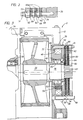
- a worm gear elevator drive machine is shown and generally designated by the numeral 10.
- the machine 10 generally comprises a machine or gear box housing 12, worm gear 14, worm wheel 16, output shaft 18 and drive sheave 20.
- the worm gear 14 meshes with the worm wheel 16 which is keyed directly to the output shaft 18.
- the shaft 18 is journaled in bearings 22, 24 mounted in the walls of the housing 12. It is understood that the worm gear 14 is driven by an electric motor (not shown) and in turn drives the worm wheel 16 and output shaft 18.
- the drive sheave 20 is mounted on and keyed to the output shaft 18 and carries the elevator and counterweight cables.
- a cover plate 26 is mounted on the end of the output shaft 18 to hold the sheave 20 in place on the shaft 18.
- the above described components are generally conventional to worm gear elevator drive assemblies.
- the machine 10 also includes an integrated disc brake assembly generally designated by the numeral 28 which comprises a base 30, a magnetic coil 32, an armature plate 34 and a disc subassembly 36.
- an integrated disc brake assembly generally designated by the numeral 28 which comprises a base 30, a magnetic coil 32, an armature plate 34 and a disc subassembly 36.
- the base 30 is integrally formed with the outer wall section 38 of the machine or gear box housing 12.
- the outer wall section 38 is cast iron and the base 30 is a steel blank which is cast or embedded directly into the wall section 38 and then machined into the configuration shown in Figure 1 as described in detail hereinafter.
- the bearings 24 are mounted within a counterbore 40 in the base 30.
- the bearings 24 are held in place in the counterbore 40 by a bearing retainer cover 41 which is fixed to the base 30 by bolts 42.
- a double lip seal 44 mounted to the cover 41 sealingly engages the output shaft 18 to seal the bearings 24.
- the base 30 has an outwardly opening U-shaped annular groove 46 concentric about the counterbore 40 and configured to house the magnetic coil 32.
- the base 30 also contains a plurality of threaded stud bores 48 for receiving studs 50, spring bores 52 for housing springs 54, and dowel bores 56 for receiving dowels 58 (shown in Figure 3).
- the magnetic coil 32 is bonded in the annular groove 46 by an adhesive or bonding agent such as an epoxy resin.
- the walls forming the groove are preferably rough cut to facilitate bonding of the coil within the groove 46.
- the coil 32 may be keyed to the groove 46 to lock the coil in place. Other types of suitable securement are also acceptable.
- the armature plate 34 is disposed adjacent the magnetic coil 32 and the disc subassembly 36.
- the disc subassembly 36 is bolted to the base 30 by four studs 50 and nuts 51 and comprises a plurality of interleaved friction discs 60 and brake plates 62.
- the outer part of each friction disc carries an annular radially outwardly extending friction pad 66.
- the friction discs 60 are mounted directly to the output shaft 18 for rotation by the shaft 18.
- the outer end of the shaft 18 has a plurality of axially extending splines 64 and the inner perimeters of the friction discs 60 are splined directly to the splines 64 so that the output shaft rotates the discs 60.
- the armature plate 34 is biased away from the magnetic coil 32 by a plurality of coil springs 54 mounted in base 30.
- the brake plates 62 are biased apart by a plurality of light coil springs 68 mounted on the studs 50 which extend through the armature plate 34 and the brake plates 62 ( Figure 2) .
- the brake plates 62 are thus held away from the interleaving friction discs 60 by the coil springs 68 when the brake assembly is "off".
- the nuts 51 are threaded onto the ends of the studs 50 so as to allow for adjustment of the spacing between the plates 62 to account for wear on the brake during its useful life.
- a plurality of guide dowels 58 dispersed circumferentially about the brake assembly 28 extend from the base 30 through the armature plate 34 and brake plates 62 to guide axial movement of these components relative to each other when the brake is set and released. It will be appreciated from the above that the discs 60 rotate with the output shaft and sheave 20, while the plates 62 remain relatively stationary.
- the brake assembly described above operates as follows. During normal safe operation of the elevator, the coil 32 is energized, and the armature plate 34 is magnetically held against the base 30 causing the actuating springs 54 to be compressed. The brake assembly 28 is thus in a "release" mode, and the friction discs 60 will be free to rotate with the shaft 18 uninhibited by the plates 62. When braking is required, such as in the event of an unsafe operating episode, e.g. the occurrence of overspeed in either direction, power to the coil 32 will be switched off, and the coil 32 will deenergize. The actuating springs 54 will then move the armature plate 34 away from the base 30 and toward the annular brake plates 62.
- the force of the springs 54 is such that the spacer springs 68 will be compressed and the plates 62 will clamp the discs 60 against further movement. Movement of the output shaft 18 and sheave 20 will thus be interrupted and the cab will stop its movement in the hoistway. At the same time, power to the machine will be interrupted.
- the brake assembly 28 can be released merely by restoring power to the coil 32.
- the brake assembly is similarly operable for normal braking as well as additional unsafe conditions such as to protect against uncontrolled. !ow speed movement of the elevator. Further general descriptions of the operation and structure of an elevator drive machine and disc brakes are found in the above-identified U.S. Patent 5,201,821 and U.S. Patent 5,226,508 which are incorporated herein by reference.
- the disc brake assembly is easily disassembled for servicing in the field by removal of the four nuts 51.
- the discs are splined directly to the outer end of the output shaft and no jacking of the output shaft is required to service the brake discs.
- Brake air gap adjustment is easy to accomplish using a feeler gauge and wrench. In this regard, an air gap of 0.5 mm is possible which greatly reduces the noise level due to normal operation of the brake.
- the outer wall segment 38 of housing 12 is cast iron and the integral base 30 is preferably steel for enhanced magnetic permeability. Other metals which provide acceptable magnetic permeability characteristics may also be utilized for the base 30.
- a steel blank for forming base 30 is cast or embedded directly into the wall segment 38 during the casting of wall segment 38.
- the wall segment 38 is then secured or bolted down for machining the bearing counterbore 40.
- the annular U-shaped groove 46 for housing the magnetic coil 32 is cut in the steel blank concentrically about the counterbore 40.
- the side walls of the U-shaped groove 46 are preferably rough cut to provide an enhanced bonding surface for the adhesive utilized in bonding the coil 32 within the groove 46.
- the stud bores 48, the spring bores 52, and the dowel bores 56 are drilled in the blank to form the base 30.
- the wall section 38 is then unsecured and removed from the cutting machine and thereafter the magnetic coil is fitted within the groove 46 and bonded in place by a suitable adhesive or bonding agent such as an epoxy resin.
- the preferred method of fabrication is to insert the magnetic coil into groove 46 and coat the magnetic coil with epoxy resin and cause it to cure thereby bonding the coil in the groove.
- the blank for forming base 30 may be omitted and the outer wall portion 38 is cast to a predetermined configuration to form a base for the disc brake assembly.
- the cast iron wall section 38 would form the base 30 and would be machined as described above to provide the annular groove 46, the threaded stud bores 48, the spring bores 52, the dowel bores 56 and the bearing counterbore 40.
- the dimensions and configuration of the base 30 will be determined so as to provide an acceptable magnetic flux path through the cast iron base 30.
- an integrated brake assembly according to the present invention is shown in a helical gear elevator drive machine generally designated by the numeral 11.
- the elevator drive machine 11 has a helical gear drive assembly 74 (not shown in detail) driving an output shaft 76 with a sheave 20 simply supported by bearing assemblies 78, 80 disposed on opposite sides of the sheave 20.
- the housing 12 of machine 11 includes an outer wall segment 38 referred to as a bearing stand. Similar to machine 10, the base 30 is integrally formed in the wall segment 38.
- the base 30 has a bearing counterbore 40 housing the bearing assembly 80.
- a retaining nut 82 is threadably mounted on the output shaft 76 to hold the bearing assembly 80 in the counterbore 40.
- An annular seal 84 is mounted on the armature plate 34 and sealingly engages the outer circumferal surface of the retaining nut 82 to seal the bearing assembly 80.
- the remaining components as indicated by identifying numerals in Figure 3 are similarly configured and assembled as described in relation to Figure 1 and need not be described in further detail for purposes of the alternative embodiment.
- the wall segment 38 and the base 30 are integrally formed and fabricated in accordance with the above-described method of fabrication.
- the integrated disc brake as already described may also be utilized in a gearless elevator drive machine having a simply supported sheave as illustrated in the drive machine 11 of Figure 3.
- the present invention provides a new and improved elevator-drive machine having output shaft braking without input shaft braking; and furthermore provides an integrated elevator drive machine and output shaft brake assembly; and further provides such an integrated brake assembly which is cost efficient to manufacture and reduces the number of component parts; and furthermore provides such a brake assembly which is easy and convenient to service; and furthermore provides a new and improved method of manufacture of such an integrated brake assembly; and furthermore provides an integrated disc brake assembly and method of manufacture that may be utilized in both worm gear and helical gear elevator drive machines as well as gearless elevator drive machines.
Landscapes
- Engineering & Computer Science (AREA)
- General Engineering & Computer Science (AREA)
- Mechanical Engineering (AREA)
- Civil Engineering (AREA)
- Structural Engineering (AREA)
- Physics & Mathematics (AREA)
- Electromagnetism (AREA)
- Cage And Drive Apparatuses For Elevators (AREA)
- Braking Arrangements (AREA)
- Elevator Control (AREA)
Applications Claiming Priority (2)
| Application Number | Priority Date | Filing Date | Title |
|---|---|---|---|
| US08/415,829 US5669469A (en) | 1995-04-03 | 1995-04-03 | Integrated elevator drive machine and brake assembly |
| US415829 | 1995-04-03 |
Publications (2)
| Publication Number | Publication Date |
|---|---|
| EP0736477A1 true EP0736477A1 (fr) | 1996-10-09 |
| EP0736477B1 EP0736477B1 (fr) | 2002-05-29 |
Family
ID=23647376
Family Applications (1)
| Application Number | Title | Priority Date | Filing Date |
|---|---|---|---|
| EP96301281A Expired - Lifetime EP0736477B1 (fr) | 1995-04-03 | 1996-02-26 | Moteur d'entraínement pour ascenseur |
Country Status (12)
| Country | Link |
|---|---|
| US (2) | US5669469A (fr) |
| EP (1) | EP0736477B1 (fr) |
| JP (1) | JPH08310748A (fr) |
| KR (1) | KR960037549A (fr) |
| CN (1) | CN1065211C (fr) |
| AU (1) | AU696150B2 (fr) |
| BR (1) | BR9601220A (fr) |
| CA (1) | CA2171519A1 (fr) |
| DE (1) | DE69621369T2 (fr) |
| ES (1) | ES2177723T3 (fr) |
| TW (1) | TW448127B (fr) |
| ZA (1) | ZA961648B (fr) |
Cited By (8)
| Publication number | Priority date | Publication date | Assignee | Title |
|---|---|---|---|---|
| KR960037549A (ko) * | 1995-04-03 | 1996-11-19 | 로버트 피이 헤이터 | 일체형 승강기 구동장치용 브레이크 조립체 및 그 제조 방법 |
| EP1279638A1 (fr) * | 2001-07-26 | 2003-01-29 | A. Friedr. Flender GmbH | Réducteur pour ascenseur |
| EP0967173A3 (fr) * | 1998-06-26 | 2004-01-02 | Kabushiki Kaisha Kobe Seiko Sho | Treuil hydraulique |
| WO2005049473A1 (fr) * | 2003-11-24 | 2005-06-02 | Kone Corporation | Frein et appareil de levage pour ascenseur |
| WO2006049612A1 (fr) * | 2004-11-01 | 2006-05-11 | Otis Elevator Company | Frein a disque d'ascenseur a amortissement |
| SG124253A1 (en) * | 1998-07-13 | 2006-08-30 | Inventio Ag | Rope traction elevator |
| FR2890499A1 (fr) * | 2005-09-05 | 2007-03-09 | Leroy Somer Moteurs | Machine electrique tournante |
| WO2011159282A1 (fr) * | 2010-06-15 | 2011-12-22 | Otis Elevator Company | Ensemble frein |
Families Citing this family (23)
| Publication number | Priority date | Publication date | Assignee | Title |
|---|---|---|---|---|
| US5950991A (en) * | 1997-05-06 | 1999-09-14 | Eaton Corporation | Force transmitting apparatus |
| US6675939B2 (en) * | 2001-01-31 | 2004-01-13 | Inertia Dynamics, Inc. | Elevator brake assembly |
| CA2472036A1 (fr) * | 2002-01-12 | 2003-07-31 | Otis Elevator Company | Frein d'ascenseur |
| US20060151254A1 (en) * | 2002-01-12 | 2006-07-13 | Jose Sevilleja-Perez | Elevator brake |
| JP3926695B2 (ja) * | 2002-07-24 | 2007-06-06 | 本田技研工業株式会社 | 電磁ブレーキ |
| DE10246588B4 (de) * | 2002-10-05 | 2006-02-02 | System Antriebstechnik Dresden Gmbh | Nothalte-Bremseinrichtung für Aufzugsmaschinen |
| FR2846163B1 (fr) * | 2002-10-18 | 2013-06-07 | Leroy Somer Moteurs | Machine comportant une poulie et un moteur electrique, notamment pour ascenseur |
| US7104367B2 (en) * | 2003-05-30 | 2006-09-12 | Warner Electric Europe S.A.S. | Modular and adaptable brake system for an elevator sheave |
| US20050133774A1 (en) * | 2003-12-03 | 2005-06-23 | Waupaca Elevator Company, Inc. | Drive-through force transmission device and methods |
| ZA200503649B (en) * | 2004-06-19 | 2006-02-22 | Inventio Ag | Drive for a lift installation. |
| US7763454B2 (en) * | 2004-07-09 | 2010-07-27 | Church & Dwight Co., Inc. | Electronic analyte assaying device |
| EP1795485A4 (fr) * | 2004-08-19 | 2011-07-27 | Mitsubishi Electric Corp | Dispositif de frein pour ascenseur |
| US8113318B2 (en) | 2006-08-15 | 2012-02-14 | Otis Elevator Company | Elevator machine with integrated brake surface |
| CA2646073C (fr) * | 2007-12-10 | 2011-02-01 | Rapid Egress Descent Systems Ltd. | Dispositif de commande de descente |
| US9016432B2 (en) | 2007-12-10 | 2015-04-28 | Rapid Egress Descent Systems Ltd. | Descent control device |
| US9856111B1 (en) | 2009-04-24 | 2018-01-02 | Paul Anderson | Elevator structure and brake system therefor |
| US9457988B1 (en) | 2009-04-24 | 2016-10-04 | Federal Equipment Company | Elevator structure and brake system therefor |
| US8752262B2 (en) * | 2009-12-22 | 2014-06-17 | Otis Elevator Company | Supplemental elevator brake and retrofitting installation procedure |
| CN103573969A (zh) * | 2012-07-18 | 2014-02-12 | 绍兴文理学院 | 一种刹车调整臂的蜗杆改良结构 |
| US9574625B2 (en) * | 2013-02-28 | 2017-02-21 | Atabec Safety Lock Corp. | Safety lock device for pump-jack |
| CN207078877U (zh) * | 2016-02-08 | 2018-03-09 | 刘伟强 | 一个无缆电梯系统 |
| CN113401772A (zh) * | 2016-06-15 | 2021-09-17 | 上海三菱电梯有限公司 | 电梯曳引机 |
| US20220112927A1 (en) * | 2019-10-25 | 2022-04-14 | Mcintosh Brake Systems, Llc | Brake system and method |
Citations (6)
| Publication number | Priority date | Publication date | Assignee | Title |
|---|---|---|---|---|
| US4436139A (en) * | 1981-07-20 | 1984-03-13 | Motor Wheel Corporation | Method and apparatus for manufacture of brake drums |
| US4684838A (en) * | 1985-07-26 | 1987-08-04 | Mavilor Systemes S.A. | Electric motor with deformable disk brake |
| JPH01133659A (ja) * | 1987-11-18 | 1989-05-25 | Jidosha Imono Kk | 車両用アクスルケースの製造方法 |
| US5121018A (en) * | 1991-03-04 | 1992-06-09 | Lucas Aerospace Power Equipment Corporation | Latching brake using permanent magnet |
| US5201821A (en) * | 1992-01-08 | 1993-04-13 | Otis Elevator Company | Disc brake elevator drive sheave |
| EP0541906A1 (fr) * | 1991-11-13 | 1993-05-19 | Jungheinrich Aktiengesellschaft | Frein à friction |
Family Cites Families (19)
| Publication number | Priority date | Publication date | Assignee | Title |
|---|---|---|---|---|
| US2214807A (en) * | 1940-05-01 | 1940-09-17 | Shepard Niles Crane & Hoist Co | Motor control and brake mechanism |
| US2461759A (en) * | 1945-02-26 | 1949-02-15 | Dumore Company | Alternating current brake motor |
| US2543830A (en) * | 1945-10-17 | 1951-03-06 | Standard Dayton Corp | Electromagnetic brake device |
| US2974756A (en) * | 1958-03-03 | 1961-03-14 | Reliance Electric & Eng Co | Automatic reset brake release |
| DE1575855A1 (de) * | 1966-12-16 | 1970-01-02 | Forster Electronic Gmbh | Magnet-Kupplung z.B. fuer Informationstraegergeraete,wie Lochkartentransportgeraete |
| US3642104A (en) * | 1968-08-22 | 1972-02-15 | Wolfgang Schafer | Electric couplings with permanent magnet |
| CH520285A (de) * | 1969-03-21 | 1972-03-15 | Baumueller Gmbh A | An einem Motorgehäuse angeordnete Einscheibenbremse zum Abbremsen der Motorwelle, insbesondere von Elektromotoren |
| US3752267A (en) * | 1971-12-07 | 1973-08-14 | Us Navy | Disc brake mechanism |
| CH599481A5 (fr) * | 1975-12-22 | 1978-05-31 | Inventio Ag | |
| US4476965A (en) * | 1982-08-09 | 1984-10-16 | Dana Corporation | Electromagnetic brake with cam release |
| US4606444A (en) * | 1983-08-03 | 1986-08-19 | Facet Enterprises, Inc. | Spring operated clutch |
| JPS61233231A (ja) * | 1985-04-09 | 1986-10-17 | Ogura Clutch Co Ltd | 負作動形電磁ブレ−キ |
| JPS6220921A (ja) * | 1985-07-19 | 1987-01-29 | Ogura Clutch Co Ltd | 負作動形電磁ブレ−キ |
| EP0328526B1 (fr) * | 1986-09-30 | 1991-12-11 | ZF FRIEDRICHSHAFEN Aktiengesellschaft | Boite de vitesses a frein integre pour vehicule |
| JPH0645430B2 (ja) * | 1988-12-07 | 1994-06-15 | 株式会社日立製作所 | エレベーター用巻上機のブレーキ装置及びそれを用いたエレベーター |
| US5101939A (en) * | 1990-04-13 | 1992-04-07 | Otis Elevator Company | Disk brake for elevator |
| US5202539A (en) * | 1991-08-28 | 1993-04-13 | Inventio Ag | Emergency brake apparatus for an elevator |
| US5226508A (en) * | 1991-12-02 | 1993-07-13 | Otis Elevator Company | Disc brake for elevator drive sheave |
| US5669469A (en) * | 1995-04-03 | 1997-09-23 | Otis Elevator Company | Integrated elevator drive machine and brake assembly |
-
1995
- 1995-04-03 US US08/415,829 patent/US5669469A/en not_active Expired - Fee Related
-
1996
- 1996-02-26 DE DE69621369T patent/DE69621369T2/de not_active Expired - Fee Related
- 1996-02-26 ES ES96301281T patent/ES2177723T3/es not_active Expired - Lifetime
- 1996-02-26 EP EP96301281A patent/EP0736477B1/fr not_active Expired - Lifetime
- 1996-02-29 ZA ZA961648A patent/ZA961648B/xx unknown
- 1996-03-04 AU AU45885/96A patent/AU696150B2/en not_active Ceased
- 1996-03-04 TW TW085102612A patent/TW448127B/zh not_active IP Right Cessation
- 1996-03-11 CA CA002171519A patent/CA2171519A1/fr not_active Abandoned
- 1996-03-12 US US08/614,432 patent/US5685059A/en not_active Expired - Fee Related
- 1996-04-01 BR BR9601220A patent/BR9601220A/pt not_active IP Right Cessation
- 1996-04-02 CN CN96103803A patent/CN1065211C/zh not_active Expired - Fee Related
- 1996-04-02 KR KR1019960009865A patent/KR960037549A/ko not_active Abandoned
- 1996-04-03 JP JP8081105A patent/JPH08310748A/ja not_active Withdrawn
Patent Citations (6)
| Publication number | Priority date | Publication date | Assignee | Title |
|---|---|---|---|---|
| US4436139A (en) * | 1981-07-20 | 1984-03-13 | Motor Wheel Corporation | Method and apparatus for manufacture of brake drums |
| US4684838A (en) * | 1985-07-26 | 1987-08-04 | Mavilor Systemes S.A. | Electric motor with deformable disk brake |
| JPH01133659A (ja) * | 1987-11-18 | 1989-05-25 | Jidosha Imono Kk | 車両用アクスルケースの製造方法 |
| US5121018A (en) * | 1991-03-04 | 1992-06-09 | Lucas Aerospace Power Equipment Corporation | Latching brake using permanent magnet |
| EP0541906A1 (fr) * | 1991-11-13 | 1993-05-19 | Jungheinrich Aktiengesellschaft | Frein à friction |
| US5201821A (en) * | 1992-01-08 | 1993-04-13 | Otis Elevator Company | Disc brake elevator drive sheave |
Non-Patent Citations (1)
| Title |
|---|
| PATENT ABSTRACTS OF JAPAN vol. 013, no. 380 (M - 863) 23 August 1989 (1989-08-23) * |
Cited By (13)
| Publication number | Priority date | Publication date | Assignee | Title |
|---|---|---|---|---|
| KR960037549A (ko) * | 1995-04-03 | 1996-11-19 | 로버트 피이 헤이터 | 일체형 승강기 구동장치용 브레이크 조립체 및 그 제조 방법 |
| EP0967173A3 (fr) * | 1998-06-26 | 2004-01-02 | Kabushiki Kaisha Kobe Seiko Sho | Treuil hydraulique |
| SG124253A1 (en) * | 1998-07-13 | 2006-08-30 | Inventio Ag | Rope traction elevator |
| EP1279638A1 (fr) * | 2001-07-26 | 2003-01-29 | A. Friedr. Flender GmbH | Réducteur pour ascenseur |
| WO2005049473A1 (fr) * | 2003-11-24 | 2005-06-02 | Kone Corporation | Frein et appareil de levage pour ascenseur |
| CN101052584B (zh) * | 2004-11-01 | 2011-06-08 | 奥蒂斯电梯公司 | 带阻尼的升降机盘式制动器 |
| US7699145B2 (en) | 2004-11-01 | 2010-04-20 | Otis Elevator Company | Elevator disk brake with damping |
| WO2006049612A1 (fr) * | 2004-11-01 | 2006-05-11 | Otis Elevator Company | Frein a disque d'ascenseur a amortissement |
| FR2890499A1 (fr) * | 2005-09-05 | 2007-03-09 | Leroy Somer Moteurs | Machine electrique tournante |
| US7538462B2 (en) | 2005-09-05 | 2009-05-26 | Moteurs Leroy-Somer | Electrical machine with rotating cable drive and integrated brake |
| WO2011159282A1 (fr) * | 2010-06-15 | 2011-12-22 | Otis Elevator Company | Ensemble frein |
| CN102933485A (zh) * | 2010-06-15 | 2013-02-13 | 奥的斯电梯公司 | 制动器组件 |
| EP2582607A4 (fr) * | 2010-06-15 | 2016-10-12 | Otis Elevator Co | Ensemble frein |
Also Published As
| Publication number | Publication date |
|---|---|
| US5669469A (en) | 1997-09-23 |
| TW448127B (en) | 2001-08-01 |
| KR960037549A (ko) | 1996-11-19 |
| JPH08310748A (ja) | 1996-11-26 |
| AU4588596A (en) | 1996-10-17 |
| ZA961648B (en) | 1996-07-11 |
| CN1065211C (zh) | 2001-05-02 |
| ES2177723T3 (es) | 2002-12-16 |
| DE69621369T2 (de) | 2003-03-06 |
| CN1150114A (zh) | 1997-05-21 |
| EP0736477B1 (fr) | 2002-05-29 |
| AU696150B2 (en) | 1998-09-03 |
| CA2171519A1 (fr) | 1996-10-04 |
| US5685059A (en) | 1997-11-11 |
| DE69621369D1 (de) | 2002-07-04 |
| BR9601220A (pt) | 1998-01-06 |
Similar Documents
| Publication | Publication Date | Title |
|---|---|---|
| EP0736477B1 (fr) | Moteur d'entraínement pour ascenseur | |
| KR100297198B1 (ko) | 엘리베이터드라이브시스템과그에결합된브레이크조립체 | |
| JP3422809B2 (ja) | エレベータ駆動綱車用ディスクブレーキ | |
| JP6405053B2 (ja) | エレベータ用巻上機及びエレベータ | |
| US20060151254A1 (en) | Elevator brake | |
| US5201821A (en) | Disc brake elevator drive sheave | |
| JP2016034872A (ja) | エレベータ用巻上機 | |
| CN1026723C (zh) | 电磁盘式制动器 | |
| JP5203371B2 (ja) | 複合材料製ブレーキハブを有するエレベータブレーキ | |
| JP5254232B2 (ja) | 一体的な軸受およびブレーキ面を備えるエレベータ巻上機ブレーキ | |
| CA2472036A1 (fr) | Frein d'ascenseur | |
| JP3617771B2 (ja) | エレベータ用巻上機 | |
| JP6606029B2 (ja) | エレベータ用巻上機、および、エレベータ装置 | |
| EP1845052B1 (fr) | Treuil d'ascenseur | |
| KR100824493B1 (ko) | 엘리베이터용 권상기 | |
| CN101941629B (zh) | 电梯驱动装置 | |
| JP2004189395A (ja) | エレベータ巻上機及びそのブレーキ装置 | |
| KR940007068Y1 (ko) | 주차전용빌딩의 주차설비 구동장치 제어용 전자브래이크 | |
| JP2013112502A (ja) | エレベーター用薄型巻上機 | |
| DE10136102A1 (de) | Getriebe für eine Aufzugsanlage | |
| HK1123270B (en) | Winding machine for elevator | |
| HK1123270A1 (zh) | 电梯用卷扬机 |
Legal Events
| Date | Code | Title | Description |
|---|---|---|---|
| PUAI | Public reference made under article 153(3) epc to a published international application that has entered the european phase |
Free format text: ORIGINAL CODE: 0009012 |
|
| AK | Designated contracting states |
Kind code of ref document: A1 Designated state(s): BE DE ES GB IT |
|
| 17P | Request for examination filed |
Effective date: 19961105 |
|
| GRAG | Despatch of communication of intention to grant |
Free format text: ORIGINAL CODE: EPIDOS AGRA |
|
| 17Q | First examination report despatched |
Effective date: 19981124 |
|
| GRAG | Despatch of communication of intention to grant |
Free format text: ORIGINAL CODE: EPIDOS AGRA |
|
| GRAG | Despatch of communication of intention to grant |
Free format text: ORIGINAL CODE: EPIDOS AGRA |
|
| GRAH | Despatch of communication of intention to grant a patent |
Free format text: ORIGINAL CODE: EPIDOS IGRA |
|
| ITF | It: translation for a ep patent filed | ||
| GRAH | Despatch of communication of intention to grant a patent |
Free format text: ORIGINAL CODE: EPIDOS IGRA |
|
| GRAA | (expected) grant |
Free format text: ORIGINAL CODE: 0009210 |
|
| AK | Designated contracting states |
Kind code of ref document: B1 Designated state(s): BE DE ES GB IT |
|
| REG | Reference to a national code |
Ref country code: GB Ref legal event code: FG4D |
|
| REF | Corresponds to: |
Ref document number: 69621369 Country of ref document: DE Date of ref document: 20020704 |
|
| REG | Reference to a national code |
Ref country code: ES Ref legal event code: FG2A Ref document number: 2177723 Country of ref document: ES Kind code of ref document: T3 |
|
| PG25 | Lapsed in a contracting state [announced via postgrant information from national office to epo] |
Ref country code: GB Free format text: LAPSE BECAUSE OF NON-PAYMENT OF DUE FEES Effective date: 20030226 |
|
| PG25 | Lapsed in a contracting state [announced via postgrant information from national office to epo] |
Ref country code: ES Free format text: LAPSE BECAUSE OF NON-PAYMENT OF DUE FEES Effective date: 20030227 |
|
| PG25 | Lapsed in a contracting state [announced via postgrant information from national office to epo] |
Ref country code: BE Free format text: LAPSE BECAUSE OF NON-PAYMENT OF DUE FEES Effective date: 20030228 |
|
| PLBE | No opposition filed within time limit |
Free format text: ORIGINAL CODE: 0009261 |
|
| STAA | Information on the status of an ep patent application or granted ep patent |
Free format text: STATUS: NO OPPOSITION FILED WITHIN TIME LIMIT |
|
| 26N | No opposition filed |
Effective date: 20030303 |
|
| PG25 | Lapsed in a contracting state [announced via postgrant information from national office to epo] |
Ref country code: DE Free format text: LAPSE BECAUSE OF NON-PAYMENT OF DUE FEES Effective date: 20030902 |
|
| GBPC | Gb: european patent ceased through non-payment of renewal fee | ||
| REG | Reference to a national code |
Ref country code: ES Ref legal event code: FD2A Effective date: 20030227 |
|
| PG25 | Lapsed in a contracting state [announced via postgrant information from national office to epo] |
Ref country code: IT Free format text: LAPSE BECAUSE OF NON-PAYMENT OF DUE FEES;WARNING: LAPSES OF ITALIAN PATENTS WITH EFFECTIVE DATE BEFORE 2007 MAY HAVE OCCURRED AT ANY TIME BEFORE 2007. THE CORRECT EFFECTIVE DATE MAY BE DIFFERENT FROM THE ONE RECORDED. Effective date: 20050226 |