EP0739786A2 - Volant incorporant un module à coussin d'air - Google Patents
Volant incorporant un module à coussin d'air Download PDFInfo
- Publication number
- EP0739786A2 EP0739786A2 EP96104159A EP96104159A EP0739786A2 EP 0739786 A2 EP0739786 A2 EP 0739786A2 EP 96104159 A EP96104159 A EP 96104159A EP 96104159 A EP96104159 A EP 96104159A EP 0739786 A2 EP0739786 A2 EP 0739786A2
- Authority
- EP
- European Patent Office
- Prior art keywords
- air bag
- steering wheel
- horn
- plate
- horn pad
- Prior art date
- Legal status (The legal status is an assumption and is not a legal conclusion. Google has not performed a legal analysis and makes no representation as to the accuracy of the status listed.)
- Granted
Links
Images



Classifications
-
- B—PERFORMING OPERATIONS; TRANSPORTING
- B60—VEHICLES IN GENERAL
- B60R—VEHICLES, VEHICLE FITTINGS, OR VEHICLE PARTS, NOT OTHERWISE PROVIDED FOR
- B60R21/00—Arrangements or fittings on vehicles for protecting or preventing injuries to occupants or pedestrians in case of accidents or other traffic risks
- B60R21/02—Occupant safety arrangements or fittings, e.g. crash pads
- B60R21/16—Inflatable occupant restraints or confinements designed to inflate upon impact or impending impact, e.g. air bags
- B60R21/20—Arrangements for storing inflatable members in their non-use or deflated condition; Arrangement or mounting of air bag modules or components
- B60R21/203—Arrangements for storing inflatable members in their non-use or deflated condition; Arrangement or mounting of air bag modules or components in steering wheels or steering columns
-
- B—PERFORMING OPERATIONS; TRANSPORTING
- B60—VEHICLES IN GENERAL
- B60Q—ARRANGEMENT OF SIGNALLING OR LIGHTING DEVICES, THE MOUNTING OR SUPPORTING THEREOF OR CIRCUITS THEREFOR, FOR VEHICLES IN GENERAL
- B60Q5/00—Arrangement or adaptation of acoustic signal devices
- B60Q5/001—Switches therefor
- B60Q5/003—Switches therefor mounted on the steering wheel
-
- B—PERFORMING OPERATIONS; TRANSPORTING
- B60—VEHICLES IN GENERAL
- B60R—VEHICLES, VEHICLE FITTINGS, OR VEHICLE PARTS, NOT OTHERWISE PROVIDED FOR
- B60R21/00—Arrangements or fittings on vehicles for protecting or preventing injuries to occupants or pedestrians in case of accidents or other traffic risks
- B60R21/02—Occupant safety arrangements or fittings, e.g. crash pads
- B60R21/16—Inflatable occupant restraints or confinements designed to inflate upon impact or impending impact, e.g. air bags
- B60R21/20—Arrangements for storing inflatable members in their non-use or deflated condition; Arrangement or mounting of air bag modules or components
- B60R21/201—Packaging straps or envelopes for inflatable members
Definitions
- the present invention relates to a steering wheel provided with an air bag device including a folded air bag and an inflator.
- the air bag device is disposed above a boss plate of a boss portion which is provided generally at the center of the steering wheel.
- a horn pad and a horn switch mechanism are provided above the air bag device.
- a typical example of a steering wheel includes a membrane switch buried therein (see, for example, Japanese Utility Model Publication Hei. 7-12209).
- This conventional steering wheel has an air bag device which includes an inflatable air bag and a pad which covers the air bag and which has an H-shaped tear line which is broken upon inflation of the air bag.
- the air bag is provided above a boss portion, and the pad has two membrane switches for horn operation.
- the air bag device is designed as follows.
- the inflator is combined with the folded air bag, and a cap-shaped horn pad is provided so that it surrounds the air bag which is mounted on the flange of the inflator.
- the air bag device is then mounted on the boss plate of the steering wheel from above with a supporting member coupled to the boss plate.
- a horn pad as an individual component separate from the core resin cover portion (made of, for example, soft urethane resin) of the steering wheel.
- a gap necessarily is formed between the core resin cover portion and the horn pad, that is, the former is separated from the latter, which impairs the front design of the steering wheel.
- the horn pad when the horn pad is depressed, it interferes with the upper surface of the air bag. That is, depressing the horn pad compresses the air bag. Hence, it is rather difficult for the operator to feel when the horn pad reaches the end of the horn operating stroke or when the horn is assuredly operated).
- the air bag device in combining the air bag device with a component such as a horn pad, the air bag is liable to be unfolded. Therefore, it is necessary to combine the air bag device with the component while holding the air bag, for instance, with the hand, so that it is maintained in its folded configuration. The installation of the air bag device is therefore inefficient and rather troublesome.
- a first object of the invention is to provide a steering wheel with an air bag device in which it is unnecessary to form the horn pad as an individual part, and in which the steering wheel and the horn pad appear unitary in front design. Therefore, the operator can feel when the horn pad comes to the end of the horn operating stroke.
- a second object of the invention is to provide a steering wheel provided with a horn having improved operability.
- a third object of the invention is to provide a steering wheel wherein the installation of an air bag device can be performed efficiently.
- an air bag device is provided above a boss plate of a boss portion provided at the center of the steering wheel.
- the air bag device includes a folded air bag and an inflator. Further, a horn pad and a horn switch mechanism are provided above the air bag device. The horn switch mechanism is operated by depressing the horn pad.
- the horn pad is integral with a core cover portion of a steering wheel body.
- a depressing plate is provided immediately below the horn pad, and the air bag device is fixedly secured to the boss plate.
- the depressing plate is substantially rigid and has a breakable tear line in the top wall thereof which is broken upon inflation of the air bag.
- the depressing plate is so shaped as to straddle the air bag. Also, elastic members resisting depression of the depressing plate and pairs of contacts of the horn switch mechanism are provided between the depressing plate and the boss plate.
- a membrane switch used in the horn switch mechanism may be provided immediately below the horn pad, and is operated by depressing the horn pad.
- the membrane switch is provided as a first assembly, combined with the air bag device.
- the air bag is held folded with an air bag embracing member which is shaped to straddle the air bag and be supported on the rear side of the air bag.
- the air bag embracing member includes a top wall which has a breakable part which is broken upon inflation of the air bag, and is substantially covered with the membrane switch, except for the breakable part.
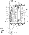
- an air bag device 19 is provided above a boss plate 13 of a boss portion 11, which is provided at the center of a steering wheel.
- the air bag device 19 includes a folded air bag 15, and an inflator 17.
- a horn pad 21 is provided above the air bag device 19.
- the first embodiment further includes a horn switch mechanism 23 which is operated by depressing the horn pad 21.
- the horn pad 21 is integral with a core cover portion 25 of a steering wheel body 10.
- a depressing plate 27 is provided immediately below the horn pad portion 21.
- the air bag device 19 is fixedly secured to the boss plate 13.
- the core cover portion 25 of the steering wheel includes a spoke portion S and a ring portion R.
- the core cover portion 25 is generally made of soft polyurethane foam resin or the like.
- the horn pad 21 has a thin breakable portion or tear line 21a which is broken upon inflation of the air bag.
- a configuration maintaining insert 29 is buried in the side wall of the horn pad 21, while a breakage preventing net insert 31 is buried in the top wall of the horn pad 21.
- the air bag device is mounted on the boss plate 13 with, for example, nuts 35 threadably engaged with a plurality of mounting bolts 33 (four bolts in the drawings) which extend downwardly from the flange 18 of the inflator 17.
- the boss plate 13 is cup-shaped in sectional view so as to accommodate the lower portion of the flange 18 of the inflator 17, and it is partially cut out to allow the nuts 35 to be threadably engaged with the bolts 33.
- the aforementioned depressing plate 27 is substantially rigid, and has a breakable groove (or a part to be broken) 27a in the top wall thereof which is broken when the air bag is inflated.
- the depressing plate 27 is substantially U-shaped in section so as to straddle the folded air bag 15.
- the depressing plate 27 shown in the figures is shaped like a laterally opened gate. However, it may also be in the form of a cylinder, for example.
- the depressing plate 27 is mounted on the boss plate 13 with a plurality of guide bolts 28 (four bolts 28 in the drawings).
- the depressing plate 27 is made from a hard plastic material, such as polyamide, which can be readily broken by a specifically applied force such as from the inflating airbag.
- the folded air bag is preferably compressed and bound with a sheet (or tape) 30 which can be readily broken upon inflation of the air bag.
- a pair of leaf springs 37 resisting the depression force of the depressing plate 27, and opposing pairs of contacts 39 and 41 of the horn switch mechanism are provided between the depressing plate 27 and the boss plate 13.
- the end portions of the two side walls of the depressing plate 27 are formed into flanges 27b and 27b.
- the pair of leaf springs 37 are curved downwardly, and are provided between the boss plate 13 and the two flanges 27b.
- the bottom of each of the downwardly curved leaf springs 37 is secured through an insulator 45 to the boss plate 13 with a rivet 38.
- the contacts 39 are formed, as movable contacts, on the lower surfaces of both end portions of each of the leaf springs 37.
- the contacts 41 are formed, as stationary contacts, on the boss plate 13. The pairs of contacts 39 and 41 are thus provided.
- coil springs may be mounted on the guide bolts 28, for example.
- the movable contacts 39 are formed directly on the flanges 27a of the depressing plate 27.
- the steering wheel of the invention is assembled as follows.
- the air bag device 19, including the folded air bag 15 and the inflator 17, is mounted by screws on the boss plate on which the horn switch mechanism 23, including the downwardly curved leaf springs 37, has been mounted.
- the depressing plate 27 is laid over the air bag 15.
- the depressing plate 27 is then mounted on the boss plate 13 with the guide bolts 28 so that it is vertically movable over a predetermined distance (i.e., the horn operating stroke).
- the assembly of the air bag device, the horn switch mechanism, and the boss plate is coupled to the steering wheel body 10 from below with screws 12. Thereafter, a lower cover 47 is mounted.
- the boss portion 11 is fitted on the serrated portion 51 of the steering shaft 49, and is then tightened with screws 53.
- the horn switch mechanism of the steering wheel thus assembled is operated by depression of the horn pad 21.
- the depression force applied to the horn pad 21 is transmitted through the depressing plate 27 located immediately below the horn pad 21 to the leaf springs 37. Therefore, the end portions of the leaf springs 37 are moved downwardly until the movable contacts 39 contact the stationary contacts 41.
- the horn switch mechanism is therefore actuated so as to blow the horn.
- the operator can positively feel through the fingers that the horn pad 21 has come to the end of the horn operating stroke.
- the steering wheel appears unitary in front design since the horn pad 21 is integral with a core cover portion 25 of a steering wheel body 10.
- a gap may be formed between the air bag 15 and the depressing plate 27.
- the gap is larger than the horn operating stroke. In this case, the problem is eliminated that, when the depressing plate 27 is depressed, the reaction force to compress the air bag 15 is applied through the depressing plate 27 to the operating portion of the horn pad 21. This feature further improves the operability of the horn pad 21.
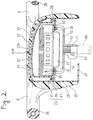
- a steering wheel with an air bag device of the second embodiment is similar to the first embodiment. However, a membrane switch 123 is provided immediately below the horn pad 21. The membrane switch 123 is operated by depression of the horn pad 21.
- the air bag device 19 and the membrane switch 123 are handled as one unit, that is, they are formed into a first assembly.
- the second embodiment is designed as follows.
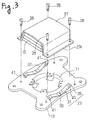
- the air bag 15 is held folded by an air bag embracing member 125 which straddles the air bag 15 and is supported on the rear side of the air bag 15 (as shown in Figs. 2 and 3).
- the air bag embracing member 125 has a breakable part 127 in its top wall which is broken upon inflation of the air bag.
- the air bag embracing member top wall, except the breakable part 127, is substantially covered with a membrane switch 123.
- the air bag embracing member 125 is substantially C-shaped in sectional view having a pair of legs 131 and 131.
- the end portion of each of the legs 131 is split into two parts, namely, mounting seats 133 and 133.
- Each of the mounting seats 133 has a mounting hole 133a.
- the air bag embracing member 125 may be formed by using a macromolecular elastic material such as a thermo-plastic elastomer which is able to maintain the configuration of the member.
- a hard plastic material such as polyamide, which is somewhat elastic, but is generally substantially rigid. This allows the operator to feel that the horn pad has come to the end of the horn operating stroke.
- the breakable part 127 in the top wall of the air bag embracing member is made up of a pair of slits. However, it may be formed by locally decreasing the thickness of the top wall, or it may comprise a line of small holes.
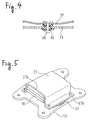
- the membrane switch 123 is made up of a pair of planar electrodes of polyester film with a gap between them which are short-circuited upon depression of the horn.
- the positive electrode of the membrane switch 123 is connected to a horn mechanism (not shown) through a first printed wire 135 formed on the front surface of the air bag embracing member 125 and through a lead wire 139 having a connector 137 at the end thereof.
- the negative electrode of the membrane switch 123 is ground to the boss plate 13 through a second printed wire 141 formed on the rear surface of the air bag embracing member 125 in such a manner that it extends to the mounting hole 133a.
- the horn pad 21 is so formed that it is integral with a core cover portion 25 of a steering wheel body 10, as in the first embodiment.
- the boss plate 13 can be combined with the first assembly of the air bag device 19 and the membrane switch 123. Accordingly, the boss plate 13 is provided as a second assembly which is combined with the first assembly, that is, the air bag device 19 and the membrane switch 123.
- the air bag device 19, the boss plate 13, and the membrane switch 23 are assembled as follows.
- a plurality of mounting bolts 129 (four mounting bolts, as shown), which extend downwardly from the flange 18 of the inflator 17 through the peripheral portion 15a of the air bag 15 which is provided around inflator setting holes, are inserted into air bag device mounting holes 13a formed in the boss plate 13.
- the air bag embracing member 125 is set over the air bag 15 with its two legs 131 being opened against their elastic forces.
- the mounting bolts 129 are then inserted into the mounting holes 133a of the mounting seats 133 of those legs 131.
- nuts are threadably engaged with the mounting bolts 129 thus inserted.
- the boss plate 13 is cup-shaped in sectional view so as to accommodate the lower portion of the flange 18 of the inflator 17, and it is partially cut to allow the aforementioned nuts to be threadably engaged with the bolts 29.
- the air bag device 19 and the membrane switch 123 may be assembled with each other in advance.
- the mounting seats 133 of the air bag embracing member 125 are held between the boss plate 13 and the flange 18 of the inflator 17, as viewed in the drawings.
- the steering wheel thus designed is assembled as follows.
- the assembly of the air bag device 19, the boss plate 13 and the air bag embracing member 25 (integral with the membrane switch 123) is combined with the steering wheel body 10 with which the horn pad is integral. That is, mounting screws 42 are screwed through mounting holes 13b formed in the boss plate 13 into mounting female-threaded holes 44a formed in the spoke core 44 of the steering wheel body 10. A serrated portion 51 of the boss portion 11 is fitted on the end portion of a steering shaft 49.
- mounting holes 46a of a lower cover 47 being aligned with mounting holes 43a of the steering wheel body 10, the lower cover 47 is secured to the steering wheel body 10 with screws (not shown).
- the horn switch mechanism of the steering wheel thus constructed is operated by depression of the horn pad 21.
- a depression force applied to the horn pad 21 is transmitted to the upper electrode (the positive electrode) of the membrane switch 123 provided below it, so that the upper electrode touches the lower electrode (the negative electrode). Therefore, the membrane switch 123 actuates the horn. Accordingly, the operator can positively feel through the fingers that the horn pad 21 has come to the end of the horn operating stroke since the air bag embracing member 125 is substantially rigid.
- the air bag device and the membrane switch can be provided as the first assembly with the air bag held folded. This feature contributes greatly to the improvement in installation of the air bag device and the membrane switch.
- the membrane switch in the above embodiment outputs electric current in accordance with depression of the horn pad.
- a membrane switch which can vary electric resistance, amount of electric current and dielectric constant thereof in accordance with depression of the horn pad.
Landscapes
- Engineering & Computer Science (AREA)
- Mechanical Engineering (AREA)
- Physics & Mathematics (AREA)
- Acoustics & Sound (AREA)
- Air Bags (AREA)
- Steering Controls (AREA)
Applications Claiming Priority (6)
| Application Number | Priority Date | Filing Date | Title |
|---|---|---|---|
| JP10433795 | 1995-04-27 | ||
| JP104337/95 | 1995-04-27 | ||
| JP7104337A JPH08295200A (ja) | 1995-04-27 | 1995-04-27 | エアバッグ装置付きステアリングホイール |
| JP11447095 | 1995-05-12 | ||
| JP114470/95 | 1995-05-12 | ||
| JP7114470A JPH08301052A (ja) | 1995-05-12 | 1995-05-12 | エアバッグ装置付きステアリングホイール |
Publications (4)
| Publication Number | Publication Date |
|---|---|
| EP0739786A2 true EP0739786A2 (fr) | 1996-10-30 |
| EP0739786A3 EP0739786A3 (fr) | 1997-09-17 |
| EP0739786B1 EP0739786B1 (fr) | 2001-01-17 |
| EP0739786B2 EP0739786B2 (fr) | 2003-05-21 |
Family
ID=26444834
Family Applications (1)
| Application Number | Title | Priority Date | Filing Date |
|---|---|---|---|
| EP96104159A Expired - Lifetime EP0739786B2 (fr) | 1995-04-27 | 1996-03-15 | Volant incorporant un module à coussin d'air |
Country Status (3)
| Country | Link |
|---|---|
| US (1) | US5727811A (fr) |
| EP (1) | EP0739786B2 (fr) |
| DE (1) | DE69611566T3 (fr) |
Cited By (4)
| Publication number | Priority date | Publication date | Assignee | Title |
|---|---|---|---|---|
| EP0783996A1 (fr) * | 1996-01-11 | 1997-07-16 | Morton International, Inc. | Ensemble de coussin gonflable comportant une poche pour contacteur d'avertisseur |
| EP0842826A1 (fr) * | 1996-11-19 | 1998-05-20 | Autoliv ASP, Inc. | Volant pour automobile avec coussin gonflable et commutateur de klaxon. |
| EP0842827A1 (fr) * | 1996-11-19 | 1998-05-20 | Autoliv ASP, Inc. | Module de coussin gonflable avec contacteur de klaxon fixé à une bande |
| US6942247B2 (en) * | 2003-03-12 | 2005-09-13 | Delphi Technologies, Inc. | Driver airbag formed contact spring |
Families Citing this family (22)
| Publication number | Priority date | Publication date | Assignee | Title |
|---|---|---|---|---|
| EP0728652B1 (fr) * | 1995-02-27 | 2003-05-14 | Toyoda Gosei Co., Ltd. | Procédé de fabrication d'un volant de direction et volant obtenu par ce procédé |
| JP3327104B2 (ja) * | 1996-03-27 | 2002-09-24 | 豊田合成株式会社 | ステアリングホイール |
| JPH106897A (ja) * | 1996-06-21 | 1998-01-13 | Toyoda Gosei Co Ltd | エアバッグ装置 |
| DE19714169C2 (de) * | 1997-03-21 | 2000-11-09 | Petri Ag | Anordnung zur Hupbetätigung bei Lenkrädern mit integriertem Airbagmodul |
| DE59809761D1 (de) * | 1997-04-16 | 2003-11-06 | Volkswagen Ag | Lenksäule für Insassenschutzeinrichtungen und Sicherheitslenkungen |
| DE29805207U1 (de) * | 1998-03-23 | 1998-06-04 | TRW Automotive Safety Systems GmbH, 63743 Aschaffenburg | Lenkrad mit Airbag |
| US6042143A (en) * | 1998-06-02 | 2000-03-28 | Breed Automotive Technology, Inc. | Integrated steering wheel with improved manufacturing capability |
| US6164691A (en) * | 1999-07-22 | 2000-12-26 | Breed Automotive Technology, Inc. | Steering wheel |
| US6386579B1 (en) * | 1999-07-22 | 2002-05-14 | Breed Automotive Technology, Inc. | Steering wheel |
| JP4581244B2 (ja) * | 2000-01-14 | 2010-11-17 | タカタ株式会社 | エアバッグ装置及びステアリングホイール |
| US6678767B1 (en) * | 2000-10-06 | 2004-01-13 | Broadcom Corp | Bus sampling on one edge of a clock signal and driving on another edge |
| US6578911B2 (en) * | 2000-11-30 | 2003-06-17 | Ts Tech Co., Ltd. | Seat provided with air bag module |
| DE20021532U1 (de) * | 2000-12-20 | 2001-04-26 | TRW Automotive Safety Systems GmbH & Co. KG, 63743 Aschaffenburg | Fahrzeuglenkrad |
| US6616181B1 (en) * | 2002-04-05 | 2003-09-09 | Breed Automotive Tedhnology, Inc. | Horn mechanism featuring immunity to cushion fold |
| US7159897B2 (en) * | 2003-07-21 | 2007-01-09 | Delphi Technologies, Inc. | Isolated ground for horn mechanism |
| DE102004037462A1 (de) * | 2004-08-03 | 2006-03-16 | Trw Automotive Safety Systems Gmbh & Co. Kg | Baugruppe mit Lenkrad und Gassackmodul |
| DE102005002945A1 (de) | 2005-01-18 | 2006-07-27 | Takata-Petri Ag | Generatorträger für ein Fahrerairbagmodul zum Einbauen in ein Lenkrad eines Kraftfahrzeuges |
| DE102008004984A1 (de) * | 2008-01-17 | 2009-09-10 | Paragon Ag | Auslösevorrichtung für eine Hupanlage eines Kraftfahrzeugs |
| JP5926631B2 (ja) * | 2012-06-27 | 2016-05-25 | タカタ株式会社 | エアバッグ装置及びエアバッグ装置の製造方法 |
| JP6274164B2 (ja) * | 2015-07-28 | 2018-02-07 | トヨタ自動車株式会社 | 運転席用エアバッグ装置 |
| DE102016117001B4 (de) | 2016-09-09 | 2023-05-17 | Autoliv Development Ab | Hupenaktivierungseinrichtung |
| DE102017217344B4 (de) | 2017-09-28 | 2023-12-07 | Joyson Safety Systems Germany Gmbh | Lenkrad für ein Kraftfahrzeug |
Family Cites Families (15)
| Publication number | Priority date | Publication date | Assignee | Title |
|---|---|---|---|---|
| US3819205A (en) * | 1972-09-25 | 1974-06-25 | Gen Motors Corp | Modular occupant restraint system |
| JPH02133955A (ja) * | 1988-11-15 | 1990-05-23 | Mitsubishi Electric Corp | 半導体集積回路装置 |
| US5004266A (en) † | 1990-05-23 | 1991-04-02 | General Motors Corporation | Occupant restraint system |
| US5085462A (en) * | 1990-06-29 | 1992-02-04 | Gualtier Quentin E | Airbag and vehicle horn switch assembly |
| JPH0818560B2 (ja) † | 1991-05-29 | 1996-02-28 | 日本プラスト株式会社 | ステアリングホイールのホーンスイッチ装置 |
| JP3163747B2 (ja) * | 1992-06-01 | 2001-05-08 | 豊田合成株式会社 | ステアリングホイールのパッド |
| JPH061246A (ja) * | 1992-06-23 | 1994-01-11 | Nippon Plast Co Ltd | ステアリングホイール |
| US5327796A (en) * | 1992-12-28 | 1994-07-12 | General Motors Corporation | Horn switch actuated by rocking air bag module |
| US5265905A (en) * | 1993-01-07 | 1993-11-30 | Ford Motor Company | Air bag cover horn blow switch assembly |
| JPH06239242A (ja) * | 1993-02-16 | 1994-08-30 | Taisei Plus Kk | 警笛スイッチ付エアバック用カバー |
| JP2610383B2 (ja) * | 1993-02-19 | 1997-05-14 | 日本プラスト株式会社 | ステアリングホイール |
| JPH06312643A (ja) * | 1993-04-30 | 1994-11-08 | Tokai Rika Co Ltd | エアバッグ装置付きステアリング装置 |
| JP3085028B2 (ja) * | 1993-06-28 | 2000-09-04 | 日産自動車株式会社 | 自動変速機の変速制御装置 |
| AU7941794A (en) † | 1993-10-15 | 1995-05-04 | Gersteen | Steering wheel for motor vehicles, mounting component and steering column cooperating with said steering wheel, and method of manufacture |
| JP3273679B2 (ja) * | 1993-11-19 | 2002-04-08 | 日本プラスト株式会社 | ステアリングホイール |
-
1996
- 1996-03-15 EP EP96104159A patent/EP0739786B2/fr not_active Expired - Lifetime
- 1996-03-15 US US08/616,269 patent/US5727811A/en not_active Expired - Fee Related
- 1996-03-15 DE DE69611566T patent/DE69611566T3/de not_active Expired - Fee Related
Cited By (5)
| Publication number | Priority date | Publication date | Assignee | Title |
|---|---|---|---|---|
| EP0783996A1 (fr) * | 1996-01-11 | 1997-07-16 | Morton International, Inc. | Ensemble de coussin gonflable comportant une poche pour contacteur d'avertisseur |
| EP1088713A1 (fr) * | 1996-01-11 | 2001-04-04 | Autoliv Asp, Inc. | Ensemble de coussin gonflable comportant une poche pour contacteur |
| EP0842826A1 (fr) * | 1996-11-19 | 1998-05-20 | Autoliv ASP, Inc. | Volant pour automobile avec coussin gonflable et commutateur de klaxon. |
| EP0842827A1 (fr) * | 1996-11-19 | 1998-05-20 | Autoliv ASP, Inc. | Module de coussin gonflable avec contacteur de klaxon fixé à une bande |
| US6942247B2 (en) * | 2003-03-12 | 2005-09-13 | Delphi Technologies, Inc. | Driver airbag formed contact spring |
Also Published As
| Publication number | Publication date |
|---|---|
| EP0739786B2 (fr) | 2003-05-21 |
| EP0739786B1 (fr) | 2001-01-17 |
| EP0739786A3 (fr) | 1997-09-17 |
| DE69611566T2 (de) | 2001-08-23 |
| DE69611566D1 (de) | 2001-02-22 |
| US5727811A (en) | 1998-03-17 |
| DE69611566T3 (de) | 2004-04-08 |
Similar Documents
| Publication | Publication Date | Title |
|---|---|---|
| US5727811A (en) | Steering wheel with air bag device | |
| US5085462A (en) | Airbag and vehicle horn switch assembly | |
| US5198629A (en) | Steering wheel having insert molded membrane switch | |
| EP0572125B1 (fr) | Interrupteur d'avertisseur central dans un module de sac gonflable pour conducteur de véhicule | |
| US5909804A (en) | Depression activated switch | |
| JP3040525U (ja) | 車両の膨張型乗員拘束モジュールのハウジングを車両の操舵ハンドル支持体に装着するための装着装置、車両の膨張型乗員拘束モジュールと該モジュールを操舵ハンドル支持体に装着するための装着装置との組み合わせ、及び車両の膨張型乗員拘束モジュールのハウジングを車両の操舵ハンドル支持体に装着するための弾性圧縮可能な部材 | |
| EP0669229B1 (fr) | Commutateur à membrane | |
| US5767466A (en) | Flexible switch for a vehicle steering wheel assembly | |
| EP1591326A2 (fr) | Dispositif de direction | |
| US5723834A (en) | Horn membrane switch with rupturable strain relief bridging connector | |
| JPS587556Y2 (ja) | 絵表示スイツチ | |
| CA1154000A (fr) | Clavier et mode de realisation | |
| EP1669255A1 (fr) | Actionneur de klaxon, système de sac gonflable et volant | |
| US20040090052A1 (en) | Airbag apparatus | |
| EP1492686B1 (fr) | Coussin d'air avec mecanisme d'avertisseur sonore sans risque | |
| JPH08295200A (ja) | エアバッグ装置付きステアリングホイール | |
| JPH08318806A (ja) | 運転席用エアバッグモジュール | |
| EP0910521B1 (fr) | Dispositif pour volant de vehicule | |
| JP4046643B2 (ja) | ステアリングホイールのホーンスイッチ装置 | |
| US10493942B2 (en) | Device for operating horn of vehicle | |
| JP3468146B2 (ja) | 車両のエアバッグモジュール | |
| JPH10119789A (ja) | ステアリングホイール | |
| US20020195325A1 (en) | Membrane switch for floater modules | |
| JPH08301052A (ja) | エアバッグ装置付きステアリングホイール | |
| JP2588855Y2 (ja) | グリップスイッチ |
Legal Events
| Date | Code | Title | Description |
|---|---|---|---|
| PUAI | Public reference made under article 153(3) epc to a published international application that has entered the european phase |
Free format text: ORIGINAL CODE: 0009012 |
|
| 17P | Request for examination filed |
Effective date: 19960315 |
|
| AK | Designated contracting states |
Kind code of ref document: A2 Designated state(s): DE FR GB |
|
| PUAL | Search report despatched |
Free format text: ORIGINAL CODE: 0009013 |
|
| AK | Designated contracting states |
Kind code of ref document: A3 Designated state(s): DE FR GB |
|
| 17Q | First examination report despatched |
Effective date: 19990305 |
|
| GRAG | Despatch of communication of intention to grant |
Free format text: ORIGINAL CODE: EPIDOS AGRA |
|
| GRAG | Despatch of communication of intention to grant |
Free format text: ORIGINAL CODE: EPIDOS AGRA |
|
| GRAH | Despatch of communication of intention to grant a patent |
Free format text: ORIGINAL CODE: EPIDOS IGRA |
|
| GRAH | Despatch of communication of intention to grant a patent |
Free format text: ORIGINAL CODE: EPIDOS IGRA |
|
| GRAA | (expected) grant |
Free format text: ORIGINAL CODE: 0009210 |
|
| AK | Designated contracting states |
Kind code of ref document: B1 Designated state(s): DE FR GB |
|
| REF | Corresponds to: |
Ref document number: 69611566 Country of ref document: DE Date of ref document: 20010222 |
|
| ET | Fr: translation filed | ||
| PLBQ | Unpublished change to opponent data |
Free format text: ORIGINAL CODE: EPIDOS OPPO |
|
| PLBI | Opposition filed |
Free format text: ORIGINAL CODE: 0009260 |
|
| PLBF | Reply of patent proprietor to notice(s) of opposition |
Free format text: ORIGINAL CODE: EPIDOS OBSO |
|
| 26 | Opposition filed |
Opponent name: AUTOLIV DEVELOPMENT AB Effective date: 20011017 |
|
| REG | Reference to a national code |
Ref country code: GB Ref legal event code: IF02 |
|
| PLBF | Reply of patent proprietor to notice(s) of opposition |
Free format text: ORIGINAL CODE: EPIDOS OBSO |
|
| PLAW | Interlocutory decision in opposition |
Free format text: ORIGINAL CODE: EPIDOS IDOP |
|
| PLAW | Interlocutory decision in opposition |
Free format text: ORIGINAL CODE: EPIDOS IDOP |
|
| PUAH | Patent maintained in amended form |
Free format text: ORIGINAL CODE: 0009272 |
|
| STAA | Information on the status of an ep patent application or granted ep patent |
Free format text: STATUS: PATENT MAINTAINED AS AMENDED |
|
| 27A | Patent maintained in amended form |
Effective date: 20030521 |
|
| AK | Designated contracting states |
Designated state(s): DE FR GB |
|
| PGFP | Annual fee paid to national office [announced via postgrant information from national office to epo] |
Ref country code: GB Payment date: 20040310 Year of fee payment: 9 |
|
| ET3 | Fr: translation filed ** decision concerning opposition | ||
| PGFP | Annual fee paid to national office [announced via postgrant information from national office to epo] |
Ref country code: FR Payment date: 20050308 Year of fee payment: 10 |
|
| PG25 | Lapsed in a contracting state [announced via postgrant information from national office to epo] |
Ref country code: GB Free format text: LAPSE BECAUSE OF NON-PAYMENT OF DUE FEES Effective date: 20050315 |
|
| GBPC | Gb: european patent ceased through non-payment of renewal fee |
Effective date: 20050315 |
|
| REG | Reference to a national code |
Ref country code: FR Ref legal event code: ST Effective date: 20061130 |
|
| PG25 | Lapsed in a contracting state [announced via postgrant information from national office to epo] |
Ref country code: FR Free format text: LAPSE BECAUSE OF NON-PAYMENT OF DUE FEES Effective date: 20060331 |
|
| PGFP | Annual fee paid to national office [announced via postgrant information from national office to epo] |
Ref country code: DE Payment date: 20080313 Year of fee payment: 13 |
|
| PG25 | Lapsed in a contracting state [announced via postgrant information from national office to epo] |
Ref country code: DE Free format text: LAPSE BECAUSE OF NON-PAYMENT OF DUE FEES Effective date: 20091001 |