EP0739858A2 - Flüssigkeitsabscheider und Filter dafür - Google Patents
Flüssigkeitsabscheider und Filter dafür Download PDFInfo
- Publication number
- EP0739858A2 EP0739858A2 EP96201160A EP96201160A EP0739858A2 EP 0739858 A2 EP0739858 A2 EP 0739858A2 EP 96201160 A EP96201160 A EP 96201160A EP 96201160 A EP96201160 A EP 96201160A EP 0739858 A2 EP0739858 A2 EP 0739858A2
- Authority
- EP
- European Patent Office
- Prior art keywords
- liquid
- contaminants
- recited
- separating
- hydrocarbon
- Prior art date
- Legal status (The legal status is an assumption and is not a legal conclusion. Google has not performed a legal analysis and makes no representation as to the accuracy of the status listed.)
- Withdrawn
Links
Images




Classifications
-
- B—PERFORMING OPERATIONS; TRANSPORTING
- B01—PHYSICAL OR CHEMICAL PROCESSES OR APPARATUS IN GENERAL
- B01D—SEPARATION
- B01D17/00—Separation of liquids, not provided for elsewhere, e.g. by thermal diffusion
-
- B—PERFORMING OPERATIONS; TRANSPORTING
- B01—PHYSICAL OR CHEMICAL PROCESSES OR APPARATUS IN GENERAL
- B01D—SEPARATION
- B01D17/00—Separation of liquids, not provided for elsewhere, e.g. by thermal diffusion
- B01D17/02—Separation of non-miscible liquids
- B01D17/0202—Separation of non-miscible liquids by ab- or adsorption
-
- B—PERFORMING OPERATIONS; TRANSPORTING
- B01—PHYSICAL OR CHEMICAL PROCESSES OR APPARATUS IN GENERAL
- B01D—SEPARATION
- B01D17/00—Separation of liquids, not provided for elsewhere, e.g. by thermal diffusion
- B01D17/02—Separation of non-miscible liquids
- B01D17/0208—Separation of non-miscible liquids by sedimentation
- B01D17/0211—Separation of non-miscible liquids by sedimentation with baffles
-
- B—PERFORMING OPERATIONS; TRANSPORTING
- B01—PHYSICAL OR CHEMICAL PROCESSES OR APPARATUS IN GENERAL
- B01D—SEPARATION
- B01D17/00—Separation of liquids, not provided for elsewhere, e.g. by thermal diffusion
- B01D17/02—Separation of non-miscible liquids
- B01D17/04—Breaking emulsions
-
- B—PERFORMING OPERATIONS; TRANSPORTING
- B01—PHYSICAL OR CHEMICAL PROCESSES OR APPARATUS IN GENERAL
- B01D—SEPARATION
- B01D21/00—Separation of suspended solid particles from liquids by sedimentation
-
- B—PERFORMING OPERATIONS; TRANSPORTING
- B01—PHYSICAL OR CHEMICAL PROCESSES OR APPARATUS IN GENERAL
- B01D—SEPARATION
- B01D21/00—Separation of suspended solid particles from liquids by sedimentation
- B01D21/18—Construction of the scrapers or the driving mechanisms for settling tanks
- B01D21/20—Driving mechanisms
-
- B—PERFORMING OPERATIONS; TRANSPORTING
- B01—PHYSICAL OR CHEMICAL PROCESSES OR APPARATUS IN GENERAL
- B01D—SEPARATION
- B01D21/00—Separation of suspended solid particles from liquids by sedimentation
- B01D21/24—Feed or discharge mechanisms for settling tanks
- B01D21/245—Discharge mechanisms for the sediments
- B01D21/2483—Means or provisions for manually removing the sediments
-
- C—CHEMISTRY; METALLURGY
- C02—TREATMENT OF WATER, WASTE WATER, SEWAGE, OR SLUDGE
- C02F—TREATMENT OF WATER, WASTE WATER, SEWAGE, OR SLUDGE
- C02F9/00—Multistage treatment of water, waste water or sewage
- C02F9/20—Portable or detachable small-scale multistage treatment devices, e.g. point of use or laboratory water purification systems
-
- B—PERFORMING OPERATIONS; TRANSPORTING
- B01—PHYSICAL OR CHEMICAL PROCESSES OR APPARATUS IN GENERAL
- B01D—SEPARATION
- B01D17/00—Separation of liquids, not provided for elsewhere, e.g. by thermal diffusion
- B01D17/02—Separation of non-miscible liquids
- B01D17/0208—Separation of non-miscible liquids by sedimentation
- B01D17/0214—Separation of non-miscible liquids by sedimentation with removal of one of the phases
-
- B—PERFORMING OPERATIONS; TRANSPORTING
- B01—PHYSICAL OR CHEMICAL PROCESSES OR APPARATUS IN GENERAL
- B01D—SEPARATION
- B01D17/00—Separation of liquids, not provided for elsewhere, e.g. by thermal diffusion
- B01D17/02—Separation of non-miscible liquids
- B01D17/04—Breaking emulsions
- B01D17/047—Breaking emulsions with separation aids
-
- B—PERFORMING OPERATIONS; TRANSPORTING
- B01—PHYSICAL OR CHEMICAL PROCESSES OR APPARATUS IN GENERAL
- B01D—SEPARATION
- B01D17/00—Separation of liquids, not provided for elsewhere, e.g. by thermal diffusion
- B01D17/08—Thickening liquid suspensions by filtration
- B01D17/10—Thickening liquid suspensions by filtration with stationary filtering elements
-
- B—PERFORMING OPERATIONS; TRANSPORTING
- B01—PHYSICAL OR CHEMICAL PROCESSES OR APPARATUS IN GENERAL
- B01D—SEPARATION
- B01D21/00—Separation of suspended solid particles from liquids by sedimentation
- B01D21/0012—Settling tanks making use of filters, e.g. by floating layers of particulate material
-
- B—PERFORMING OPERATIONS; TRANSPORTING
- B01—PHYSICAL OR CHEMICAL PROCESSES OR APPARATUS IN GENERAL
- B01D—SEPARATION
- B01D21/00—Separation of suspended solid particles from liquids by sedimentation
- B01D21/0039—Settling tanks provided with contact surfaces, e.g. baffles, particles
-
- C—CHEMISTRY; METALLURGY
- C02—TREATMENT OF WATER, WASTE WATER, SEWAGE, OR SLUDGE
- C02F—TREATMENT OF WATER, WASTE WATER, SEWAGE, OR SLUDGE
- C02F1/00—Treatment of water, waste water, or sewage
- C02F1/001—Processes for the treatment of water whereby the filtration technique is of importance
-
- C—CHEMISTRY; METALLURGY
- C02—TREATMENT OF WATER, WASTE WATER, SEWAGE, OR SLUDGE
- C02F—TREATMENT OF WATER, WASTE WATER, SEWAGE, OR SLUDGE
- C02F1/00—Treatment of water, waste water, or sewage
- C02F1/28—Treatment of water, waste water, or sewage by sorption
- C02F1/283—Treatment of water, waste water, or sewage by sorption using coal, charred products, or inorganic mixtures containing them
-
- C—CHEMISTRY; METALLURGY
- C02—TREATMENT OF WATER, WASTE WATER, SEWAGE, OR SLUDGE
- C02F—TREATMENT OF WATER, WASTE WATER, SEWAGE, OR SLUDGE
- C02F2201/00—Apparatus for treatment of water, waste water or sewage
- C02F2201/008—Mobile apparatus and plants, e.g. mounted on a vehicle
Definitions
- Treating waste water from a manhole or equipment vault is considerably more complex than treating an industrial waste water stream.
- the contaminants in the water are usually constant and, once ascertained, a specific treatment process aimed at those contaminants can be implemented.
- Contaminants frequently present in waste water from a manhole or equipment vault are petroleum products, heavy metals, and a mixture of solids: dirt, leaves, cooking fats, etc.. Due to the varying densities of these contaminants, as well as different cohesive and adhesive properties, the liquid in the manholes and equipment vaults will tend to separate into three (3) primary layers if left standing for a sufficiently long period of time.
- the petroleum products are found in all three layers as they are present in various forms or states: free, dissolved, and emulsified.
- the presence of various petroleum states within a single waste water site creates severe problems for clarification as most petroleum removal devices and processes are not designed to remove more than a single petroleum state, which typically is the free oil state.
- these older designs are ineffective at removing emulsified and dissolved oils which are frequently present within the waste water of manholes and equipment vaults.
- the heavy metals also present in all three layers, are a similarly inconsistent group of contaminants. Varying type and concentrations of the metals renders any remediation method that is metal specific virtually useless.
- Solids typically present in the bottom layer, further complicate the decontamination process as these organic and inorganic materials must be removed before treatment of petroleum products and heavy metals can proceed.
- the typical treatment process if any exists, is a coalescing type gravity separator. These separators depend on the cohesive and adhesive qualities of hydrocarbons and their positive buoyancy.
- the adhesive qualities of hydrocarbons are used to the treatment system's advantage by either rapid deceleration of the waste stream, a tortuous path, agglomeration of the hydrocarbons on a fibrous material, or a combination of two or more of the above methods. Any of the foregoing methods coalesce small droplets of oil into larger droplets which, if not contaminated with an offsetting negatively buoyant particle, will rise to the top of the treatment tank for removal by skimming.
- An additional benefit of this type of treatment is that negatively buoyant particulate matter falls to the bottom of the treatment tank as the hydrocarbons rise to the top of the tank. However, neutrally buoyant particulate matter passes through the gravity separator type of treatment facility.
- This invention relates to a liquid separator. More particularly this invention relates to a liquid separator which is transportable for treating waste water from a manhole or equipment vault.
- waste water systems are targeted at specific contaminants.
- waste water which is contained inside a manhole or equipment vault contains a multiplicity of foreign materials all with varying concentrations rendering a material specific treatment system virtually useless.
- This present invention provides a treatment for waste water which is infected by a multiplicity of contaminants by combining several separation modules that differ in both their targeted contaminant and their process for filtering.
- the flow through of these tanks is strategically sequenced in a manner that allows for maximum efficiency and effectiveness in decontaminating.
- the contaminated liquid is pumped into five (5) different separation tanks before being discharged as clean, filtered water.
- the first tank is a mechanical filtration method designed to remove positively and negatively buoyant material.
- the second tank is to remove neutrally buoyant material which the first tank is not designed to remove.
- the third tank utilizes a size discriminating filter to remove any small solids that may not have been filtered out in the first two tanks.
- the fourth tank is a contact chemical bonding tank designed to encapsulate hydrocarbons that are present within the liquid flow.
- the fifth and final tank is another contact chemical bonding tank aimed at bonding and removing heavy metals.
- a water filtering device is provided for the liquid separator. More particularly this invention relates to a water filtering device for marine, commercial and industrial use as an addition to already existing filtration processes, or as a stand alone water filtering device where none exists.
- This present invention provides a treatment process which can be added to processes now existing in vessels and in commercial and industrial activities which will decontaminate effluent from those activities to levels which adhere to local, national and international clean water laws by removing both dissolved and emulsified oils as well as free oil, and also small and neutrally buoyant solids.
- the waste stream from a marine, commercial or industrial activity can flow into the polishing filter either directly or after pre-treatment in a gravity separator.
- the polishing filter contains two filtering processes within its housing canister. First, the liquid will come in contact with the polishing filter's bonding agent which will encapsulate and separate hydrocarbons that are still contaminating the liquid, namely mostly dissolved and emulsified hydrocarbons. The polishing filter will also encapsulate free hydrocarbons that may be present in the liquid.
- the liquid comes in contact with the second filtering process, a size discriminating filter used to separate small solid contaminants still present within the liquid flow.
- the liquid Once through the polishing filter, the liquid will be free of contaminants and can be discharged into a natural water source.
- the order in which the liquid passes through the tanks is essential to effective and efficient removal of the remaining hydrocarbons, as any solids or free oil present within the liquid will inhibit contact between the target contaminant and the bonding agent.
- this filtering device has a removable lid to allow for easy replacement of both the bonding media, contained inside a bag with a handle, and the size discriminating filter.
- FIG. 1 and 2 there is shown a top view and left elevation of the entire liquid separation system.
- the system is mounted onto a towable trailer 1.
- the trailer 1 is equipped with four wheels 20, two on each side suspended by leaf type springs 17, a master cylinder 4, which operates the trailer's 1 surge brakes, and a towing hitch of the type commonly used on trailers.
- a fifth dolly wheel 19 is incorporated near the trailer's 1 hitch for non-towing mobility.
- the trailer 1 is a standard flat bed with a two inch drip lip 21 surrounding its perimeter to prevent gross spills.
- Four inch drip lips are strategically placed under all connecting hoses for catching spillage due to hose integrity failure.
- Four leveling posts 16 are placed at each corner of the trailer 1 bed to relieve the weight of the water from the springs 17 of the trailer 1 while the system is in operation.
- a hydraulic jack is included with this system to level the trailer 1 prior to operation.
- Figures 1 and 2 also show the proper locations for which the separation tanks 6, 7, 8, 10, 11, 12, waste tanks 5, 13, storage tank 14, intake hose 4, and on board intake pump 2 will be permanently mounted on the trailer 1.
- This configuration allows the contaminated water to flow through the proper sequence of separation tanks with minimal piping and provides the order of tanks which yields the greatest effectiveness for decontaminating the liquid.
- the flow sequence of the contaminated liquid will be demonstrated below and by reference to Figure 2.
- the trailer 1 is stabilized by the leveling posts 16 and the intake hose 18 is placed into the contaminated liquid to begin the separation process.
- the contaminated liquid is suctioned by the intake pump 2 into the vertical plate separator 6. It then passes through the vertical tube coalescent tank, its baffle 28, and discharges into the bag filter 8. Once through the bag filter 8, the contaminated liquid will enter one of two twin hydrocarbon encapsulation tanks 10 or 11 and discharge into the heavy metal salvage tank 12. The discharge from the heavy metal salvage tank 12 will be decontaminated water.
- the additional tanks which reside on the trailer 1, and are seen in Figure 2, are: a) a waste oil tank 5, used to store waste oil separated in the vertical plate and vertical coalescing tanks 6, 7; b) a waste stowage tank 6, used to store solid waste; and c) a tool/spare part locker.
- a wand not shown in the figures, with a high velocity nozzle also resides on the trailer 1. It is connected to the liquid flow and is used to stir up the bottom layer of the contaminated water site so that fine solids can be pumped through the system for removal.
- the on board intake pump 2 When operating, the on board intake pump 2 discharges contaminated liquid into a manifold, not shown in the Figures, for distribution throughout the system.
- the liquid is suctioned by the intake pump 2 through ten foot sections of four inch rigid hosing 18 with cam-lok connections which is carried on board the trailer in the tool/spare part locker.
- the pump 2 will provide the system with its design requirements of 25 to 50 gallons per minute of contaminated liquid.
- the vertical plate separation tank 6 and the vertical tube coalescing tank 7 are the first and second tanks, respectively, to receive the contaminated liquid from the distribution manifold.
- the internals of these tanks can be seen by referring the cross sectional view of Figure 3.
- the contaminated liquid is first pumped through the inlet 23 for the vertical plate separation/vertical tube coalescing tank, into the vertical plate separation tank 6.
- Positively buoyant material usually oil
- gathered at the top of the chamber will be removed by a skimmer tube 26 and emptied, through the skimmer tube discharge 25, into the waste oil storage tank 5.
- the vertical plates 24 are removable through slide channels on the inside of the tank wall.
- the vertical coalescing tank utilizes a hydrophobic and oliophilic vertical tube coalescing bundle 27 which allows water to pass but stops free oil from progressing. Oil in the liquid is absorbed upon contact with the tube coalescing bundle 27. The sudden deceleration experienced by the liquid, due to the contact with the coalescing bundle 27, coalesces the small droplets of oil into larger droplets which float to the top of the tank and are removed by the skimmer tube 26.
- the liquid passes through the vertical tube coalescing tank 7, it enters a baffle tank 9, and then discharges into a bag filter 8 through the vertical tube coalescing tank outlet 30.
- the contaminated liquid enters the bag filter 8, shown in Figure 4, through the bag filter inlet 39, located at the top of the bag filter canister 31.
- the liquid is then strained through a porous filter 34 housed in a rigid forming screen 35.
- the forming screen ensures the bag filter 34 will maintain its shape integrity and thus provide a uniform layer of filter along a cross section of the bag filter canister 31.
- the bag filter 34 will require periodic replacement it becomes full. Replacing the filter 34 will require only that the bag filter canister 31 be drained. Once drained, the canister 31 is opened by removing the lid 33 which is secured by four equidistant quick release clasps 32. The filled bag filter 34 is then removed, disposed of in the waste storage tank 13, and a spare bag filter 34, stored in the tool/spare part locker 14, is placed into the forming screen 35. The canister lid 33 is then replaced and secured, and the liquid flow is allowed to resume.
- the bag filter 8 is intended to remove any free oil or small solids that may not have been successfully separated and removed in the first two tanks before the liquid enters the heavy metal salvage tank 12 or the hydrocarbon encapsulation tank 10. Removal of any remaining solid contaminants before entering the final two separation tanks is essential to the decontamination process as these two final tanks utilize bonding agents which entrap specific materials through contact. Any particles that are present within the two final tanks will severely degrade the effectiveness of this process by inhibiting contact between the bonding agents and the target materials.
- the liquid discharges, through the bag filter outlet 36, to one of the two hydrocarbon encapsulation tanks 10, 11.
- These tanks filter out any dissolved or emulsified polar hydrocarbons, as they will not be removed in the first three tanks, by use of a hydrocarbon bonding agent.
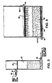
- FIG. 5 shows a cross section of one of the two identical hydrocarbon encapsulation tanks 10, 11.
- the liquid flow enters the primary hydrocarbon encapsulation tank 10 through the hydrocarbon encapsulation tank inlet 40 where it is met by a disbursal screen.
- This interior screening 42 serves as a filtrate retention and hold down as well as increasing the surface area of the incoming liquid entering the absorption section 43.
- the absorption section 43 is filled with the hydrocarbon bonding agent, hydrocarbon encapsulating polymer filtrate.
- the polymer combined with activated charcoal which facilitates flow through the filter bed, adsorbs, absorbs, encapsulates, and bonds any hydrocarbon that the filtrate comes in contact with.
- the flow rate of liquid, in gallons per minute is multiplied by five (5) minutes, the contact time required for proper bonding of hydrocarbons.
- Two hydrocarbon encapsulating tanks 10, 11 are used in this system to prevent a total shutdown of the system when the filtrate bed in the absorption section 43 of the primary tank has been exhausted. Exhaustion of the bed is not predictable due to the varying rates of hydrocarbon contamination; therefore, to avoid shutdown, the liquid flowing from the bag filter 8 is sent to the secondary hydrocarbon encapsulating tank 11 upon exhaustion of the filtrate bed in the primary tank 10.
- a pipe spool piece filled with a hydrocarbon encapsulating material that turns solid when in contact with hydrocarbons, will plug the discharge line 44 of the primary tank 10 when the encapsulating bed is expended. Since the flow rate has been stopped by the spool plug, the level in the first tank, the vertical plate separation tank 6, will rise until a safety float, not shown in the figures, shuts down the intake pump 2. When this occurs a piping bypass valve is opened which directs the liquid flow to the secondary tank 11.
- the secondary tank 11 also has a pipe spool safety piece to prevent any discharge of hydrocarbon contaminated liquid due to filtrate bed exhaustion.
- the bonding media used to encapsulate the hydrocarbons is not effective on heavy metal contaminants, the liquid will need to be exposed to the ceramic ion exchange heavy metal bonding filtrate media 48 contained in the heavy metal bonding tank 12.
- the liquid enters the heavy metal bonding tank 12 through the tank's inlet 45, where it is sprayed through a pipe 46 containing many small outlet holes.
- the sprayed liquid then travels through a disbursal screen, and mixes with the ceramic ion exchange heavy metal bonding filtrate media 48.
- the liquid must be in contact with the filtrate bed for ten (10) minutes; therefore, the flow rate in gallons per minute is multiplied by ten (10) to determine filtrate bed size 48 in gallons.
- the heavy metals bonding tank 12 will not need a backup tank as the life of the filtrate bed is significantly longer than that of the hydrocarbon encapsulating tanks 10, 11. Furthermore, it is possible to test the condition of the heavy metal encapsulating bed 48 with equipment supplied in the tool/spare part locker 14.
- the entire unit and all tanks are to be constructed out of 304 Stainless Steel.
- the good strength to weight ratio of this particular metal will also aid in portability.
- the inlet 61 of the filter receives liquid from any preceding filtering devices. Once the liquid passes through the polishing filter's housing canister, it is discharged into a natural water source through its drain 73. The treated water can be discharged into a natural water source since it now meets local, national and international laws on effluent from marine, commercial and industrial activities. This is so because the polishing filter media 69 (Fig. 8) effectively removes emulsified and dissolved oils and other hydrocarbons which are not removed by any other treatment facilities if they exist.
- an exploded internal view of the canister 65 is shown, depicting the sequence in which the water contacts each of he internal components.
- the water will first contact the polishing filter media 69.
- This media 69 is a bonding agent which encapsulates hydrocarbons which are present in the flow, including free, dissolved and emulsified oil.
- the bonding agent can be of any type that can perform this chemical encapsulation, such as agent A620, manufactured by the NO-CHAR company.
- the bonding process is accomplished by forcing contact between the targeted chemicals and the bonding agent.
- the level in the canister and the consequential time of contact can be adjusted by the level control pipe 67.
- the liquid is discharged through a vacuum break 72.
- the water Before being discharged, the water will also be strained through a size discriminating filter 70 which will remove any solids that may remain in the water as well as provide a housing for the polishing filter media 69.
- This filter 70 is supported by a rigid forming screen 71 to maintain a uniform layer of the filter 70 across a cross section of the canister 65.
- the encapsulation process will inevitably deplete the polishing filter media 69 and it will therefore need to be replenished by replacement.
- Replacement is accomplished by venting any pressure in the canister through the pressure vent valve 64, and then removing four equidistant quick release clamps 62 located at the top of the canister housing 65 and removing the canister lid 63. Once open, the polishing filter media 69 is lifted out of the canister 63 by its handle 68. A new bag of polishing filter media 69 is then placed into the size discriminating filter 70 and the lid 63 is replaced.
- the filter's size discriminating filter 70 which prevents any small solid contaminants from being discharged, will also require cleaning or replacement when it becomes clogged from prolonged use.
- the process by which the filter 70 will be exchanged with a new one will be identical to that of replacing the polishing filter media bag 69, except that an additional step of removing the polishing filter bag 69, in order to get to the filter 70, is required.
- polishing filter media 69 or of the size discriminating filter 70 only the polishing filter canister 65 will need to be drained through the drain and sample tube 66 and not the entire system. Therefore, replacement will be completed without shutdown of the entire decontamination process.
Landscapes
- Chemical & Material Sciences (AREA)
- Chemical Kinetics & Catalysis (AREA)
- Physics & Mathematics (AREA)
- Thermal Sciences (AREA)
- Health & Medical Sciences (AREA)
- Clinical Laboratory Science (AREA)
- Life Sciences & Earth Sciences (AREA)
- Hydrology & Water Resources (AREA)
- Engineering & Computer Science (AREA)
- Environmental & Geological Engineering (AREA)
- Water Supply & Treatment (AREA)
- Organic Chemistry (AREA)
- Filtration Of Liquid (AREA)
- Removal Of Specific Substances (AREA)
- Water Treatment By Sorption (AREA)
- Separation Using Semi-Permeable Membranes (AREA)
Applications Claiming Priority (4)
| Application Number | Priority Date | Filing Date | Title |
|---|---|---|---|
| US08/429,684 US5626748A (en) | 1995-04-27 | 1995-04-27 | Liquid separator |
| US429684 | 1995-04-27 | ||
| US506817 | 1995-07-25 | ||
| US08/506,817 US5626746A (en) | 1995-07-25 | 1995-07-25 | Filtering device containing chemical encapsulation filter and size discriminating filter |
Publications (2)
| Publication Number | Publication Date |
|---|---|
| EP0739858A2 true EP0739858A2 (de) | 1996-10-30 |
| EP0739858A3 EP0739858A3 (de) | 1997-09-17 |
Family
ID=27028296
Family Applications (1)
| Application Number | Title | Priority Date | Filing Date |
|---|---|---|---|
| EP96201160A Withdrawn EP0739858A3 (de) | 1995-04-27 | 1996-04-29 | Flüssigkeitsabscheider und Filter dafür |
Country Status (6)
| Country | Link |
|---|---|
| EP (1) | EP0739858A3 (de) |
| JP (1) | JPH09117798A (de) |
| CN (1) | CN1139585A (de) |
| AU (1) | AU5194096A (de) |
| CA (1) | CA2175265A1 (de) |
| NO (1) | NO961736L (de) |
Cited By (8)
| Publication number | Priority date | Publication date | Assignee | Title |
|---|---|---|---|---|
| ES2164617A1 (es) * | 2000-09-22 | 2002-02-16 | Cabre Javier Martin | Equipo separador de aguas hidrocarburadas. |
| US7470361B2 (en) | 2003-11-14 | 2008-12-30 | Eberly Christopher N | System for stormwater environmental control |
| WO2011095755A1 (en) * | 2010-02-03 | 2011-08-11 | H2Ology Limited | Waste water recovery |
| EP2160361A4 (de) * | 2007-06-27 | 2011-08-24 | Harry Granlund | Verfahren zur entfernung von stickstoff und phosphor aus grauwasser und entsprechende vorrichtung |
| WO2014085750A1 (en) * | 2012-11-28 | 2014-06-05 | Early Daniel M | Rapid deployable packaged wastewater treatment system |
| IT201900013410A1 (it) * | 2019-07-31 | 2021-01-31 | Pragma Blue S R L | Impianto mobile perfezionato per il trattamento di acque reflue derivate dal lavaggio di pavimenti |
| CN113262525A (zh) * | 2021-05-20 | 2021-08-17 | 大连理工大学 | 一种连续水油分离装置 |
| WO2025059053A1 (en) * | 2023-09-12 | 2025-03-20 | Saudi Arabian Oil Company | Water oil separator vessel with hydrophobic mesh tubes |
Families Citing this family (5)
| Publication number | Priority date | Publication date | Assignee | Title |
|---|---|---|---|---|
| JP2002126720A (ja) * | 2000-10-18 | 2002-05-08 | Japan Organo Co Ltd | 水処理装置における塔装置の組立方法および構造 |
| US7998250B2 (en) * | 2008-10-03 | 2011-08-16 | B/E Aerospace, Inc. | Multiple vortex waste separator apparatus |
| CN102389665B (zh) * | 2011-07-29 | 2014-04-30 | 中国科学院成都生物研究所 | 一种模块化过滤装置及其使用方法和用途 |
| AU2018371752B2 (en) * | 2017-11-21 | 2023-12-14 | Thermaco Incorporated | Solids transfer pump with modular components |
| CN110627447A (zh) * | 2019-10-22 | 2019-12-31 | 深圳市信泰工业自动化设备有限公司 | 一种透水混凝土污水过滤装置及其方法 |
Family Cites Families (7)
| Publication number | Priority date | Publication date | Assignee | Title |
|---|---|---|---|---|
| CA1090262A (en) * | 1977-02-14 | 1980-11-25 | William M. Lynch | Vertical tube liquid pollutant separator |
| JPS607937A (ja) * | 1983-06-24 | 1985-01-16 | Mitsui Mining Co Ltd | 重金属吸着剤の製造方法 |
| CH678523A5 (de) * | 1989-07-17 | 1991-09-30 | Awatec Ag | |
| US5120435A (en) * | 1991-01-30 | 1992-06-09 | Fink Ronald G | Pre-treatment sewer discharge system |
| DE9202643U1 (de) * | 1992-02-28 | 1992-04-09 | Ultrafilter GmbH, 5657 Haan | Trennvorrichtung für Öl/Wasser-Gemische |
| JPH0680955A (ja) * | 1992-09-02 | 1994-03-22 | Nippon Shokubai Co Ltd | 粒状吸油剤の製造方法 |
| DE4416130C2 (de) * | 1994-05-06 | 1996-06-13 | Suedleder Gmbh & Co | Verfahren zur Behandlung schwermetallhaltiger Abwässer aus der Lederherstellung und ähnlich beschaffener Abwässer |
-
1996
- 1996-04-29 NO NO961736A patent/NO961736L/no unknown
- 1996-04-29 CA CA002175265A patent/CA2175265A1/en not_active Abandoned
- 1996-04-29 AU AU51940/96A patent/AU5194096A/en not_active Abandoned
- 1996-04-29 CN CN96103853A patent/CN1139585A/zh active Pending
- 1996-04-29 EP EP96201160A patent/EP0739858A3/de not_active Withdrawn
- 1996-04-30 JP JP8144801A patent/JPH09117798A/ja active Pending
Cited By (10)
| Publication number | Priority date | Publication date | Assignee | Title |
|---|---|---|---|---|
| ES2164617A1 (es) * | 2000-09-22 | 2002-02-16 | Cabre Javier Martin | Equipo separador de aguas hidrocarburadas. |
| US7470361B2 (en) | 2003-11-14 | 2008-12-30 | Eberly Christopher N | System for stormwater environmental control |
| US7780855B2 (en) | 2003-11-14 | 2010-08-24 | Eberly Christopher N | Method for pre-engineering a system for environmental control of storm water |
| EP2160361A4 (de) * | 2007-06-27 | 2011-08-24 | Harry Granlund | Verfahren zur entfernung von stickstoff und phosphor aus grauwasser und entsprechende vorrichtung |
| WO2011095755A1 (en) * | 2010-02-03 | 2011-08-11 | H2Ology Limited | Waste water recovery |
| WO2014085750A1 (en) * | 2012-11-28 | 2014-06-05 | Early Daniel M | Rapid deployable packaged wastewater treatment system |
| IT201900013410A1 (it) * | 2019-07-31 | 2021-01-31 | Pragma Blue S R L | Impianto mobile perfezionato per il trattamento di acque reflue derivate dal lavaggio di pavimenti |
| CN113262525A (zh) * | 2021-05-20 | 2021-08-17 | 大连理工大学 | 一种连续水油分离装置 |
| CN113262525B (zh) * | 2021-05-20 | 2022-04-08 | 大连理工大学 | 一种连续水油分离装置 |
| WO2025059053A1 (en) * | 2023-09-12 | 2025-03-20 | Saudi Arabian Oil Company | Water oil separator vessel with hydrophobic mesh tubes |
Also Published As
| Publication number | Publication date |
|---|---|
| EP0739858A3 (de) | 1997-09-17 |
| CA2175265A1 (en) | 1996-10-28 |
| JPH09117798A (ja) | 1997-05-06 |
| AU5194096A (en) | 1996-11-07 |
| CN1139585A (zh) | 1997-01-08 |
| NO961736D0 (no) | 1996-04-29 |
| NO961736L (no) | 1996-10-28 |
Similar Documents
| Publication | Publication Date | Title |
|---|---|---|
| US5626748A (en) | Liquid separator | |
| US7597803B2 (en) | Multi-phase separation system | |
| US6616834B2 (en) | Wastewater processor | |
| US5637234A (en) | Apparatus and method for separating fluids having different specific gravities, such as oil and water | |
| US7578930B2 (en) | Mobile water treatment system | |
| JP3640070B2 (ja) | 油水分離除去装置 | |
| KR101096538B1 (ko) | 선박용 유수 자동 분리 및 회수 시스템 | |
| CA2175265A1 (en) | Liquid separator and polishing filter therefor | |
| US20220162093A1 (en) | Ballast water, bilge water, slop water, or oily water treatment systems and related methods | |
| US4116835A (en) | Pollution control system | |
| JP4151005B2 (ja) | 油水分離装置並びに油水分離方法 | |
| US6616835B2 (en) | Coolant recycling system | |
| US6129839A (en) | Separation system for immiscible liquids | |
| KR100542338B1 (ko) | 눈금판 필터 모듈이 구비된 유수분리장치 | |
| JPH0550060A (ja) | 含油水処理装置 | |
| US5626746A (en) | Filtering device containing chemical encapsulation filter and size discriminating filter | |
| JP2767768B2 (ja) | 油水分離装置 | |
| KR200330431Y1 (ko) | 유수 분리기 | |
| KR20050058765A (ko) | 오존접촉식 가압부상 오폐수처리시스템 및 오폐수처리방법 | |
| CA2614231A1 (en) | Fluid treatment method and apparatus | |
| US6652750B1 (en) | Externally mounted bilge water filter and methods therefor | |
| US6726837B2 (en) | Portable bilge water filter apparatus | |
| JP2931549B2 (ja) | 燃料タンク洗浄排水処理方法及び装置 | |
| GB2189161A (en) | Separators | |
| US20060260658A1 (en) | Closed-loop containment assembly and method for a pressure washing apparatus with a non-recirculating fluid heating compartment |
Legal Events
| Date | Code | Title | Description |
|---|---|---|---|
| PUAI | Public reference made under article 153(3) epc to a published international application that has entered the european phase |
Free format text: ORIGINAL CODE: 0009012 |
|
| AK | Designated contracting states |
Kind code of ref document: A2 Designated state(s): DE FR GB GR IT |
|
| PUAL | Search report despatched |
Free format text: ORIGINAL CODE: 0009013 |
|
| AK | Designated contracting states |
Kind code of ref document: A3 Designated state(s): DE FR GB GR IT |
|
| STAA | Information on the status of an ep patent application or granted ep patent |
Free format text: STATUS: THE APPLICATION IS DEEMED TO BE WITHDRAWN |
|
| 18D | Application deemed to be withdrawn |
Effective date: 19980318 |