EP0741221A1 - Anordnung zum Identifizieren der Richtung eines Senders - Google Patents
Anordnung zum Identifizieren der Richtung eines Senders Download PDFInfo
- Publication number
- EP0741221A1 EP0741221A1 EP96303058A EP96303058A EP0741221A1 EP 0741221 A1 EP0741221 A1 EP 0741221A1 EP 96303058 A EP96303058 A EP 96303058A EP 96303058 A EP96303058 A EP 96303058A EP 0741221 A1 EP0741221 A1 EP 0741221A1
- Authority
- EP
- European Patent Office
- Prior art keywords
- transmitter
- signal
- receiver
- comparator
- antennas
- Prior art date
- Legal status (The legal status is an assumption and is not a legal conclusion. Google has not performed a legal analysis and makes no representation as to the accuracy of the status listed.)
- Granted
Links
Images



Classifications
-
- G—PHYSICS
- G07—CHECKING-DEVICES
- G07C—TIME OR ATTENDANCE REGISTERS; REGISTERING OR INDICATING THE WORKING OF MACHINES; GENERATING RANDOM NUMBERS; VOTING OR LOTTERY APPARATUS; ARRANGEMENTS, SYSTEMS OR APPARATUS FOR CHECKING NOT PROVIDED FOR ELSEWHERE
- G07C9/00—Individual registration on entry or exit
- G07C9/00174—Electronically operated locks; Circuits therefor; Nonmechanical keys therefor, e.g. passive or active electrical keys or other data carriers without mechanical keys
- G07C9/00182—Electronically operated locks; Circuits therefor; Nonmechanical keys therefor, e.g. passive or active electrical keys or other data carriers without mechanical keys operated with unidirectional data transmission between data carrier and locks
-
- G—PHYSICS
- G01—MEASURING; TESTING
- G01S—RADIO DIRECTION-FINDING; RADIO NAVIGATION; DETERMINING DISTANCE OR VELOCITY BY USE OF RADIO WAVES; LOCATING OR PRESENCE-DETECTING BY USE OF THE REFLECTION OR RERADIATION OF RADIO WAVES; ANALOGOUS ARRANGEMENTS USING OTHER WAVES
- G01S3/00—Direction-finders for determining the direction from which infrasonic, sonic, ultrasonic or electromagnetic waves, or particle emission, not having a directional significance, are being received
- G01S3/02—Direction-finders for determining the direction from which infrasonic, sonic, ultrasonic or electromagnetic waves, or particle emission, not having a directional significance, are being received using radio waves
- G01S3/14—Systems for determining direction or deviation from predetermined direction
- G01S3/28—Systems for determining direction or deviation from predetermined direction using amplitude comparison of signals derived simultaneously from receiving antennas or antenna systems having differently-oriented directivity characteristics
-
- G—PHYSICS
- G07—CHECKING-DEVICES
- G07C—TIME OR ATTENDANCE REGISTERS; REGISTERING OR INDICATING THE WORKING OF MACHINES; GENERATING RANDOM NUMBERS; VOTING OR LOTTERY APPARATUS; ARRANGEMENTS, SYSTEMS OR APPARATUS FOR CHECKING NOT PROVIDED FOR ELSEWHERE
- G07C9/00—Individual registration on entry or exit
- G07C9/00174—Electronically operated locks; Circuits therefor; Nonmechanical keys therefor, e.g. passive or active electrical keys or other data carriers without mechanical keys
- G07C9/00182—Electronically operated locks; Circuits therefor; Nonmechanical keys therefor, e.g. passive or active electrical keys or other data carriers without mechanical keys operated with unidirectional data transmission between data carrier and locks
- G07C2009/00206—Electronically operated locks; Circuits therefor; Nonmechanical keys therefor, e.g. passive or active electrical keys or other data carriers without mechanical keys operated with unidirectional data transmission between data carrier and locks the keyless data carrier being hand operated
- G07C2009/00214—Electronically operated locks; Circuits therefor; Nonmechanical keys therefor, e.g. passive or active electrical keys or other data carriers without mechanical keys operated with unidirectional data transmission between data carrier and locks the keyless data carrier being hand operated by one push button
-
- G—PHYSICS
- G07—CHECKING-DEVICES
- G07C—TIME OR ATTENDANCE REGISTERS; REGISTERING OR INDICATING THE WORKING OF MACHINES; GENERATING RANDOM NUMBERS; VOTING OR LOTTERY APPARATUS; ARRANGEMENTS, SYSTEMS OR APPARATUS FOR CHECKING NOT PROVIDED FOR ELSEWHERE
- G07C9/00—Individual registration on entry or exit
- G07C9/00174—Electronically operated locks; Circuits therefor; Nonmechanical keys therefor, e.g. passive or active electrical keys or other data carriers without mechanical keys
- G07C9/00182—Electronically operated locks; Circuits therefor; Nonmechanical keys therefor, e.g. passive or active electrical keys or other data carriers without mechanical keys operated with unidirectional data transmission between data carrier and locks
- G07C2009/00261—Electronically operated locks; Circuits therefor; Nonmechanical keys therefor, e.g. passive or active electrical keys or other data carriers without mechanical keys operated with unidirectional data transmission between data carrier and locks the keyless data carrier having more than one function
-
- G—PHYSICS
- G07—CHECKING-DEVICES
- G07C—TIME OR ATTENDANCE REGISTERS; REGISTERING OR INDICATING THE WORKING OF MACHINES; GENERATING RANDOM NUMBERS; VOTING OR LOTTERY APPARATUS; ARRANGEMENTS, SYSTEMS OR APPARATUS FOR CHECKING NOT PROVIDED FOR ELSEWHERE
- G07C9/00—Individual registration on entry or exit
- G07C9/00174—Electronically operated locks; Circuits therefor; Nonmechanical keys therefor, e.g. passive or active electrical keys or other data carriers without mechanical keys
- G07C2009/00753—Electronically operated locks; Circuits therefor; Nonmechanical keys therefor, e.g. passive or active electrical keys or other data carriers without mechanical keys operated by active electrical keys
- G07C2009/00769—Electronically operated locks; Circuits therefor; Nonmechanical keys therefor, e.g. passive or active electrical keys or other data carriers without mechanical keys operated by active electrical keys with data transmission performed by wireless means
- G07C2009/00793—Electronically operated locks; Circuits therefor; Nonmechanical keys therefor, e.g. passive or active electrical keys or other data carriers without mechanical keys operated by active electrical keys with data transmission performed by wireless means by Hertzian waves
-
- G—PHYSICS
- G07—CHECKING-DEVICES
- G07C—TIME OR ATTENDANCE REGISTERS; REGISTERING OR INDICATING THE WORKING OF MACHINES; GENERATING RANDOM NUMBERS; VOTING OR LOTTERY APPARATUS; ARRANGEMENTS, SYSTEMS OR APPARATUS FOR CHECKING NOT PROVIDED FOR ELSEWHERE
- G07C2209/00—Indexing scheme relating to groups G07C9/00 - G07C9/38
- G07C2209/60—Indexing scheme relating to groups G07C9/00174 - G07C9/00944
- G07C2209/63—Comprising locating means for detecting the position of the data carrier, i.e. within the vehicle or within a certain distance from the vehicle
Definitions
- the present invention relates to transmitter direction identifiers and, more particularly, to transmitter direction identifiers capable of creating command signals depending on the direction identified.
- Transmitter direction identifiers are complicated in design and construction. Complex designs often increase the size of both the transmitter and the receiver to a burdensome weight inhibiting the portability thereof. In environments where mobility is required, i.e., the automotive environment, these systems are not used. Therefore, it is desired to implement a low cost, low complexity transmitter direction identifier capable of being manually portable.
- the present invention is a transmitter direction identifier.
- the present invention includes a transmitter for sending a coded signal.
- a receiver receives the coded signal from the transmitter and a spatial differentiator locates the transmitter relative to the receiver from the coded signal received from the transmitter.
- the spatial differentiator creates a location signal.
- a control unit is electrically connected to the spatial differentiator and converts the location signal into a command signal for subsequent use.
- the advantages associated with the present invention include providing a low cost, reliable, durable transmitter direction identifier capable of being used in hostile automotive environments.
- a transmitter direction identifying assembly is generally indicated at 10.
- the transmitter direction identifying assembly 10 is shown in conjunction with automotive keyless entry assembly 11.
- the transmitter direction identifying assembly 10 and the automotive keyless entry assembly 11 include automatic trunk and light systems, will be discussed together as an example of one embodiment of the present invention. A non-exhaustive list of other embodiments include home entry systems, lighting systems for any type of enclosure and the like.
- the present invention 10 provides access to an occupant compartment 12 of an automotive vehicle 14 by unlocking at least one of a plurality of doors 16.
- the automotive keyless entry assembly 11 uses the transmitter direction identifier 10 to unlock the doors on one side of the automotive vehicle 14 at a time. More specifically, the automotive keyless entry assembly 11 unlocks one or two doors of a two door automotive vehicle or a four door automotive vehicle, respectively.
- a transmitter 18 sends a coded signal to a receiver 20 located within the automotive vehicle 14. Transmission consists of a wake up pulse, eight synchronisation pulses and a number of identification pulses or bits to allow for a reasonable number of unique identification codes, e.g., 32 bits.
- the transmitter 18 is a key grip in one embodiment. In other embodiments, the transmitter 18 may be a key fob or a credit card sized device which can be stored in the wallet of the operator. The size and appearance of the transmitter 18 is not a part of the present invention.
- the receiver 20 receives the coded signal from the transmitter 18.
- the receiver 20 includes a low noise amplifier 22 which amplifies the coded signal and transmits the amplified signal to a super regenerative oscillator 24.
- the super regenerative oscillator 24 is gated by a quench oscillator 26 and provides a means for further amplifying and detecting the coded signal.
- the super regenerative oscillator 24 is operating at 315 Mhz whereas the quench oscillator is operating at approximately 1 Mhz.
- a base band amplifier 28 receives the amplified coded signal after it passes through the oscillators 24,26 for further amplification.
- the receiver 20 is a UHF receiver in one embodiment.
- a spatial differentiator 30 locates a transmitter 18 relative to the automotive vehicle 14.
- the spatial differentiator 30 locates the transmitter 18 from the coded signal received from the receiver 20.
- the spatial differentiator 30 creates a location signal from the coded signal. The spatial differentiator 30 will be further discussed subsequently.
- the transmitter direction identifying assembly 10 in this embodiment further includes a control unit 32 which is electrically connected to the spatial differentiator 30.
- the control unit 32 converts the location signal into an unlock signal to unlock the locking mechanism 34 associated with one of the plurality of doors 16 closest to the transmitter 18.
- the control unit 32 would send an unlock signal to two of the unlocking mechanisms associated with the two doors 16 which are on the same side of the automotive vehicle 14 as the transmitter 18. If the receiver 20 is unable to determine which side the transmitter 18 is on with respect to the automotive vehicle 14, the control unit 32 will unlock the locks 34 associated with the doors 16 adjacent the driver seat as a default parameter.
- the spatial differentiator is shown to include a base band filter 36.
- the cut-off frequency, f c is approximately 50 kHz.
- the high comparator 38 defines a high threshold 42 whereas the low comparator 40 defines a low threshold 44.
- the comparators 38,40 compare the coded signal received thereby against the high threshold 42 and low threshold 44, respectively, and creates a digital output 47, 48 representing the portion of the signal which exceeds the high threshold 42 and low threshold 44.
- the transmitter direction identifying assembly 10 includes a first antenna 46 and a second antenna 48.
- the first antenna 46 and second antenna 48 are operatively connected to the receiver 20.
- Each of the first antenna 46 and second antenna 48 receive the coded signal from the transmitter 18.
- the antennas 46,48 are directional.
- the antennas 46,48 are spaced apart and located in the rear quarter panels of the automotive vehicle 14. Although not necessary, the antennas 46,48 are spaced such that their signal receiving areas overlap slightly.
- An antenna multiplexor 50 is electrically connected between both the first antenna 46 and the second antenna 48 and the receiver 20 to alternately transmit the first and second antenna signals to the receiver 20.
- the antenna multiplexor 50 switches between the two antennas 46,48 and is controlled by the control unit 32.
- the antenna multiplexor 50 allows each of the two antennas 46,48 to transmit the antenna signals received therefrom to the receiver 20 for equal amounts of time.
- the control unit 32 includes a correlator 54 which correlates the high pulse width signal with the low pulse width signal of their respective antenna signals.
- a correlator 54 which correlates the high pulse width signal with the low pulse width signal of their respective antenna signals.
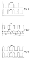
- FIGs. 6 and 8 two representations of possible correlations are shown for the passenger side antenna 48. If, for example, the transmitter 18 is on the passenger side of the automotive vehicle 14, a high pulse width correlation between the high comparator signal and low comparator signal would occur, shown in FIG. 8. Likewise, in the same example, the driver side antenna, or first antenna 46, would have a low pulse width correlation between the low comparator signal and the high pulse width signal, as depicted in FIG. 6. More specifically, the correlator 54 correlates the pulse width of the signals which are created by comparing the antenna signals with the high and low thresholds.
- the passenger side or second antenna 48 receives a relatively strong signal allowing large pulse widths for both the high pulse width and low pulse width signal.
- the driver side or first antenna 46 produces, however, a slightly weaker signal because the transmitter 18 is further from the driver side antenna 46. Therefore, the weaker signal cannot produce such a large pulse width for the high pulse width signal and, therefore, the pulse widths are substantially unequal to each other.
- the control unit 32 can then determine that because the pulse widths of the passenger side antenna 48 have a high correlation, the transmitter 18 must be located to the passenger side of the automotive vehicle 14.
- the control unit 32 further includes a decoder 56 which decodes the decoded signal from the transmitter 18.
- the control unit 32 determines the coded signal matches the signal the control unit is programmed to receive and unlocks the specific locks 34. If the coded signal is not decoded to match what should be received, the locks 34 will remain locked preventing access to the occupant compartment 12 through any of the doors 16.
- the control unit 32 which includes the correlator 54 and decoder 56, is a microprocessor 58, shown in FIG. 3.
- the microprocessor 58 may be any commercially available product.
- the schematic of the spatial differentiator 30 is shown.
- the signal, as it passes through the receiver 20 and received by the spatial generator 30 is represented by the signal generator 60.
- the signal is coupled to the spatial differentiator 30 through a capacitor 62.
- the capacitor 62 is connected to the inverting input of an operational amplifier (op amp) 70 through a first resistor 72.
- the non-inverting input of the op amp 70 is connected to the power source 66 through a second resistor 74.
- the non-inverting input of the op amp 70 is also connected to ground through a third resistor 76.
- a feedback loop is created by connecting the output of the op amp 70 to the inverting input of the op amp 70 through a fourth resistor 78.
- the output of the op amp 70 is also connected to the inverting inputs of both the high comparator 38 and the low comparator 40.
- a first voltage divider 79 is created by a fifth resistor 80 and sixth resistor 82. Seventh and eighth resistors 84,86 create a second voltage divider 88. The sixth resistor 82 and the eighth resistor 86 have different values such that the voltage is divided differently between the two voltage dividers 79,88. The differing voltage divisions create the high threshold 42 and low threshold 44. Both of the voltage dividers 78,88 extend between the power source 66 and ground.
- the non-inverting input of the high comparator 38 is connected between the fifth and sixth resistors 80,82 of the first voltage divider 79.
- the non-inverting input of the low comparator 40 is connected between the seventh and eighth resistors 84,86 of the second voltage divider 88.
- the outputs of the high comparator 38 and the low comparator 40 are connected to the microprocessor 58 for processing by the control unit 32.
- Ninth resistor 90 and tenth resistor 92 are connected between the output of the high comparator 38 and the low comparator 40, respectively, and ground.
- the op amp 70 and, the high comparator 38, and the low comparator 40 are all powered by the power source 66 and grounded to a common ground.
- the microprocessor 58 chooses the first antenna as represented by block 94 in FIG. 9.
- the microprocessor 58 chooses the first antenna by switching the antenna multiplexor 50.
- the receiver 20 receives four pulses from the signal received from the first antenna 46.
- the spatial differentiator 30 receives the signal, creates two signals corresponding to the high threshold 42, and low threshold 44, and sends the two signals to the microprocessor 58.
- the microprocessor 58 determines as represented by block 96, the correlation coefficient for the first antenna 46. The coefficient is stored in the microprocessor 58 for future use.
- the microprocessor 58 then chooses the second antenna 48, using the antenna multiplexor 50 and, similarly, receives four pulses of the signal and determines the correlation coefficient therefor.
- the antenna with the highest correlation coefficient is then selected. In one embodiment, if the correlation coefficient exceeds 0.7, the antenna associated with that correlation coefficient is selected. More specifically, a selection is made to use the antenna with the highest correlation coefficient when the correlation coefficient exceeds 0.7, indicating a transmitter 18 is in close proximity to the receiver 20 and, hence, the automotive vehicle 14. The remaining pulses of the signal are then decoded and depending if the signal received matches the unlock code stored in the microprocessor 58, the doors 16 associated with the chosen antenna are unlocked. It can be appreciated by those skilled in the art that four antennas may be used instead of two antennas 46,48 to further delineate the location of the transmitter 18 to unlock a single door in a four door automotive vehicle.
Landscapes
- Engineering & Computer Science (AREA)
- Physics & Mathematics (AREA)
- General Physics & Mathematics (AREA)
- Computer Networks & Wireless Communication (AREA)
- Radar, Positioning & Navigation (AREA)
- Remote Sensing (AREA)
- Lock And Its Accessories (AREA)
- Radio Transmission System (AREA)
Applications Claiming Priority (2)
| Application Number | Priority Date | Filing Date | Title |
|---|---|---|---|
| US08/433,184 US5710548A (en) | 1995-05-03 | 1995-05-03 | Transmitter direction identifier |
| US433184 | 1995-05-03 |
Publications (2)
| Publication Number | Publication Date |
|---|---|
| EP0741221A1 true EP0741221A1 (de) | 1996-11-06 |
| EP0741221B1 EP0741221B1 (de) | 2002-06-12 |
Family
ID=23719153
Family Applications (1)
| Application Number | Title | Priority Date | Filing Date |
|---|---|---|---|
| EP96303058A Expired - Lifetime EP0741221B1 (de) | 1995-05-03 | 1996-05-01 | Anordnung zum Identifizieren der Richtung eines Senders |
Country Status (4)
| Country | Link |
|---|---|
| US (1) | US5710548A (de) |
| EP (1) | EP0741221B1 (de) |
| JP (1) | JPH08312213A (de) |
| DE (1) | DE69621700T2 (de) |
Cited By (6)
| Publication number | Priority date | Publication date | Assignee | Title |
|---|---|---|---|---|
| DE19820921A1 (de) * | 1998-05-09 | 1999-11-11 | Bayerische Motoren Werke Ag | Mobiler Transponder für ein Fahrzeug |
| WO2000027675A1 (de) * | 1998-11-05 | 2000-05-18 | Trw Automotive Electronics & Components Gmbh & Co. Kg | Sende- und/oder empfangseinrichtung, insbesondere für ein kfz |
| EP1013860A1 (de) * | 1998-12-11 | 2000-06-28 | Mannesmann VDO Aktiengesellschaft | Schliesseinrichtung für ein mehrere Türen aufweisendes Kraftfahrzeug |
| DE19938951A1 (de) * | 1999-08-17 | 2001-03-01 | Deutsche Telekom Ag | Vorrichtung und Verfahren zum Auffinden eines mobilen Objekts |
| EP1081316A1 (de) * | 1999-08-31 | 2001-03-07 | Mannesmann VDO Aktiengesellschaft | Positionserkennung für Funkschlüssel |
| EP1283503A3 (de) * | 2001-08-10 | 2004-05-26 | ArvinMeritor Light Vehicle Systems (UK) Ltd | Zugangskontrollsystem und -verfahren |
Families Citing this family (27)
| Publication number | Priority date | Publication date | Assignee | Title |
|---|---|---|---|---|
| JP3292025B2 (ja) * | 1996-02-27 | 2002-06-17 | 日産自動車株式会社 | 車両用キーレスシステムの自動ロック装置 |
| DE19827586B4 (de) * | 1998-06-20 | 2007-09-20 | Leopold Kostal Gmbh & Co. Kg | Schlüssellose Zugangskontrolleinrichtung für Kraftfahrzeuge sowie Verfahren zum Durchführen einer schlüssellosen Zugangsberechtigungskontrolle bei Kraftfahrzeugen |
| DE19923409B4 (de) * | 1999-05-21 | 2004-10-07 | Siemens Ag | Verfahren und Vorrichtung zur Ortsbestimmung eines Senders im Raum |
| DE19938898C1 (de) * | 1999-08-17 | 2001-04-05 | Siemens Ag | Einrichtung zur Berechtigungsidentifizierung und Auslösung/Freigabe einer Aktion, insbesondere elektronische Schließeinrichtung für Kraftfahrzeuge, und Basiseinheit und Schlüsseleinheit zur Realisierung einer derartigen Einrichtung |
| JP4552169B2 (ja) | 1999-11-09 | 2010-09-29 | マツダ株式会社 | 車両の開閉体制御装置 |
| US6380643B1 (en) * | 1999-11-18 | 2002-04-30 | Siemens Automotive Corporation | Integrated antenna for use with passive entry and ignition system |
| FR2809250B1 (fr) * | 2000-05-19 | 2003-10-03 | Sagem | Recepteur radio courte portee, a antenne a lobe orientable, de donnees de vehicule automobile |
| US6396412B1 (en) * | 2000-08-23 | 2002-05-28 | Siemens Automotive Corporation | Passive RF-RF entry system for vehicles |
| US7911324B2 (en) * | 2001-02-16 | 2011-03-22 | Automotive Technologies International, Inc. | Method and system for obtaining information about RFID-equipped objects |
| US6724322B2 (en) | 2001-12-21 | 2004-04-20 | Lear Corporation | Remote system for providing vehicle information to a user |
| US6906612B2 (en) * | 2002-04-11 | 2005-06-14 | Lear Corporation | System and method for vehicle passive entry having inside/outside detection |
| US6864781B1 (en) | 2002-04-12 | 2005-03-08 | Thomas O. Loomis | Portable paging system |
| FR2847610B1 (fr) * | 2002-11-22 | 2005-01-07 | Siemens Vdo Automotive | Procede de condamnation automatique d'un vehicule a l'eloignement |
| DE102004036258B4 (de) * | 2004-07-26 | 2008-01-03 | Siemens Ag | Verfahren und Vorrichtung zur Lokalisierung einer als ID-Geber, insbesondere Fahrzeugschlüssel, ausgebildeten mobilen Sendeeinrichtung |
| JP2006124948A (ja) * | 2004-10-26 | 2006-05-18 | Alps Electric Co Ltd | 遠隔操作システム |
| DE102004059179B4 (de) * | 2004-12-08 | 2006-12-28 | Siemens Ag | Verfahren zur Lokalisierung einer Sende- und Empfangseinrichtung |
| DE102005032379A1 (de) * | 2005-07-08 | 2007-01-11 | Conti Temic Microelectronic Gmbh | Zugangskontrollsystem für ein Kraftfahrzeug |
| JP2007331712A (ja) * | 2006-06-19 | 2007-12-27 | Denso Corp | 車両制御システム |
| JP4887928B2 (ja) * | 2006-06-21 | 2012-02-29 | 株式会社デンソー | 車両用通信システムの受信装置 |
| JP4561848B2 (ja) * | 2008-03-06 | 2010-10-13 | 株式会社デンソー | 車両ドア制御システム |
| US8723729B2 (en) * | 2009-05-26 | 2014-05-13 | Broadcom Corporation | Angle of arrival and/or range estimation within a wireless communication device |
| US8744482B2 (en) * | 2011-03-25 | 2014-06-03 | Lear Corporation | Apparatus and method for wireless device detection |
| KR101406988B1 (ko) * | 2013-10-01 | 2014-07-18 | 콘티넨탈 오토모티브 시스템 주식회사 | 카드형 스마트키 장치 및 그 제어방법 |
| US9802574B2 (en) * | 2014-09-16 | 2017-10-31 | Qualcomm Incorporated | Relay attack inhibiting |
| DE102014220260A1 (de) | 2014-10-07 | 2016-04-07 | Continental Automotive Gmbh | Antennen-Multiplexer, Treiberschaltung mit einem Schaltelement und aktive Sendeeinrichtung mit einem Schaltelement |
| US11192523B2 (en) | 2017-02-22 | 2021-12-07 | Ford Global Technologies, Llc | Automatic power door opening on sustained presence |
| US11447099B2 (en) * | 2019-08-30 | 2022-09-20 | Denso International America, Inc. | Multiplexed antenna circuit network for ultra-high frequency low energy based phone as a key access to a vehicle |
Citations (4)
| Publication number | Priority date | Publication date | Assignee | Title |
|---|---|---|---|---|
| US4114157A (en) * | 1976-03-04 | 1978-09-12 | Toyo Ysushinki Kabushiki Kaisha | Bearing detection system |
| US5056106A (en) * | 1990-08-02 | 1991-10-08 | Wang James J | Golf course ranging and direction-finding system using spread-spectrum radiolocation techniques |
| EP0523602A1 (de) * | 1991-07-17 | 1993-01-20 | Bayerische Motoren Werke Aktiengesellschaft | Verfahren zum Erkennen eines im Fahrzeuginnern eingeschlossenen tragbaren Transponders |
| EP0596805A1 (de) * | 1992-11-06 | 1994-05-11 | Valeo Electronique | Fernbetätigungssystem zum Sperren und Entsperren von Türen und Öffnungsteilen eines Kraftfahrzeugs |
Family Cites Families (17)
| Publication number | Priority date | Publication date | Assignee | Title |
|---|---|---|---|---|
| US2915751A (en) * | 1959-12-01 | Intermediate | ||
| US2490777A (en) * | 1945-05-22 | 1949-12-13 | Herwil M Bryant | Indicator system |
| US2841787A (en) * | 1952-05-08 | 1958-07-01 | Ultra Electric Inc | Radio locating apparatus |
| US2979718A (en) * | 1957-11-19 | 1961-04-11 | Westinghouse Electric Corp | Automatic target tracking passive radar apparatus |
| US3824595A (en) * | 1971-06-04 | 1974-07-16 | Bunker Ramo | High accuracy direction finding system |
| CH565376A5 (de) * | 1972-08-15 | 1975-08-15 | Haas Paul | |
| US3906505A (en) * | 1973-10-09 | 1975-09-16 | Gen Instrument Corp | Method and apparatus for determining the direction of arrival of a signal |
| US4023176A (en) * | 1975-04-02 | 1977-05-10 | Texas Instruments Incorporated | Beacon tracking display system |
| GB2095497B (en) * | 1981-03-24 | 1984-08-15 | Racal Communications Equip | Improvements in and relating to direction finding |
| JPS6064537A (ja) * | 1983-09-19 | 1985-04-13 | Nissan Motor Co Ltd | 誘導電磁界を媒体とする車両用無線伝送装置 |
| US4868915A (en) * | 1984-02-23 | 1989-09-19 | Allied Corporation | Keyless entry system having remote marker for motor vehicles |
| JPS6237479A (ja) * | 1985-08-12 | 1987-02-18 | 日産自動車株式会社 | 無線式施解錠制御装置 |
| JPS6278379A (ja) * | 1985-09-30 | 1987-04-10 | 日産自動車株式会社 | 車両用施解錠制御装置 |
| US4942393A (en) * | 1988-05-27 | 1990-07-17 | Lectron Products, Inc. | Passive keyless entry system |
| US4978963A (en) * | 1988-10-31 | 1990-12-18 | Trw Inc. | RF signal direction finding apparatus |
| JP2901394B2 (ja) * | 1991-08-09 | 1999-06-07 | アルプス電気株式会社 | 遠隔操作装置 |
| US5532709A (en) * | 1994-11-02 | 1996-07-02 | Ford Motor Company | Directional antenna for vehicle entry system |
-
1995
- 1995-05-03 US US08/433,184 patent/US5710548A/en not_active Expired - Fee Related
-
1996
- 1996-04-24 JP JP10284496A patent/JPH08312213A/ja active Pending
- 1996-05-01 EP EP96303058A patent/EP0741221B1/de not_active Expired - Lifetime
- 1996-05-01 DE DE69621700T patent/DE69621700T2/de not_active Expired - Fee Related
Patent Citations (4)
| Publication number | Priority date | Publication date | Assignee | Title |
|---|---|---|---|---|
| US4114157A (en) * | 1976-03-04 | 1978-09-12 | Toyo Ysushinki Kabushiki Kaisha | Bearing detection system |
| US5056106A (en) * | 1990-08-02 | 1991-10-08 | Wang James J | Golf course ranging and direction-finding system using spread-spectrum radiolocation techniques |
| EP0523602A1 (de) * | 1991-07-17 | 1993-01-20 | Bayerische Motoren Werke Aktiengesellschaft | Verfahren zum Erkennen eines im Fahrzeuginnern eingeschlossenen tragbaren Transponders |
| EP0596805A1 (de) * | 1992-11-06 | 1994-05-11 | Valeo Electronique | Fernbetätigungssystem zum Sperren und Entsperren von Türen und Öffnungsteilen eines Kraftfahrzeugs |
Cited By (8)
| Publication number | Priority date | Publication date | Assignee | Title |
|---|---|---|---|---|
| DE19820921A1 (de) * | 1998-05-09 | 1999-11-11 | Bayerische Motoren Werke Ag | Mobiler Transponder für ein Fahrzeug |
| US7057520B1 (en) | 1998-05-09 | 2006-06-06 | Bayerische Motoren Werke Aktiengesellschaft | Mobile transponder for a motor vehicle |
| WO2000027675A1 (de) * | 1998-11-05 | 2000-05-18 | Trw Automotive Electronics & Components Gmbh & Co. Kg | Sende- und/oder empfangseinrichtung, insbesondere für ein kfz |
| EP1013860A1 (de) * | 1998-12-11 | 2000-06-28 | Mannesmann VDO Aktiengesellschaft | Schliesseinrichtung für ein mehrere Türen aufweisendes Kraftfahrzeug |
| US6563416B1 (en) | 1998-12-11 | 2003-05-13 | Mannesmann Vdo Ag | Locking device for a motor vehicle having a number of doors |
| DE19938951A1 (de) * | 1999-08-17 | 2001-03-01 | Deutsche Telekom Ag | Vorrichtung und Verfahren zum Auffinden eines mobilen Objekts |
| EP1081316A1 (de) * | 1999-08-31 | 2001-03-07 | Mannesmann VDO Aktiengesellschaft | Positionserkennung für Funkschlüssel |
| EP1283503A3 (de) * | 2001-08-10 | 2004-05-26 | ArvinMeritor Light Vehicle Systems (UK) Ltd | Zugangskontrollsystem und -verfahren |
Also Published As
| Publication number | Publication date |
|---|---|
| DE69621700T2 (de) | 2003-01-30 |
| JPH08312213A (ja) | 1996-11-26 |
| EP0741221B1 (de) | 2002-06-12 |
| US5710548A (en) | 1998-01-20 |
| DE69621700D1 (de) | 2002-07-18 |
Similar Documents
| Publication | Publication Date | Title |
|---|---|---|
| US5710548A (en) | Transmitter direction identifier | |
| US7609146B2 (en) | System and method for controlling a function using a variable sensitivity receiver | |
| US4738334A (en) | Security installation for motor vehicles | |
| US6538560B1 (en) | Keyless device for controlling access to automobiles and keyless method for checking access authorization | |
| US7046119B2 (en) | Vehicle independent passive entry system | |
| DE102007037799B4 (de) | Verfahren und Vorrichtung für ein Antidiebstahlsystem zur Verteidigung gegenüber einer Relay-Attacke in Funkschließ-/Funkstartsystemen | |
| EP0570103B1 (de) | Ferngesteuertes Sicherheitssystem | |
| US6714119B1 (en) | Keyless access control device for motor vehicles and method for carrying out a keyless access authorization control in motor vehicles | |
| US6707375B2 (en) | Keyless entry apparatus capable of selectively controlling only member to be controlled closest to user | |
| US7305284B2 (en) | Remote control system and method for vehicle | |
| EP1006249A2 (de) | Auf dem Willen des Bedieners beruhendes passives schlüsselloses Fahrzeugsteuerungssytem | |
| JP3679194B2 (ja) | 車両用ワイヤレスドアロック解除システム | |
| JPH0747904B2 (ja) | 自動車用ドアのコントロ−ル装置 | |
| US6980082B2 (en) | Vehicular remote locking/unlocking system | |
| WO1992002702A1 (en) | Remote programming of vehicle functions | |
| US6577227B1 (en) | Remote-controlled access control device, in particular for a motor vehicle, and portable transponder which is configured for it | |
| US7355299B2 (en) | Non-ignition switch vehicle ignition enabling system | |
| US5781121A (en) | Security system and method therefor | |
| US20050128053A1 (en) | Portable modular wirefree identification signal transmitter and wirefree access control system | |
| US20020163419A1 (en) | Identification system for verifying the authorization to access an object or to use an object such as a motor vehicle | |
| US6335576B1 (en) | Remote keyless entry receiver having correctly matched transmitters | |
| EP1363249A1 (de) | Fahrzeugschlüssel mit Fernbedienung für mehrere Benutzer | |
| JP2002540320A (ja) | 自動車用キーレス型アクセスチェック装置 | |
| US20040174248A1 (en) | Communication method between a badge and a motor vehicle | |
| GB2275552A (en) | A system for the remote operation of a security device |
Legal Events
| Date | Code | Title | Description |
|---|---|---|---|
| PUAI | Public reference made under article 153(3) epc to a published international application that has entered the european phase |
Free format text: ORIGINAL CODE: 0009012 |
|
| AK | Designated contracting states |
Kind code of ref document: A1 Designated state(s): DE FR GB |
|
| 17P | Request for examination filed |
Effective date: 19961111 |
|
| 17Q | First examination report despatched |
Effective date: 20000825 |
|
| GRAG | Despatch of communication of intention to grant |
Free format text: ORIGINAL CODE: EPIDOS AGRA |
|
| GRAG | Despatch of communication of intention to grant |
Free format text: ORIGINAL CODE: EPIDOS AGRA |
|
| GRAH | Despatch of communication of intention to grant a patent |
Free format text: ORIGINAL CODE: EPIDOS IGRA |
|
| GRAH | Despatch of communication of intention to grant a patent |
Free format text: ORIGINAL CODE: EPIDOS IGRA |
|
| GRAA | (expected) grant |
Free format text: ORIGINAL CODE: 0009210 |
|
| AK | Designated contracting states |
Kind code of ref document: B1 Designated state(s): DE FR GB |
|
| REG | Reference to a national code |
Ref country code: GB Ref legal event code: FG4D |
|
| REF | Corresponds to: |
Ref document number: 69621700 Country of ref document: DE Date of ref document: 20020718 |
|
| ET | Fr: translation filed | ||
| PLBE | No opposition filed within time limit |
Free format text: ORIGINAL CODE: 0009261 |
|
| STAA | Information on the status of an ep patent application or granted ep patent |
Free format text: STATUS: NO OPPOSITION FILED WITHIN TIME LIMIT |
|
| 26N | No opposition filed |
Effective date: 20030313 |
|
| PGFP | Annual fee paid to national office [announced via postgrant information from national office to epo] |
Ref country code: GB Payment date: 20050406 Year of fee payment: 10 |
|
| PGFP | Annual fee paid to national office [announced via postgrant information from national office to epo] |
Ref country code: FR Payment date: 20050517 Year of fee payment: 10 |
|
| PG25 | Lapsed in a contracting state [announced via postgrant information from national office to epo] |
Ref country code: GB Free format text: LAPSE BECAUSE OF NON-PAYMENT OF DUE FEES Effective date: 20060501 |
|
| PGFP | Annual fee paid to national office [announced via postgrant information from national office to epo] |
Ref country code: DE Payment date: 20060531 Year of fee payment: 11 |
|
| GBPC | Gb: european patent ceased through non-payment of renewal fee |
Effective date: 20060501 |
|
| REG | Reference to a national code |
Ref country code: FR Ref legal event code: ST Effective date: 20070131 |
|
| PG25 | Lapsed in a contracting state [announced via postgrant information from national office to epo] |
Ref country code: FR Free format text: LAPSE BECAUSE OF NON-PAYMENT OF DUE FEES Effective date: 20060531 Ref country code: DE Free format text: LAPSE BECAUSE OF NON-PAYMENT OF DUE FEES Effective date: 20071201 |