EP0741327B1 - Vorrichtung und Verfahren zur Filmentwicklung - Google Patents
Vorrichtung und Verfahren zur Filmentwicklung Download PDFInfo
- Publication number
- EP0741327B1 EP0741327B1 EP96303095A EP96303095A EP0741327B1 EP 0741327 B1 EP0741327 B1 EP 0741327B1 EP 96303095 A EP96303095 A EP 96303095A EP 96303095 A EP96303095 A EP 96303095A EP 0741327 B1 EP0741327 B1 EP 0741327B1
- Authority
- EP
- European Patent Office
- Prior art keywords
- film
- processor
- transport
- support surface
- heating means
- Prior art date
- Legal status (The legal status is an assumption and is not a legal conclusion. Google has not performed a legal analysis and makes no representation as to the accuracy of the status listed.)
- Expired - Lifetime
Links
- 238000000034 method Methods 0.000 title claims description 8
- 238000010438 heat treatment Methods 0.000 claims description 27
- 238000012545 processing Methods 0.000 description 5
- 238000001816 cooling Methods 0.000 description 4
- 239000004744 fabric Substances 0.000 description 3
- 238000009825 accumulation Methods 0.000 description 2
- 239000011888 foil Substances 0.000 description 2
- 239000000463 material Substances 0.000 description 2
- 230000009467 reduction Effects 0.000 description 2
- 230000015572 biosynthetic process Effects 0.000 description 1
- 238000010276 construction Methods 0.000 description 1
- 238000012217 deletion Methods 0.000 description 1
- 230000037430 deletion Effects 0.000 description 1
- 238000011161 development Methods 0.000 description 1
- 230000000694 effects Effects 0.000 description 1
- 239000000839 emulsion Substances 0.000 description 1
- 239000011152 fibreglass Substances 0.000 description 1
- 238000003384 imaging method Methods 0.000 description 1
- 238000004519 manufacturing process Methods 0.000 description 1
- 239000002184 metal Substances 0.000 description 1
- 238000013508 migration Methods 0.000 description 1
- 230000005012 migration Effects 0.000 description 1
- 229920000728 polyester Polymers 0.000 description 1
- 230000001360 synchronised effect Effects 0.000 description 1
Images

Classifications
-
- G—PHYSICS
- G03—PHOTOGRAPHY; CINEMATOGRAPHY; ANALOGOUS TECHNIQUES USING WAVES OTHER THAN OPTICAL WAVES; ELECTROGRAPHY; HOLOGRAPHY
- G03D—APPARATUS FOR PROCESSING EXPOSED PHOTOGRAPHIC MATERIALS; ACCESSORIES THEREFOR
- G03D13/00—Processing apparatus or accessories therefor, not covered by groups G11B3/00 - G11B11/00
- G03D13/002—Heat development apparatus, e.g. Kalvar
Definitions
- the present invention relates to a method and apparatus for developing film, and specifically, to a method and apparatus for developing film, such as digital film, by applying heat to the film.
- the film is first made sensitive to light by electrostatically charging the film.
- a latent image is then formed on the film by exposing the film to light from a modulated laser or similar device.
- the exposed film is developed by applying heat to the film.
- a heated metal plate is provided for heating the film.
- the film is manually applied directly to the surface of the heated plate.
- the operator then manually counts a period of time, after which the film is removed from the surface of the plate. Since this arrangement requires extensive manual activity, productivity is low and film developing costs are high.
- heating is accomplished by providing at least one heated roller between input and exit pinch rollers.
- the pinch rollers serve to feed the film past the heated roller while maintaining tension on the film to assure good contact with the heated roller.
- the film is heated by conduction through contact with the heated roller.
- leading and trailing edges of the film may be incompletely or poorly developed. This occurs because the leading and trailing edges are not under tension when they pass over the heated roller. As a result, sufficient contact between these edges of the film and the heated roller is not achieved.
- the side edges of the film may also be poorly or incompletely developed. This is because the ends of the heated roller, which are mechanically coupled to other portions of the processing apparatus (e.g. the bearings, frame, etc.), act as heat sinks. Consequently, the temperature at the ends of the heated roller may be insufficient to properly develop the latent image at the side edges of the film. While the heated roller may be lengthened in order to provide a more uniform temperature distribution along that portion of the heated roller in contact with the film, this has the undesirable consequences of increasing both manufacturing costs and the size of the footprint of the film processing apparatus.
- heat-developing film generally includes a polyester base which may permanently deform when heated under tension.
- a polyester base which may permanently deform when heated under tension.
- WO-A-9320480 discloses a developer including a bed of spaced rollers, within an oven, on which a film is transported.
- EP-A-0283214 discloses a thermal developing machine including upper and lower conveyor belts, between which film is supported while receiving heat from an adjacent heating device.
- EP-A-0184132 relates to a thermal recording apparatus in which the recording medium requires both heat and light in order to be developed. The recording medium travels on a conveyor past a yellow thermal recording head and then a light source which develops the yellow thermally recorded latent image. The recording medium then sequentially passes a magenta thermal recording head, a further light source to develop the magenta image, a cyan thermal recording head and a final light source to develop the cyan image.
- the invention consists in a method of developing a film by applying heat to the film from a heating device as defined to claim 1.
- the invention consists in a film processor includig a film support surface for supporting film thereon as defined to claim 4.
- the continuous film transport can be inclined or provided with an input pinch roller. Reduction in the footprint of the film processor can therefore be achieved.
- the film support surface forms part of a reciprocating film transport.
- the heating device is reciprocatable and is provided with a reciprocating film transport.
- the footprint of the film processor is minimized.
- the heating device is sized to develop the entire surface of the film simultaneously. With this arrangement, productivity is increased and lower operating temperatures are realized.
- the heating means comprises at least one radiant heater arranged along a direction of relative movement, wherein the at least one radiant heater has a higher heat output at a central portion thereof than at the ends of the at least one radiant heater.
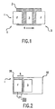
- Fig. 1 is a schematic view of film heat processor according to a first embodiment of the invention.
- the film heat processor 1 includes a continuous transport 2, such as an endless belt conveyor, for receiving a heat-developing film F at input I.
- the film F may either be manually loaded onto the continuous transport 2 or directly supplied thereto from a well known film exposure device, such as an imagesetter.
- the film may be, by way of example, a migration imaging film that can be developed using radiant energy.
- the continuous transport 2 conveys the film in the direction shown by arrow 4 past heaters 3 for developing. Since the heaters 3 are provided on opposite sides of the film F, only one heater is visible in the Fig. 1.
- the heaters 3 are configured so as to have an output that will minimize or eliminate thermal distortion of the film. Specifically, the heaters 3 are arranged to have a lower heat output at the ends of the heaters 3 (measured along a film conveying direction), and a higher heat output at a central portion thereof. With this arrangement, thermal distortion during the initial heating and cooling stages of the film at the heater input and output ends, respectively, is minimized.
- the heater output is profiled so that the film temperature is spatially constant along a direction perpendicular to the direction of movement of the film F.
- the desired heater output can be achieved in a number of ways by one familiar with the conventional art. Specific examples of heating arrangements for achieving the desired results are discussed next.
- heaters 3 each may comprise a plurality of convection 'ovens' serially arranged and maintained at different temperatures
- a preferred arrangement for heaters 3 instead includes the use of radiant heaters.
- Radiant heaters provide a more compact, less costly, and simpler arrangement for producing a desired heater output profile.
- Filters may be provided, where appropriate, to permit the radiant heater to be used with films sensitive to different light wavelengths.
- the material of the endless belt of the continuous transport 2 should be selected to have a low specific heat and good transparency so as to neither absorb nor impede the radiant energy.
- One such material may include Tefloncoated fiberglass.
- Specific radiant heaters may include, for example, etched foil heaters or fixed output heaters.
- the desired heat output profile may be obtained by changing the density of the serpentine pattern of the heating circuits of the heater. Specifically, an increase in density in a particular region of the heater will result in a corresponding increases in heat output for that region.
- fixed output radiant heaters can be used wherein heater panels of different output are arranged to achieve the desired affect. Thermal distortion of the film may also be controlled by controlling the relative movement between the film and the heaters.
- plural heaters 3 are disclosed in a superimposed relationship, it is also understood that a single heater, or a single heater in combination with a heat reflector, where the heater is on one side of the film F and the heat reflector is on the other side so as to substantially oppose one another, may instead be provided depending upon the particular application.
- the film F After being developed by the heaters 3, the film F is conveyed to the output O of the film heat processor 1. The film F may then be manually retrieved or delivered to an output tray (not shown).
- the film processor 1 is shown as having a conveying surface appropriately sized to the width of a single sheet of film, it is understood that the width of the conveying surface may be increased in order to permit a plurality of films to be simultaneously developed.
- the film heat processor 1 When the film heat processor 1 is combined with an exposure device, it may either be connected externally to the exposure device or be formed as an integral part of the exposure device as a single unit construction.
- a film buffer may be provided between the exposure device and the film processor in order to permit temporary accumulation of the film prior to developing.
- the continuous transport 2 is preferably driven with a speed at least as great as the speed at which the film travels through the exposure device in order to enhance productivity.
- Fig. 2 is a schematic view of film heat processor according to a second embodiment of the invention.
- the film heat processor 10 includes a reciprocating film transport 20 which reciprocates in the direction shown by arrow 5.
- the reciprocating film transport may comprise, for example, a fabric 21 stretched over a frame member.
- the fabric of the film transport is selected to have a low specific heat and good transparency so as not to impede or absorb the radiant energy emitted by the heaters 3.
- the frame member is reciprocated on rails (not shown) by a conventional reciprocating drive arrangement 22.
- a film is received on the reciprocating film transport 20 at input end I and is reciprocated past the heaters 3 (discussion of heaters 3 from this point on includes the alternative arrangements discussed with respect to the first embodiment), where it is developed, and then arrives at the other end of the reciprocating film transport 20.
- the developed film F may then be removed.
- the film transport 20 may receive film either manually or directly from an exposure device to which it is either externally connected or contained within.
- the second embodiment can provide an advantage in space savings over the first embodiment.
- the length of the film heat processor can be reduced along the film conveying direction by an amount substantially equal to the diameter of an endless belt roller.
- the width of the film transport 20 may be increased to accomodate a side by side arrangement of film sheets, thus permitting simultaneous development of a plurality of film sheets.
- Fig. 3 is a schematic view of a film heat processor according to a third embodiment of the invention.
- the embodiment of Fig. 3 differs from the second embodiment in that a reciprocating drive 23 is provided for reciprocating the heaters 3 parallel, but in a direction opposite to, the film conveying direction. Specifically, the heaters 3 are synchronized so as to directly oppose movement of the reciprocating film transport 20. Viewing Fig. 3, as the film F travels right to left, heaters 3 travel left to right. With this arrangement, the footprint of the film heat processor 30 is even further reduced over the prior embodiments.
- Fig. 4 is a schematic view of film heat processor 40 according to a fourth embodiment of the invention.
- Fig. 4 differs from the prior embodiments in that film F is stationary during developing.
- the film F is manually supplied to, and supported by, a stationary film support 41.
- the support 41 may comprise a fabric stretched over a frame member. Heaters 3 move from one end of the film support 41 across the film F to the dashed-line position shown in Fig. 4.
- Fig. 5 is a schematic view of film heat processor according to a fifth embodiment of the invention.
- the heat film processor 50 is similar to the embodiment of Fig. 1 except that a soft, or resiliently compliant, pinch roller 51 is provided for forming a nip with the continuous transport 2.
- the pinch roller 51 may be made resiliently compliant by providing the roller with a segmented outer surface, which is well known in the art. Trays 52 facilitate input and accumulation of the film sheets F. By providing a pinch roller 51, the length of the continuous transport 2 in the film feeding direction can be reduced since the leading edge of the inputted film will be sufficiently engaged with the continuous transport 2.
- Fig. 6 is a schematic view of film heat processor according to a sixth embodiment of the invention.
- the film heat processor 60 is similar to the first embodiment except that the continuous transport 2 is provided in an inclined position. Fences 61 are provided to maintain the film position on the continuous transport 2. With this arrangement, the footprint of the continuous film transport is reduced.
Landscapes
- Physics & Mathematics (AREA)
- General Physics & Mathematics (AREA)
- Photographic Developing Apparatuses (AREA)
- Non-Silver Salt Photosensitive Materials And Non-Silver Salt Photography (AREA)
- Processing And Handling Of Plastics And Other Materials For Molding In General (AREA)
Claims (10)
- Verfahren zum Entwickeln eines Films (F) durch Aufbringen von Wärme auf den Film (F) aus einer Erwärmungseinrichtung (3) mit den Schritten:dadurch gekennzeichnet, daß der Film (F) auf einer Endlosband-Fördereinrichtung (2) unterstützt wird.Unterstützen nur einer Seite des Films (F) auf einer Filmträgerfläche (2, 20, 41),Entwickeln des Films durch Aufbringen von Wärme aus der Erwärmungseinrichtung (3) auf die gesamte Oberfläche des Films (F), wobei sich die Erwärmungseinrichtung (3) in einer berührungslosen Beziehung zu dem Film (F) befindet, undVorsehen einer Relativbewegung zwischen der Filmträgerfläche (2, 20, 41) und der Erwärmungseinrichtung (3),
- Verfahren nach Anspruch 1, wobei der Schritt der Aufbringung von Wärme das Aufbringen von Strahlungsenergie auf den Film (F) umfaßt, so daß, entlang einer Richtung der Relativbewegung gemessen, eine höhere Wärmeleistung bei einem zentralen Abschnitt der Erwärmungseinrichtung (3) aufgebracht wird als an den Ende der Erwärmungseinrichtung (3) aufgebracht wird.
- Verfahren nach Anspruch 1, wobei die Relativbewegung zwischen der Filmträgerfläche (2, 20, 41) und der Erwärmungseinrichtung (3) eine Hin- und Herbewegung ist.
- Filmentwicklervorrichtung (1), welche umfaßt:eine Filmträgerfläche (2, 20, 41) zum Unterstützen nur einer Seite eines Films (F) darauf,Erwärmungseinrichtung (3), welche in einer berührungslosen Beziehung zu dem Film (F) zum Erwärmen der gesamten Oberfläche des Films (5) angeordnet ist, um diesen zu entwickeln, undeine Einrichtung, um im Gebrauch eine Relativbewegung zwischen der Erwärmungseinrichtung (3) und der Filmträgerfläche (2, 20, 41) zu bewirken, dadurch gekennzeichnet, daß die Filmträgeroberfläche eine Endlosband-Transporteinrichtung (2) ist.
- Filmentwicklervorrichtung (1) nach Anspruch 4, welche ferner einen Filmtransporteinrichtung (2, 20) zum Transportieren des Films (F) an der Erwärmungseinrichtung (3) vorbei umfaßt, wobei der Filmtransporteinrichtung (2, 20) die Filmträgerfläche enthält.
- Filmentwicklervorrichtung (1) nach Anspruch 5, wobei die Filmtransporteinrichtung (2, 20) in Bezug auf eine horizontale Richtung geneigt ist.
- Filmentwicklervorrichtung (1) nach Anspruch 6, wobei die Filmtransporteinrichtung (2, 20, 41) wenigstens einen Vorsprung (61) enthält, um eine Position eines auf der Filmtransporteinrichtung (2, 20) getragenen Films (F) beizubehalten.
- Filmentwicklervorrichtung (1) nach Anspruch 5 oder Anspruch 6, wobei die Filmtransporteinrichtung eine sich hin- und herbewegende Filmtransporteinrichtung (20) ist; und/oder wobei die Erwärmungseinrichtung (3) eine sich hin- und herbewegende Erwärmungseinrichtung (3) ist; und/oder wobei sich die Erwärmungseinrichtung (3) und die Filmtransporteinrichtung (2, 20) synchron in entgegengesetzte Richtungen bewegen.
- Filmentwicklervorrichtung (1) nach einem der Ansprüche 4 bis 8, wobei die Erwärmungseinrichtung (3) eine Oberflächenfläche wenigstens so groß wie die des zu entwickelnden Filmes (F) besitzt.
- Filmentwicklervorrichtung (1) nach einem der Ansprüche 4 bis 9, wobei die Erwärmungseinrichtung (3) wenigstens einen Heizstrahler umfaßt, welche entlang einer Relativbewegungsrichtung angeordnet ist, wobei der wenigstens eine Heizstrahler eine höhere Wärmeabgabeleistung an seinem zentralen Abschnitt als an den Enden des wenigstens einen Heizstrahlers besitzt.
Applications Claiming Priority (2)
| Application Number | Priority Date | Filing Date | Title |
|---|---|---|---|
| US434960 | 1995-05-04 | ||
| US08/434,960 US5587767A (en) | 1995-05-04 | 1995-05-04 | Digital film heat processor and method of developing digital film |
Publications (2)
| Publication Number | Publication Date |
|---|---|
| EP0741327A1 EP0741327A1 (de) | 1996-11-06 |
| EP0741327B1 true EP0741327B1 (de) | 2004-08-25 |
Family
ID=23726409
Family Applications (1)
| Application Number | Title | Priority Date | Filing Date |
|---|---|---|---|
| EP96303095A Expired - Lifetime EP0741327B1 (de) | 1995-05-04 | 1996-05-01 | Vorrichtung und Verfahren zur Filmentwicklung |
Country Status (4)
| Country | Link |
|---|---|
| US (1) | US5587767A (de) |
| EP (1) | EP0741327B1 (de) |
| JP (1) | JPH08320544A (de) |
| DE (1) | DE69633210T2 (de) |
Families Citing this family (15)
| Publication number | Priority date | Publication date | Assignee | Title |
|---|---|---|---|---|
| US5729271A (en) * | 1995-05-04 | 1998-03-17 | Xerox Corporation | Device to desensitize migration imaging film and allow daylight film handling |
| JP3614981B2 (ja) * | 1996-06-07 | 2005-01-26 | 富士写真フイルム株式会社 | 加熱装置 |
| US6278510B1 (en) | 1998-12-07 | 2001-08-21 | Eastman Kodak Company | System for optical writing to thermal film |
| US6048110A (en) * | 1998-12-07 | 2000-04-11 | Eastman Kodak Company | Compact thermal film apparatus with magnetic sensing device |
| US6062746A (en) * | 1998-12-07 | 2000-05-16 | Eastman Kodak Company | Compact apparatus for thermal film development and scanning |
| US6302599B1 (en) | 1999-09-01 | 2001-10-16 | Eastman Kodak Company | Thermal film camera with processing |
| US6174094B1 (en) | 1999-11-30 | 2001-01-16 | Eastman Kodak Company | Method and apparatus for photofinishing a photosensitive media and/or ordering of image products |
| CA2324701A1 (en) * | 1999-11-30 | 2001-05-30 | Eastman Kodak Company | Method and apparatus for photofinishing a photosensitive media and/or ordering of image products |
| US6398428B1 (en) | 2000-05-15 | 2002-06-04 | Eastman Kodak Company | Apparatus and method for thermal film development and scanning |
| US6464412B1 (en) | 2000-05-15 | 2002-10-15 | Eastman Kodak Company | Apparatus and method for radiant thermal film development |
| US6490023B1 (en) | 2000-06-13 | 2002-12-03 | Eastman Kodak Company | Processing apparatus and method for determining optimum processing characteristics of thermal developable film |
| US6365331B1 (en) | 2000-06-13 | 2002-04-02 | Eastman Kodak Company | Thermal film having at least two imaging layers with different processing characteristics and a method of forming and processing the same |
| US6369873B1 (en) * | 2000-06-13 | 2002-04-09 | Eastman Kodak Company | Thermal processing system and method including a kiosk |
| JP4720272B2 (ja) * | 2005-04-22 | 2011-07-13 | コニカミノルタエムジー株式会社 | シート状画像記録材料用トレー、シート状画像記録材料包装体 |
| WO2013031094A1 (ja) * | 2011-08-30 | 2013-03-07 | パナソニック株式会社 | 加熱装置 |
Family Cites Families (6)
| Publication number | Priority date | Publication date | Assignee | Title |
|---|---|---|---|---|
| JPS5330332B1 (de) * | 1971-05-06 | 1978-08-26 | ||
| DE2659486C2 (de) * | 1976-12-30 | 1978-12-07 | Hoechst Ag, 6000 Frankfurt | Entwicklungsvorrichtung zur Entwicklung von Diazokopiermaterialblättern |
| EP0184132B1 (de) * | 1984-11-30 | 1990-04-11 | Fuji Photo Film Co., Ltd. | Thermisches Aufzeichnungsgerät |
| US4977422A (en) * | 1986-06-06 | 1990-12-11 | Visicon, Inc. | Apparatus for transporting flat sheets, especially photosensitive sheet materials |
| JPS63228156A (ja) * | 1987-03-17 | 1988-09-22 | Konica Corp | 熱現像機のカ−ル防止装置 |
| US5352863A (en) * | 1992-04-03 | 1994-10-04 | Minnesota Mining And Manufacturing Company | Flat bed thermophotographic film processor |
-
1995
- 1995-05-04 US US08/434,960 patent/US5587767A/en not_active Expired - Lifetime
-
1996
- 1996-04-26 JP JP8106528A patent/JPH08320544A/ja not_active Withdrawn
- 1996-05-01 EP EP96303095A patent/EP0741327B1/de not_active Expired - Lifetime
- 1996-05-01 DE DE69633210T patent/DE69633210T2/de not_active Expired - Lifetime
Also Published As
| Publication number | Publication date |
|---|---|
| JPH08320544A (ja) | 1996-12-03 |
| EP0741327A1 (de) | 1996-11-06 |
| US5587767A (en) | 1996-12-24 |
| DE69633210T2 (de) | 2005-01-20 |
| DE69633210D1 (de) | 2004-09-30 |
Similar Documents
| Publication | Publication Date | Title |
|---|---|---|
| EP0741327B1 (de) | Vorrichtung und Verfahren zur Filmentwicklung | |
| EP1533263B1 (de) | Förderband | |
| JP3384707B2 (ja) | 画像形成装置 | |
| US5975772A (en) | Thermal developing apparatus | |
| JPS5840176B2 (ja) | フイルム現像および定着装置 | |
| US5869806A (en) | Apparatus and method for thermally processing an imaging material employing means for bending the imaging material during thermal processing | |
| US5669032A (en) | Constrained film heat processor and method of developing digital film using conduction heat transfer | |
| EP0877971B1 (de) | Vorrichtung und verfahren zur abkühlung von thermisch entwickelbarem material | |
| US5634167A (en) | Constrained film heat processor and method of developing digital film using radiant heat transfer | |
| US6051813A (en) | Method for thermally processing an imaging material employing improved heating means | |
| US5790069A (en) | Thermal Processor with air flow preventing structure | |
| EP0864944A1 (de) | Thermische Entwicklungsvorrichtung | |
| US7108433B2 (en) | Thermal processor employing varying roller spacing | |
| US5644379A (en) | Passive belt guidance by fabric weave orientation | |
| JP2004046158A (ja) | トナーを基板上に定着させるための方法及び装置 | |
| JP2004078045A (ja) | 定着装置及び該定着装置を有する画像形成装置 | |
| US7283144B2 (en) | Heat developing apparatus and heat developing method | |
| EP0483805A1 (de) | Bilderzeugungsvorrichtung | |
| US7043186B2 (en) | Fixing station and method for the uniform fixing of toner images on a carrier material with the aid of a movable covering device | |
| JPH1127458A (ja) | 画像読取方法 | |
| US5986238A (en) | Apparatus and method for thermally processing an imaging material employing means for reducing fogging on the imaging material during thermal processing | |
| JPH11218893A5 (de) | ||
| KR930005359B1 (ko) | 칼라 비디오 프린터 열정착부의 수상지 받침대 장치 | |
| JPH0526589Y2 (de) | ||
| US6115102A (en) | Light-sensitive material transporting device |
Legal Events
| Date | Code | Title | Description |
|---|---|---|---|
| PUAI | Public reference made under article 153(3) epc to a published international application that has entered the european phase |
Free format text: ORIGINAL CODE: 0009012 |
|
| AK | Designated contracting states |
Kind code of ref document: A1 Designated state(s): DE FR GB |
|
| 17P | Request for examination filed |
Effective date: 19970506 |
|
| 17Q | First examination report despatched |
Effective date: 20010911 |
|
| GRAP | Despatch of communication of intention to grant a patent |
Free format text: ORIGINAL CODE: EPIDOSNIGR1 |
|
| GRAS | Grant fee paid |
Free format text: ORIGINAL CODE: EPIDOSNIGR3 |
|
| GRAA | (expected) grant |
Free format text: ORIGINAL CODE: 0009210 |
|
| AK | Designated contracting states |
Kind code of ref document: B1 Designated state(s): DE FR GB |
|
| REG | Reference to a national code |
Ref country code: GB Ref legal event code: FG4D |
|
| REF | Corresponds to: |
Ref document number: 69633210 Country of ref document: DE Date of ref document: 20040930 Kind code of ref document: P |
|
| ET | Fr: translation filed | ||
| PLBE | No opposition filed within time limit |
Free format text: ORIGINAL CODE: 0009261 |
|
| STAA | Information on the status of an ep patent application or granted ep patent |
Free format text: STATUS: NO OPPOSITION FILED WITHIN TIME LIMIT |
|
| 26N | No opposition filed |
Effective date: 20050526 |
|
| PGFP | Annual fee paid to national office [announced via postgrant information from national office to epo] |
Ref country code: GB Payment date: 20140425 Year of fee payment: 19 |
|
| PGFP | Annual fee paid to national office [announced via postgrant information from national office to epo] |
Ref country code: DE Payment date: 20140424 Year of fee payment: 19 |
|
| PGFP | Annual fee paid to national office [announced via postgrant information from national office to epo] |
Ref country code: FR Payment date: 20140521 Year of fee payment: 19 |
|
| REG | Reference to a national code |
Ref country code: DE Ref legal event code: R119 Ref document number: 69633210 Country of ref document: DE |
|
| GBPC | Gb: european patent ceased through non-payment of renewal fee |
Effective date: 20150501 |
|
| REG | Reference to a national code |
Ref country code: FR Ref legal event code: ST Effective date: 20160129 |
|
| PG25 | Lapsed in a contracting state [announced via postgrant information from national office to epo] |
Ref country code: DE Free format text: LAPSE BECAUSE OF NON-PAYMENT OF DUE FEES Effective date: 20151201 Ref country code: GB Free format text: LAPSE BECAUSE OF NON-PAYMENT OF DUE FEES Effective date: 20150501 |
|
| PG25 | Lapsed in a contracting state [announced via postgrant information from national office to epo] |
Ref country code: FR Free format text: LAPSE BECAUSE OF NON-PAYMENT OF DUE FEES Effective date: 20150601 |