EP0483805A1 - Bilderzeugungsvorrichtung - Google Patents
Bilderzeugungsvorrichtung Download PDFInfo
- Publication number
- EP0483805A1 EP0483805A1 EP19910118527 EP91118527A EP0483805A1 EP 0483805 A1 EP0483805 A1 EP 0483805A1 EP 19910118527 EP19910118527 EP 19910118527 EP 91118527 A EP91118527 A EP 91118527A EP 0483805 A1 EP0483805 A1 EP 0483805A1
- Authority
- EP
- European Patent Office
- Prior art keywords
- pressure
- heat developing
- transfer
- heating
- photosensitive member
- Prior art date
- Legal status (The legal status is an assumption and is not a legal conclusion. Google has not performed a legal analysis and makes no representation as to the accuracy of the status listed.)
- Withdrawn
Links
Images



Classifications
-
- G—PHYSICS
- G03—PHOTOGRAPHY; CINEMATOGRAPHY; ANALOGOUS TECHNIQUES USING WAVES OTHER THAN OPTICAL WAVES; ELECTROGRAPHY; HOLOGRAPHY
- G03G—ELECTROGRAPHY; ELECTROPHOTOGRAPHY; MAGNETOGRAPHY
- G03G15/00—Apparatus for electrographic processes using a charge pattern
- G03G15/06—Apparatus for electrographic processes using a charge pattern for developing
- G03G15/08—Apparatus for electrographic processes using a charge pattern for developing using a solid developer, e.g. powder developer
- G03G15/095—Removing excess solid developer, e.g. fog preventing
-
- G—PHYSICS
- G03—PHOTOGRAPHY; CINEMATOGRAPHY; ANALOGOUS TECHNIQUES USING WAVES OTHER THAN OPTICAL WAVES; ELECTROGRAPHY; HOLOGRAPHY
- G03B—APPARATUS OR ARRANGEMENTS FOR TAKING PHOTOGRAPHS OR FOR PROJECTING OR VIEWING THEM; APPARATUS OR ARRANGEMENTS EMPLOYING ANALOGOUS TECHNIQUES USING WAVES OTHER THAN OPTICAL WAVES; ACCESSORIES THEREFOR
- G03B27/00—Photographic printing apparatus
- G03B27/32—Projection printing apparatus, e.g. enlarger, copying camera
-
- G—PHYSICS
- G03—PHOTOGRAPHY; CINEMATOGRAPHY; ANALOGOUS TECHNIQUES USING WAVES OTHER THAN OPTICAL WAVES; ELECTROGRAPHY; HOLOGRAPHY
- G03F—PHOTOMECHANICAL PRODUCTION OF TEXTURED OR PATTERNED SURFACES, e.g. FOR PRINTING, FOR PROCESSING OF SEMICONDUCTOR DEVICES; MATERIALS THEREFOR; ORIGINALS THEREFOR; APPARATUS SPECIALLY ADAPTED THEREFOR
- G03F7/00—Photomechanical, e.g. photolithographic, production of textured or patterned surfaces, e.g. printing surfaces; Materials therefor, e.g. comprising photoresists; Apparatus specially adapted therefor
- G03F7/002—Photomechanical, e.g. photolithographic, production of textured or patterned surfaces, e.g. printing surfaces; Materials therefor, e.g. comprising photoresists; Apparatus specially adapted therefor using materials containing microcapsules; Preparing or processing such materials, e.g. by pressure; Devices or apparatus specially designed therefor
- G03F7/0022—Devices or apparatus
-
- G—PHYSICS
- G03—PHOTOGRAPHY; CINEMATOGRAPHY; ANALOGOUS TECHNIQUES USING WAVES OTHER THAN OPTICAL WAVES; ELECTROGRAPHY; HOLOGRAPHY
- G03B—APPARATUS OR ARRANGEMENTS FOR TAKING PHOTOGRAPHS OR FOR PROJECTING OR VIEWING THEM; APPARATUS OR ARRANGEMENTS EMPLOYING ANALOGOUS TECHNIQUES USING WAVES OTHER THAN OPTICAL WAVES; ACCESSORIES THEREFOR
- G03B2227/00—Photographic printing apparatus
- G03B2227/32—Projection printing apparatus, e.g. enlarging apparatus, copying camera
- G03B2227/325—Microcapsule copiers
Definitions
- the present invention relates to copiers, printers and other image forming devices that produce images by using a photosensitive transfer type heat developing material, and more particularly it relates to heat developing and pressure transfer devices for developing the material by means of heat and transferring the image by using pressure, respectively.
- JP-A-62-147461 A prior art example of an image forming device that uses a photosensitive transfer type heat developing material is disclosed in JP-A-62-147461.
- a regular pressure roller is used in examples that perform pressure transfer while heating.
- pressure 15 usually applied by passing the image and a transfer medium through the nip between rigid metal pressure rollers.
- JP-A-62-232653 discloses that pressure may be reduced and a more compact device may be achieved if a heating device is added to the pressure transfer device.
- the heat developing mechanism and the pressure transfer mechanism are configured separately and each is controlled at its own temperature, when the two are in proximity to each other, each is affected by the temperature of the other, thus requiring time until they stabilize, during which image quality suffers. Further, external disturbances can destabilize temperature control, also affecting image quality.
- the invention is intended to solve the above problems, and its purpose is to offer a low cost image forming device that is compact and lightweight and can easily and consistently produce high quality images.
- the photosensitive member used in the image forming device of the invention may be a support member on which microcapsules are applied that contain a photosensitive silver halide, reducing agents, polymer compounds, and coloring materials such as disclosed in JP-A-61-275742, for example.
- the temperature for heat developing this type of photosensitive member should be 120°-180°C.
- sufficient image quality can basically be achieved at room temperature, but, as already noted, the pressure can be reduced if heating is simultaneously performed. Experiments showed that the pressure could be reduced to from one-half to one-third that at room temperature by heating to 50°-100°C.
- the same heat source is used for heat developing and pressure transfer in order to achieve the above purpose, and basically it is configured with a suitable temperature difference between heat developing and pressure transfer.
- a good image could be obtained by further raising the heating temperature for pressure transfer so that the heating temperature for heat developing and that for pressure transfer were nearly the same.
- one embodiment of the image forming device of the invention performs heat developing and heat transfer at nearly the same temperature.
- Fig. 1 is a front cross section of an embodiment in which the image forming device of the invention is a copier. First, the operation of the machine is explained. In this embodiment, the same heat source is used for heating both in heat developing and in pressure transfer.
- An original 2 is set on an original table 1 which is movable in the direction of arrow A in the Figure.
- a red lamp 3 a green lamp 4 and a blue lamp 5, which serve as light sources, irradiates the original 2
- the light reflected from the original 2 passes through a lens 6 and forms an image on a photosensitive member 8 that moves on top of an exposure table 7, these elements thus forming a so-called "scan exposure system”.
- the photosensitive member 8 which is fed out continuously in the form of a sheet from a cartridge 20 where the undeveloped photosensitive member 8 is housed, is exposed on the exposure table 7 to have a latent image formed on it, after which it undergoes heat developing in a heat developer 30.
- a transfer member 11 stored in a paper supply tray 10 in the form of cut sheets is fed out by a paper supply device 12, is registered with the area of the photosensitive member 8 where the image has been formed, and the two are pressed together in a roller pressure type pressure transfer device 60 to transfer the image to the transfer member 11.
- the pressure part of the pressure transfer device 60 comprises an upper pressure roller 61, a middle pressure roller 62 and a lower pressure roller 63, and pressure transfer is performed between the upper pressure roller 61 and the middle pressure roller 62.
- the transfer member 11 is then separated from the photosensitive member 8 by a separation roller 64, passes through transport roller means 13 and is discharged into a paper tray 14, while the photosensitive member 8 travels past a pinch roller 65, which transports and assists separation, and is wound up on a take up shaft 21.
- 15 is a manual paper feed entrance and 16 is a gas filter for removing gas generated in the machine.
- the photosensitive member 8, on which the latent image has been formed undergoes heat developing by moving over a heat developing roller 31 which makes up the heat developing device 30.
- the heat developing roller 31 which is made from a hollow aluminum pipe with a 20 mm outside diameter, houses a halogen lamp with a rated output power of 300 W as the heater 32 and heats the photosensitive member 8 from the back side (side opposite to the latent image).
- the transfer member 11 fed from the paper supply device is lined up against the image area on the photosensitive member 8, and the middle pressure roller 62 and the lower pressure roller 63 move in the direction of arrow B and press the photosensitive member 8 and the transfer member 11 between the middle pressure roller 62 and the upper pressure roller 61. While this is happening, the steel upper pressure roller 61 with an outside diameter of 60 mm is in contact with the heat developing roller 31 to be heated by the latter and to heat the photosensitive member 8 and the transfer member 11.
- the temperature of the upper pressure roller 61 can be changed from near room temperature to nearly the developing temperature without changing the developing temperature, thus facilitating pressure transfer at an appropriate temperature according to the characteristics of the photosensitive member 8 used.
- the heat developing temperature can be appropriately controlled by controlling the power to the heater 32. According to experiments in which a number of heat developing temperatures were tried, the difference between the heat developing temperature and the pressure transfer temperature was generally 20° to 30°C.
- the photosensitive member 8 is separated from the transfer member 11 by the separation roller 64, passes the pinch roller 65 and is wound up on the take up shaft 21, and while pressure transfer is being performed, the pinch roller 65 moves in the direction of arrow C and is pushed against the upper pressure roller 61 to ensure that the photosensitive member is reliably transported.
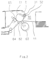
- Fig. 3 is a front cross section showing another embodiment in which pressure transfer and heat developing are performed using the same heat source.
- the photosensitive member 8, on which the latent image has been formed undergoes heat developing as it passes by a half-moon shaped heater 33. Together with the transfer member it is then sandwiched between the upper pressure roller 61 and the middle pressure roller 62 where pressure transfer is performed.
- the upper pressure roller 61 is heated by the radiant heat from the heater 33.
- a heat blocking plate 34 is movable in the direction of arrow D between the heater 33 and the upper pressure roller 61 to change the area on the upper pressure roller 61 irradiated by the heat from the heater 33, whereby the temperature of the upper pressure 61 can be controlled in real time so that a more accurate pressure transfer temperature can be maintained.
- heat developing device 30 and the pressure transfer device 60 in an embodiment in which heat developing and pressure transfer are performed at the same temperature, which is a feature of one embodiment of the invention. Also in this embodiment, the same heat source is used for heating in heat developing and pressure transfer.
- Fig. 4 is a front cross section showing an embodiment of a pressure transfer device that also performs heat developing.
- a halogen lamp heater 66 is housed inside the hollow upper pressure roller 61, and a temperature sensor 67 is provided on the upper pressure roller 61 to facilitate control at the prescribed temperature.
- the mechanism for heat developing is not separate, but rather it is implemented by running the photosensitive member 8 along the upper pressure roller 61, which is one of the rollers by which pressure transfer is performed.
- the area in which heat developing is performed is the hatched area in the Figure, and heat developing and pressure transfer are processed continuously at nearly the same temperature. Therefore, the heating mechanism is extremely simple, transport of the photosensitive member 8 can be performed reliably and the quality of the output image is consistent.
- the pressure in pressure transfer can be reduced somewhat even at temperatures below this, but this greatly increases developing time. This is because the action of the reaction accelerator contained in the photosensitive member 8 is impeded. A reaction accelerator with a small activation energy can be used to prevent this, but then the shelf life of the photosensitive member 8 is sacrificed.
- the pressure used in pressure transfer can be lowered as the heating temperature is raised and the heating time for heat developing is shortened, but then the heat resistance of the photosensitive member 8 Presents a problem.
- a thin PET film is generally used as the support member because of its low cost, wide applicability, heat conduction and other advantages. This film, however, is not highly resistant to heat and is difficult to handle. Further, when high temperatures are used, the materials, control, cost and other factors concerning the heating mechanism itself add further restrictions, and therefore the temperature cannot be made too high.
- the temperature conditions for heat developing and pressure transfer are nearly the same and basically cannot be changed, but if the characteristics of the photosensitive member 8 require it, the transport speed of the photosensitive member 8, the angle at which the photosensitive member 8 is wound around the upper pressure roller 61 or the diameter of the upper pressure roller 61 can be changed without changing the heating temperature, thus making it possible to achieve the necessary heating conditions for heat developing.
- Fig. 5 is a front cross section of another embodiment of the heat developing device 30 and pressure transfer device 60.
- the heating mechanism for heat developing and pressure transfer are independent.
- the hollow upper pressure roller 61 in the Figure contains a halogen lamp heater 66 as the heat source.
- the heat developing device 30 is provided with another heater, not shown, in order to maintain its temperature nearly equal to that of the pressure transfer device 60, and since both are at the same temperature, they affect each other very little even when positioned close to each other as in this embodiment, thus making it possible to maintain a stable temperature over long periods. Further, since the photosensitive member 8 arrives at the pressure transfer device 60 immediately after undergoing heat developing in the heat developing device 30 and it undergoes heat transfer at nearly the same temperature, almost no thermal expansion or contraction occurs during this time, thus reducing the likelihood of the occurrence of wrinkles which cause uneven developing and poor transfer.
- halogen lamp heater instead of a halogen lamp heater, various types of heat sources can be used such as a ceramic heater, nichrome and other heating resistor elements.
- Fig. 6 is a developed cross section of the upper pressure roller 61 whose surface is covered with rubber 68, which is a plastic material.
- rubber 68 which is a plastic material.
- the roller is hollow as in this embodiment, it is technologically difficult to improve the cylindricality of the roller, but by covering the surface of the roller with a material that is sufficiently soft compared to metal, such as rubber or plastic, shape defects can be absorbed by this material, thus making the pressure distribution in pressure transfer uniform and making it easier to suppress uneven density and wrinkles.
- silicon rubber was coated in a thickness of 0.1 mm on the surface of the upper pressure roller 61 in this embodiment, a sharp image output was obtained.
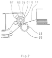
- Fig. 7 shows an embodiment in which the surfaces of both the upper pressure roller 61 and the lower pressure roller 63 were coated with a urethane rubber 69.
- the surfaces of both the upper pressure roller 61 and the lower pressure roller 63 were covered with a 2 mm thick urethane rubber 69, the upper pressure roller 61 was controlled at 80°C, and the pressing force was 3000 N (300 kgf) for an A4 width, whereby good results were obtained.
- silicon rubber and urethane rubber were used as the plastic material on the surface of the rollers, but of course the invention is not limited to these, and other rubber or plastic materials can be used as long as they have a certain amount of heat resistance and easily undergo plastic deformation.
- the pressure used is not sufficiently low in relatively low temperature ranges, the pressure rollers themselves must be made from an alloy or other material with sufficient rigidity, but in the higher temperature ranges, the pressure can be low, thus facilitating the use of rubber, plastic or other plastic materials for the entire pressure roller.
- contact heating was used by the heating mechanism for both heat developing and pressure transfer, but the invention is not limited to this, and radiant heating, hot air heating, induction heating, resistance heating or any combination of these can be employed.
- pressure can be applied in the pressure transfer system by the reciprocating or circulating action of a small roller, and instead of a roller pressure system, impact or ultrasound vibration can be used.
- a copier was used here to explain the invention, but the invention is not limited to this, and it can be applied to printers, facsimile machines, electronic cameras and image forming devices in general.
Landscapes
- Physics & Mathematics (AREA)
- General Physics & Mathematics (AREA)
- Photographic Developing Apparatuses (AREA)
Applications Claiming Priority (6)
| Application Number | Priority Date | Filing Date | Title |
|---|---|---|---|
| JP29601190 | 1990-11-01 | ||
| JP296011/90 | 1990-11-01 | ||
| JP52088/91 | 1991-03-18 | ||
| JP5208891 | 1991-03-18 | ||
| JP194280/91 | 1991-08-02 | ||
| JP3194280A JPH05204119A (ja) | 1990-11-01 | 1991-08-02 | 画像形成装置 |
Publications (1)
| Publication Number | Publication Date |
|---|---|
| EP0483805A1 true EP0483805A1 (de) | 1992-05-06 |
Family
ID=27294544
Family Applications (1)
| Application Number | Title | Priority Date | Filing Date |
|---|---|---|---|
| EP19910118527 Withdrawn EP0483805A1 (de) | 1990-11-01 | 1991-10-30 | Bilderzeugungsvorrichtung |
Country Status (4)
| Country | Link |
|---|---|
| US (1) | US5166724A (de) |
| EP (1) | EP0483805A1 (de) |
| JP (1) | JPH05204119A (de) |
| KR (1) | KR920010369A (de) |
Families Citing this family (3)
| Publication number | Priority date | Publication date | Assignee | Title |
|---|---|---|---|---|
| US5502532A (en) * | 1994-05-23 | 1996-03-26 | Biesinger; Mark G. | Method and system for processing film by speed and activating agent concentration temperature control |
| JP3626302B2 (ja) * | 1996-12-10 | 2005-03-09 | Jsr株式会社 | 光硬化性樹脂組成物 |
| DE102005010272A1 (de) | 2005-03-03 | 2006-09-14 | Infineon Technologies Ag | Halbleiterbauelement sowie Verfahren zum Herstellen eines Halbleiterbauelements |
Citations (3)
| Publication number | Priority date | Publication date | Assignee | Title |
|---|---|---|---|---|
| US4799085A (en) * | 1986-04-03 | 1989-01-17 | Fuji Photo Film Co., Ltd. | Image recording apparatus and method |
| US4841339A (en) * | 1987-03-12 | 1989-06-20 | Fuji Photo Film Co., Ltd. | Image forming method |
| US4942420A (en) * | 1988-01-22 | 1990-07-17 | Brother Kogyo Kabushiki Kaisha | Heat/pressure applying unit for copying apparatus |
Family Cites Families (6)
| Publication number | Priority date | Publication date | Assignee | Title |
|---|---|---|---|---|
| US4864356A (en) * | 1987-04-21 | 1989-09-05 | Brother Kogyo Kabushiki Kaisha | Exposure device for image recording apparatus |
| US4910550A (en) * | 1987-08-07 | 1990-03-20 | Sharp Kabushiki Kaisha | Image formation apparatus with supplemental light source |
| EP0354691A3 (de) * | 1988-08-09 | 1991-05-29 | Seiko Epson Corporation | Bildaufzeichnungsvorrichtung |
| US4992816A (en) * | 1988-09-09 | 1991-02-12 | Fuji Photo Film Co., Ltd. | Image recording apparatus and method |
| JPH0335542U (de) * | 1989-08-17 | 1991-04-08 | ||
| JPH03139634A (ja) * | 1989-10-26 | 1991-06-13 | Brother Ind Ltd | 画像形成装置 |
-
1991
- 1991-08-02 JP JP3194280A patent/JPH05204119A/ja active Pending
- 1991-10-29 KR KR1019910019019A patent/KR920010369A/ko not_active Withdrawn
- 1991-10-29 US US07/784,495 patent/US5166724A/en not_active Expired - Lifetime
- 1991-10-30 EP EP19910118527 patent/EP0483805A1/de not_active Withdrawn
Patent Citations (3)
| Publication number | Priority date | Publication date | Assignee | Title |
|---|---|---|---|---|
| US4799085A (en) * | 1986-04-03 | 1989-01-17 | Fuji Photo Film Co., Ltd. | Image recording apparatus and method |
| US4841339A (en) * | 1987-03-12 | 1989-06-20 | Fuji Photo Film Co., Ltd. | Image forming method |
| US4942420A (en) * | 1988-01-22 | 1990-07-17 | Brother Kogyo Kabushiki Kaisha | Heat/pressure applying unit for copying apparatus |
Also Published As
| Publication number | Publication date |
|---|---|
| US5166724A (en) | 1992-11-24 |
| JPH05204119A (ja) | 1993-08-13 |
| KR920010369A (ko) | 1992-06-26 |
Similar Documents
| Publication | Publication Date | Title |
|---|---|---|
| JPH103231A (ja) | 一様なニップ速度のロール定着装置 | |
| EP0320973A2 (de) | Glanzmaschine für Bilder | |
| US4933724A (en) | Fixing device for electrophotography | |
| EP0601879A2 (de) | Fixiervorrichtung mit Blattkrümmungskompensation | |
| JP2003149983A (ja) | 画像形成装置 | |
| JPH06314041A (ja) | 加熱装置、画像形成装置、及び加熱体 | |
| JPH1195582A (ja) | ベルト式定着装置 | |
| US5166724A (en) | Image printer/copier with a common heater for development and transfer pressure of latent images on microcapsule mediums | |
| JP2005031550A (ja) | 定着装置の通紙制御方法 | |
| JPH06186871A (ja) | 画像形成装置 | |
| JPH08115004A (ja) | 定着装置 | |
| JP3750894B2 (ja) | 画像記録装置 | |
| JPH06345292A (ja) | 加熱装置及び画像形成装置 | |
| JPH0816028A (ja) | 定着装置 | |
| JPH1124180A (ja) | 原稿載置台 | |
| JPH11174896A (ja) | 定着装置及び定着装置の温度制御方法 | |
| JPS6243314Y2 (de) | ||
| JP2955694B2 (ja) | 熱現像装置及びこれを備えた画像形成装置 | |
| JPH0863019A (ja) | 加熱装置及び画像形成装置 | |
| JPH06348157A (ja) | 加熱装置及び画像形成装置 | |
| JP2582172B2 (ja) | 複数の光学系を有する複写機 | |
| JP2952792B2 (ja) | 熱現像装置及びこれを備えた画像形成装置 | |
| JP2002211823A (ja) | 画像形成装置 | |
| JPH0545853A (ja) | 画像形成方法 | |
| JP2000250192A (ja) | 熱処理装置及びそれを利用した熱現像装置 |
Legal Events
| Date | Code | Title | Description |
|---|---|---|---|
| PUAI | Public reference made under article 153(3) epc to a published international application that has entered the european phase |
Free format text: ORIGINAL CODE: 0009012 |
|
| AK | Designated contracting states |
Kind code of ref document: A1 Designated state(s): DE FR GB |
|
| RIN1 | Information on inventor provided before grant (corrected) |
Inventor name: ASAWA, HIROSI Inventor name: NOMURA, YUJIRO Inventor name: KOBAYASHI, ATSUSHI |
|
| STAA | Information on the status of an ep patent application or granted ep patent |
Free format text: STATUS: THE APPLICATION IS DEEMED TO BE WITHDRAWN |
|
| 18D | Application deemed to be withdrawn |
Effective date: 19920911 |