EP0742665A2 - Verfahren und Vorrichtung zur Synchronisierung des Polarisierungsteuersignales einer wechselstrompolarisierter Lichtbogenentladungslampe mit der Beleuchtungszeitsignale eines CCD-Zeilensensors - Google Patents
Verfahren und Vorrichtung zur Synchronisierung des Polarisierungsteuersignales einer wechselstrompolarisierter Lichtbogenentladungslampe mit der Beleuchtungszeitsignale eines CCD-Zeilensensors Download PDFInfo
- Publication number
- EP0742665A2 EP0742665A2 EP96105750A EP96105750A EP0742665A2 EP 0742665 A2 EP0742665 A2 EP 0742665A2 EP 96105750 A EP96105750 A EP 96105750A EP 96105750 A EP96105750 A EP 96105750A EP 0742665 A2 EP0742665 A2 EP 0742665A2
- Authority
- EP
- European Patent Office
- Prior art keywords
- line
- ccd
- discharge lamp
- arc
- scan line
- Prior art date
- Legal status (The legal status is an assumption and is not a legal conclusion. Google has not performed a legal analysis and makes no representation as to the accuracy of the status listed.)
- Granted
Links
Images


Classifications
-
- H—ELECTRICITY
- H04—ELECTRIC COMMUNICATION TECHNIQUE
- H04N—PICTORIAL COMMUNICATION, e.g. TELEVISION
- H04N1/00—Scanning, transmission or reproduction of documents or the like, e.g. facsimile transmission; Details thereof
- H04N1/40—Picture signal circuits
- H04N1/40056—Circuits for driving or energising particular reading heads or original illumination means
-
- H—ELECTRICITY
- H04—ELECTRIC COMMUNICATION TECHNIQUE
- H04N—PICTORIAL COMMUNICATION, e.g. TELEVISION
- H04N1/00—Scanning, transmission or reproduction of documents or the like, e.g. facsimile transmission; Details thereof
- H04N1/04—Scanning arrangements, i.e. arrangements for the displacement of active reading or reproducing elements relative to the original or reproducing medium, or vice versa
- H04N1/19—Scanning arrangements, i.e. arrangements for the displacement of active reading or reproducing elements relative to the original or reproducing medium, or vice versa using multi-element arrays
- H04N1/191—Scanning arrangements, i.e. arrangements for the displacement of active reading or reproducing elements relative to the original or reproducing medium, or vice versa using multi-element arrays the array comprising a one-dimensional [1D] array
- H04N1/192—Simultaneously or substantially simultaneously scanning picture elements on one main scanning line
- H04N1/193—Simultaneously or substantially simultaneously scanning picture elements on one main scanning line using electrically scanned linear arrays, e.g. linear CCD arrays
Definitions
- the present invention relates in general to scanning systems incorporating a light sensitive sensor arrangement such as a mono- or polychrome CCD (charge coupled device) line sensor. More particularly, the present invention is directed to a method and apparatus for synchronizing the polarization control signal of an AC-polarized arc-discharge lamp with the color channel exposure timing signals of a CCD line sensor.
- a light sensitive sensor arrangement such as a mono- or polychrome CCD (charge coupled device) line sensor.
- CCD charge coupled device
- High efficiency AC-polarized arc-discharge lamps such as metal-halide and medium source rare earth arc-discharge lamps, are quasi-point light sources which provide a high color temperature over a wide power range, especially in the blue color where CCD sensors commonly have a lower spectral responsivity.
- arc-discharge lamps are driven by a periodic signal (e.g., a square wave) to balance the thermal dissipation of the electrodes within the lamp.
- a periodic signal e.g., a square wave
- the polarization of the discharge between the electrodes of the lamp causes deleterious line-wise brightness variations on the target being scanned which are transferred to the scanned image. Since the human eye and brain are highly capable of detecting such line-wise brightness variations on the scanned image, arc-discharge lamps have heretofore not been incorporated into scanning systems.
- the present invention provides a method and apparatus for substantially eliminating the line-wise brightness variations on an image being scanned associated with the utilization of an AC-polarized arc-discharge lamp in a scanning system. Specifically, the present invention provides a method and apparatus for synchronizing the polarization control signal of an AC-polarized arc-discharge lamp system with the color channel exposure timing signals of a CCD line sensor.
- the advantages afforded by the present invention are more easily understood by first analyzing the output of a scanning system incorporating a polychrome CCD line sensor and an AC-polarized arc-discharge lamp, wherein the polarization control signal of the AC-polarized arc-discharge lamp is not synchronized with the color channel exposure timing signals of the polychrome CCD line sensor.
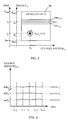
- a neutral document (ND) 10 is being scanned in a line-wise manner by an "unsynchronized" scanning system (not shown) including a polychrome CCD line sensor and an AC-polarized arc-discharge lamp.
- the polychrome CCD line sensor scans the neutral document 10 in a line-wise manner, providing scanning data for a series of scan lines (e.g., line i-1, line i, line i+1) between positions pstart (tstart) and pstop (tstop).
- a series of scan lines e.g., line i-1, line i, line i+1
- the exposure of each color channel of an ideal polychrome CCD line sensor should remain constant when scanning a neutral document.
- line-wise brightness variations on the neutral document 10 being scanned produced by the instability of the AC-polarized arc-discharge lamp, result in time varying channel exposures.
- the signal level S CHj (x, y) generally varies across the thousands of individual CCD elements forming each color channel of a conventional CCD line sensor. Accordingly, as known in the art, the relationship defined by EQU. 2 is typically achieved by electronically equalizing the output signals of the CCD line sensor (e.g., under software control).
- EXP j (t i ) ⁇ exp j ⁇ visual B( ⁇ ,t)D( ⁇ ,t)OE( ⁇ )CH( ⁇ )d ⁇ dt
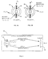
- an AC-polarized arc-discharge lamp 12 generally includes a pair of electrodes 14, 14' which interchangeably serve as the cathode or anode of the lamp, depending upon the polarity of the driving voltage V lamp .
- electrodes 14 and 14' serve as the cathode (emission) and anode (reception), respectively, of the lamp 12, given a driving current I lamp+ .
- the highest brightness produced by the lamp is localized in the vicinity of the cathode, electrode 14.
- electrodes 14 and 14' serve as the anode (reception) and cathode (emission), respectively, of the lamp 12.
- the highest brightness produced by the lamp is localized in the area of the cathode, electrode 14'.
- the location of highest brightness produced by an AC-polarized arc-discharge lamp varies in response to the polarity of the driving current I lamp , and: LO + ( ⁇ ) ⁇ LO - ( ⁇ )
- the target 18 being scanned generally corresponds to an actual document if a reflective original is being scanned, or to a diffuse screen if a transmissive original is being scanned. Accordingly, the light coupling efficiency of the AC-polarized arc-discharge lamp 12, when driven by a current I lamp+ (FIG. 3A), is not equivalent to the light coupling efficiency of the lamp when driven by a current I lamp- (FIG. 3B). Namely: LCE + ( ⁇ ) ⁇ LCE - ( ⁇ )
- B( ⁇ , t) LO( ⁇ ,t) ⁇ LCE( ⁇ ,t)
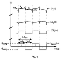
- FIG. 5 The effects of an alternating driving current I lamp on the brightness B( ⁇ , t), light output LO( ⁇ , t) and light coupling efficiency LCE( ⁇ , t) of a typical AC-polarized arc-discharge lamp are illustrated in FIG. 5. As shown, the brightness B( ⁇ , t), light output LO( ⁇ , t) and light coupling efficiency LCE( ⁇ , t) of the AC-polarized arc-discharge lamp vary periodically in accordance with the polarization frequency f pol of the driving current I lamp .
- the average brightness AVE + provided by the AC-polarized arc-discharge lamp when driven by a positive polarity driving current I lamp+ is not equal to the average brightness AVE - when the lamp is driven by a negative polarity driving current I lamp_ .
- the present invention provides a method and apparatus for synchronizing the polarization control signal (i.e., the polarization frequency f pol of the lamp driving current I lamp ) of an AC-polarized arc-discharge lamp with the color channel exposure timing signals of a CCD line sensor.
- a CCD line sensor is defined as including one or more light sensitive CCD elements arranged in at least one linear array.
- the present invention is designed to provide each color channel of a CCD line sensor with a repeatable, temporally consistent exposure level EXP(t) from line to line of a scan, thereby eliminating the line-wise brightness fluctuations on an image being scanned caused by the periodic brightness output of a nonsynchronized AC-polarized arc-discharge lamp.
- FIG. 6 A timing diagram illustrating a method in accordance with a preferred embodiment of the present invention is illustrated in FIG. 6.
- the timing diagram of FIG. 6 illustrates the fixed timing relationship between the exposure timing signals EXP j (t) (1 ⁇ j ⁇ x) for each color channel of an x-polychrome CCD line sensor, the polarization control signal of an AC-polarized arc-discharge lamp and the CCD line-time ( ⁇ CCD-LINE ) of the CCD line sensor over a series of scan lines (TIME FRAME i-1 , TIME FRAME i , TIME FRAME i+1 ).
- each scan line is controlled by the CCD-LINE signal, wherein each scan line is initiated in response to the detection of a predetermined edge of the CCD-LINE signal.
- TIME FRAME i and TIME FRAME i+1 are sequentially initiated by successive positive edges of the CCD-LINE signal.
- the present invention synchronizes the polarization frequency f pol of the lamp driving current I lamp to the frequency f CCD-LINE of the CCD-LINE signal. This is achieved by setting the polarization frequency f pol to an integer multiple of the frequency f CCD-LINE of the CCD-LINE signal, thereby forcing the lamp driving current I lamp to initially change polarity at a predetermined time ⁇ pol del relative to the beginning of each scan line.
- the present invention synchronizes the exposure start time ⁇ del and duration of exposure ⁇ exp of each color channel to the start time and duration ⁇ CCD-LINE of each scan line, effectively synchronizing the exposure of each color channel of the x-polychrome CCD line sensor to the polarization frequency f pol of the driving current I lamp .
- each color channel of the CCD line sensor is individually subjected to a specific, repeatable exposure level EXP(t) during each successive scan line, thereby eliminating line-wise brightness fluctuations on the image being scanned.
- the synchronization criteria for an x-polychrome CCD-line sensor are as follows: where f min and f max represent the minimum and maximum operating frequencies, respectively, of the lamp polarization control signal as determined by the lamp manufacturer.
- the scanning system 20 incorporates a scanner illumination system 22 for illuminating a transmissive document 24 supported on a document platen 26, and a scanner imaging system 28, having a lens 30 and a CCD line sensor 32, for scanning the illuminated document 24 in a line-wise manner.
- a drive mechanism 34 is utilized to displace one or more components of the scanning system 20 relative to the transmissive document 24, thereby providing the CCD line sensor 32 with successive lines of imaging data.
- the scanning system 20 illustrated in FIG. 7 is configured as a transmissive scanning system, it should be readily apparent to those skilled in the art that an equivalent scanner illumination system exists for reflective scanning.
- the scanner illumination system 22 additionally comprises an AC-polarized arc-discharge lamp 36 which is driven by a square wave (V lamp , I lamp ) produced by an electronic lamp ballast 38.
- the electronic lamp ballast 38 typically comprises an AC/DC converter 40 for converting an AC input to a DC signal, a DC power control 42 for regulating the output of the AC/DC converter 40, and a switch assembly 44 for converting the output of the DC power control 42 to a periodic square-wave.
- the polarization frequency f pol of the driving current I lamp is regulated by a polarization control (LAMP POLARITY) signal produced by the synchronized timing apparatus 50 and provided to the switch assembly 44 of the electronic lamp ballast 38.
- LAMP POLARITY polarization control
- the synchronized timing apparatus 50 includes a CCD line-time generator 52 which generates the CCD-LINE signal for controlling the line-time ( ⁇ CCD-LINE ) of each scan line.
- the duration of each scan line is dependent upon specific system criteria such as the available brightness output of the scanner illumination system, the characteristics of the CCD line sensor, and the required signal to noise ratio (% CCD saturation).
- the synchronization between the CCD-LINE signal and the polarization control (LAMP POLARITY) signal is provided by passing the CCD-LINE signal through an integer multiplier 54 and a delay block 56, thereby ensuring that the polarization control signal remains consistent from line to line of a scan, always changing polarity at a predictable time ⁇ pol del after the beginning of each scan line.
- the frequency of the polarization control signal f pol i.e., the frequency of the driving current I lamp
- the time delay ⁇ pol del are controlled and held constant throughout the scan, preferably under software control, such that for each line of the scan:
- each color channel exposure timing block 58 and delay block 60 is illustrated as a discrete system component, the operation performed by each of these blocks is preferably performed under software, firmware and/or dedicated hardware control via the controller board (not shown) of the CCD line sensor 32.
- the color channel exposure timing blocks 58 are utilized to set the length of exposure ( ⁇ exp ) for each color channel x of the CCD line sensor 32, preferably exposing each color channel to saturation to maximize the output signal to noise ratio.
- each respective delay block 60 is utilized to set the exposure start time ( ⁇ del ) of each color channel relative to the start time and duration ( ⁇ CCD-LINE ) of each scan line.
- the length of exposure ⁇ exp and exposure start time ⁇ del of each color channel of the x-polychrome line sensor 32 remain constant throughout the scan such that for each line of the scan:
Landscapes
- Engineering & Computer Science (AREA)
- Multimedia (AREA)
- Signal Processing (AREA)
- Facsimile Scanning Arrangements (AREA)
Applications Claiming Priority (2)
| Application Number | Priority Date | Filing Date | Title |
|---|---|---|---|
| US437459 | 1995-05-08 | ||
| US08/437,459 US5495361A (en) | 1995-05-08 | 1995-05-08 | Method and apparatus for synchronizing the polarization control signal of an AC-polarized arc-discharge lamp with the exposure timing signals of a CCD line sensor |
Publications (3)
| Publication Number | Publication Date |
|---|---|
| EP0742665A2 true EP0742665A2 (de) | 1996-11-13 |
| EP0742665A3 EP0742665A3 (de) | 1998-03-11 |
| EP0742665B1 EP0742665B1 (de) | 2001-10-10 |
Family
ID=23736541
Family Applications (1)
| Application Number | Title | Priority Date | Filing Date |
|---|---|---|---|
| EP96105750A Expired - Lifetime EP0742665B1 (de) | 1995-05-08 | 1996-04-11 | Verfahren und Vorrichtung zur Synchronisierung des Polarisierungsteuersignales einer wechselstrompolarisierten Lichtbogenentladungslampe mit der Beleuchtungszeitsignale eines CCD-Zeilensensors |
Country Status (4)
| Country | Link |
|---|---|
| US (1) | US5495361A (de) |
| EP (1) | EP0742665B1 (de) |
| JP (1) | JPH08307606A (de) |
| DE (1) | DE69615743T2 (de) |
Cited By (1)
| Publication number | Priority date | Publication date | Assignee | Title |
|---|---|---|---|---|
| EP1280332A3 (de) * | 2001-07-16 | 2004-03-10 | Minebea Co., Ltd. | Bildeingabegerät mit Edelgas-Entladungslampe |
Families Citing this family (5)
| Publication number | Priority date | Publication date | Assignee | Title |
|---|---|---|---|---|
| US5781314A (en) * | 1995-06-15 | 1998-07-14 | Nikon Corporation | Color image reading apparatus and method |
| JP3420413B2 (ja) * | 1995-12-07 | 2003-06-23 | キヤノン株式会社 | 画像読み取り装置及びその制御方法 |
| US7042600B2 (en) * | 2002-01-07 | 2006-05-09 | Xerox Corporation | Method and apparatus for eliminating lamp strobing in a digital input scanner |
| JP5735738B2 (ja) * | 2009-10-06 | 2015-06-17 | キヤノン株式会社 | 画像読取装置 |
| GB201909008D0 (en) * | 2019-06-24 | 2019-08-07 | Power Gems Ltd | Method and apparatus for powering an arc-discharge lamp for motion picture filming |
Family Cites Families (7)
| Publication number | Priority date | Publication date | Assignee | Title |
|---|---|---|---|---|
| JPS5979676A (ja) * | 1982-10-27 | 1984-05-08 | Canon Inc | 多色画像情報読み取り装置 |
| DE3542884A1 (de) * | 1984-12-04 | 1986-06-05 | Canon K.K., Tokio/Tokyo | Farbbildleser |
| US4709188A (en) * | 1985-12-23 | 1987-11-24 | General Electric Company | Operation of standby filament associated with an AC arc discharge lamp ballast |
| US5083214A (en) * | 1990-05-02 | 1992-01-21 | Eastman Kodak Company | Apparatus and methods for extracting data from a scanned bit-mapped data strip |
| US5029311A (en) * | 1990-09-28 | 1991-07-02 | Xerox Corporation | Stabilized fluorescent lamp for a document scanning system |
| JPH05257356A (ja) * | 1991-03-29 | 1993-10-08 | Canon Inc | 画像形成装置 |
| US5336976A (en) * | 1993-04-26 | 1994-08-09 | Hewlett-Packard Company | Illumination warm-up control in a document scanner |
-
1995
- 1995-05-08 US US08/437,459 patent/US5495361A/en not_active Expired - Lifetime
-
1996
- 1996-03-06 JP JP8075464A patent/JPH08307606A/ja active Pending
- 1996-04-11 DE DE69615743T patent/DE69615743T2/de not_active Expired - Fee Related
- 1996-04-11 EP EP96105750A patent/EP0742665B1/de not_active Expired - Lifetime
Cited By (1)
| Publication number | Priority date | Publication date | Assignee | Title |
|---|---|---|---|---|
| EP1280332A3 (de) * | 2001-07-16 | 2004-03-10 | Minebea Co., Ltd. | Bildeingabegerät mit Edelgas-Entladungslampe |
Also Published As
| Publication number | Publication date |
|---|---|
| US5495361A (en) | 1996-02-27 |
| DE69615743D1 (de) | 2001-11-15 |
| DE69615743T2 (de) | 2002-08-08 |
| EP0742665A3 (de) | 1998-03-11 |
| EP0742665B1 (de) | 2001-10-10 |
| JPH08307606A (ja) | 1996-11-22 |
Similar Documents
| Publication | Publication Date | Title |
|---|---|---|
| US5495361A (en) | Method and apparatus for synchronizing the polarization control signal of an AC-polarized arc-discharge lamp with the exposure timing signals of a CCD line sensor | |
| US4718768A (en) | Image data correction | |
| US5450215A (en) | Color reading apparatus and method to read enhanced color signals by removing afterglow electric charges | |
| EP0853424A2 (de) | Getrennte Farbtontabellen | |
| US6757084B2 (en) | Image reading apparatus and control method thereof | |
| EP0150847B1 (de) | Beleuchtungssteuerausstattung | |
| KR101268815B1 (ko) | 화상 판독 장치 및 그 구동 방법 | |
| EP0625848A1 (de) | Horizontalsynchronisierungsvorrichtung | |
| JP3625382B2 (ja) | 画像読取り装置 | |
| JP3625381B2 (ja) | 画像読取り装置 | |
| JPH07143285A (ja) | カラー読み取り装置 | |
| JP2004260541A (ja) | 画像形成装置 | |
| JPS60223265A (ja) | カラ−原稿読取装置 | |
| JP3524117B2 (ja) | 露光制御装置及びそれを用いた撮像装置 | |
| JPH0332948B2 (de) | ||
| WO2005029113A1 (en) | Method of determining a zero point of a current sensor | |
| JP4315401B2 (ja) | 画像形成装置 | |
| RU1804699C (ru) | Устройство воспроизведени цветного телевизионного изображени | |
| JPH10233891A (ja) | 原稿読取装置 | |
| WO2016196636A1 (en) | Synchronized light source for rolling shutter images | |
| JPH07143286A (ja) | カラー読み取り装置 | |
| JP2000069232A (ja) | 画像読取り装置 | |
| JPS6237865B2 (de) | ||
| SU807505A1 (ru) | Кинотелевизионна камера | |
| JPS60257058A (ja) | 原稿読取り装置 |
Legal Events
| Date | Code | Title | Description |
|---|---|---|---|
| PUAI | Public reference made under article 153(3) epc to a published international application that has entered the european phase |
Free format text: ORIGINAL CODE: 0009012 |
|
| AK | Designated contracting states |
Kind code of ref document: A2 Designated state(s): BE DE FR GB |
|
| PUAL | Search report despatched |
Free format text: ORIGINAL CODE: 0009013 |
|
| AK | Designated contracting states |
Kind code of ref document: A3 Designated state(s): BE DE FR GB |
|
| 17P | Request for examination filed |
Effective date: 19980909 |
|
| 17Q | First examination report despatched |
Effective date: 19990826 |
|
| RAP1 | Party data changed (applicant data changed or rights of an application transferred) |
Owner name: AGFA CORPORATION |
|
| GRAG | Despatch of communication of intention to grant |
Free format text: ORIGINAL CODE: EPIDOS AGRA |
|
| RIC1 | Information provided on ipc code assigned before grant |
Free format text: 7H 04N 1/028 A |
|
| RTI1 | Title (correction) |
Free format text: A METHOD AND APPARATUS FOR SYNCHRONIZING THE POLARIZATION CONTROL SIGNAL OF AN AC-POLARIZED ARC-DISCHARGE LAMP WITH THE EXPOSURE TIMING SIGNALS OF A CCD LINE SENSOR |
|
| RIC1 | Information provided on ipc code assigned before grant |
Free format text: 7H 04N 1/028 A |
|
| RTI1 | Title (correction) |
Free format text: A METHOD AND APPARATUS FOR SYNCHRONIZING THE POLARIZATION CONTROL SIGNAL OF AN AC-POLARIZED ARC-DISCHARGE LAMP WITH THE EXPOSURE TIMING SIGNALS OF A CCD LINE SENSOR |
|
| GRAG | Despatch of communication of intention to grant |
Free format text: ORIGINAL CODE: EPIDOS AGRA |
|
| GRAH | Despatch of communication of intention to grant a patent |
Free format text: ORIGINAL CODE: EPIDOS IGRA |
|
| GRAH | Despatch of communication of intention to grant a patent |
Free format text: ORIGINAL CODE: EPIDOS IGRA |
|
| GRAA | (expected) grant |
Free format text: ORIGINAL CODE: 0009210 |
|
| AK | Designated contracting states |
Kind code of ref document: B1 Designated state(s): BE DE FR GB |
|
| PG25 | Lapsed in a contracting state [announced via postgrant information from national office to epo] |
Ref country code: BE Free format text: LAPSE BECAUSE OF FAILURE TO SUBMIT A TRANSLATION OF THE DESCRIPTION OR TO PAY THE FEE WITHIN THE PRESCRIBED TIME-LIMIT Effective date: 20011010 |
|
| REF | Corresponds to: |
Ref document number: 69615743 Country of ref document: DE Date of ref document: 20011115 |
|
| REG | Reference to a national code |
Ref country code: GB Ref legal event code: IF02 |
|
| ET | Fr: translation filed | ||
| PLBE | No opposition filed within time limit |
Free format text: ORIGINAL CODE: 0009261 |
|
| STAA | Information on the status of an ep patent application or granted ep patent |
Free format text: STATUS: NO OPPOSITION FILED WITHIN TIME LIMIT |
|
| 26N | No opposition filed | ||
| PGFP | Annual fee paid to national office [announced via postgrant information from national office to epo] |
Ref country code: FR Payment date: 20030213 Year of fee payment: 8 |
|
| PGFP | Annual fee paid to national office [announced via postgrant information from national office to epo] |
Ref country code: DE Payment date: 20030214 Year of fee payment: 8 |
|
| PGFP | Annual fee paid to national office [announced via postgrant information from national office to epo] |
Ref country code: GB Payment date: 20030304 Year of fee payment: 8 |
|
| PG25 | Lapsed in a contracting state [announced via postgrant information from national office to epo] |
Ref country code: GB Free format text: LAPSE BECAUSE OF NON-PAYMENT OF DUE FEES Effective date: 20040411 |
|
| PG25 | Lapsed in a contracting state [announced via postgrant information from national office to epo] |
Ref country code: DE Free format text: LAPSE BECAUSE OF NON-PAYMENT OF DUE FEES Effective date: 20041103 |
|
| GBPC | Gb: european patent ceased through non-payment of renewal fee |
Effective date: 20040411 |
|
| PG25 | Lapsed in a contracting state [announced via postgrant information from national office to epo] |
Ref country code: FR Free format text: LAPSE BECAUSE OF NON-PAYMENT OF DUE FEES Effective date: 20041231 |
|
| REG | Reference to a national code |
Ref country code: FR Ref legal event code: ST |